Effect of PWB Plating on the Microstructure and Reliability of SnAgCu Solder Joints Y. Zheng, C. Hillman, P. McCluskey CALCE Electronic Products and Systems Center A. James Clark School of Engineering University of Maryland, College Park, MD 20742 (301)-405-0279; (301)-314-9477 FAX
[email protected] Abstract This paper describes the interaction of the NEMI recommended lead-free solder for reflow assembly (Sn3.8Ag0.7Cu) with different commercial printed wiring board (PWB) platings. It also discusses the effects of plating type and manufacturer on the strength of the lead-free solder joints. PWBs from two different manufacturers with the same four types of plating were examined. The platings were organic solderability preservative over bare copper (OSP), immersion tin (ImSn), immersion silver (ImAg), and immersion gold over electroless nickel (ENIG). Hot air solder leveled (HASL) boards with Sn37Pb plating from one manufacturer were also studied. The bulk and interfacial microstructure were examined immediately after reflow, and then after high temperature aging for up to 1000 hours and the microstructure was correlated to the strength of the solder joint. Introduction: Environmental concerns about the toxicity of lead are driving electronics manufacturers to move away from using the traditional Sn37Pb solder for board assembly. A number of lead-free joining alloys have been considered as alternatives to Sn37Pb. It has been difficult, however, to find an alternative solder that can approach the low cost, moderate melting point, high shear strength, good fatigue strength, and good surface wetting to copper and other metals that is characteristic of Sn37Pb. Leadfree solders recommended as the most promising candidates for replacing Sn37Pb by the National Center for the Manufacturing Sciences (NCMS) and the National Electronics Manufacturing Initiative (NEMI) are based on small additions of silver and/or copper to tin. In particular, Sn3.8Ag0.7Cu has been singled out as being a particularly good alternative for reflow, the most common assembly process for surface mount devices. The good surface wetting properties of Sn3.8Ag0.7Cu come from the abundance of tin,
which easily adheres to printed wiring board (PWB) pad surfaces plated with copper, silver, tin or gold/nickel by forming a thin layer of M-Sn (CuSn, Ag-Sn, Ni-Sn) intermetallic compound. It is this same tendency of tin to form intermetallics, however, that raises reliability concerns with high tin solders. The formation over time of a thick layer of brittle intermetallic can lead to adhesive fracture of the solder joint, especially in the presence of voids. In this study, we are interested in understanding the effect of the plating metal and manufacturer on the formation of intermetallic layers and its correlation to solder joint strength in reflowed assemblies. Experimental Procedure Sn3.8Ag0.7Cu solder balls were attached to plated pads on PWBs by IR reflow of Sn3.8Ag0.7Cu solder paste at 244°C. After reflow, a group of three boards from each plating system were aged at 0.8Tm(119°C),0.85Tm(143.5°C),and 0.9Tm(168°C). One board each was exposed for 10 hours, 100 hours, and 1000 hours. Therefore, each board represented a specific condition of plating type, aging temperature and aging time. Each board contained over 30 sample solder joints for analysis. Samples aged at 0.9Tm for 1000hours exhibited significant degradation of the laminate boards that included delamination of the plated pads and could therefore not be used for shear test. Table 1 PWBs used in the study Manufacturer “T” OSP Plating Systems
T
“M” OSPM
ImAgT
ImAgM
ImSnT
ImSnM
ENIGT
ENIGM
HASLT
Microstructure characterization Two solder joints from each board were crosssectioned, polished and etched (if necessary) with 5% HCL; 2% HNO3; 93% methanol to reveal the composition, thickness, and uniformity of the intermetallic layers at the interface, and the composition and morphology of the intermetallic layers in the bulk. Average intermetallic thickness was measured using image analysis software on optical photomicrographs. Microstructures were characterized by optical microscopy and SEM/EDX.
rate of total intermetallic for OSP can be fit to a square-root dependence on time, with an Arrhenius relationship to temperature, i.e.
d = d 0 + Dt D = D 0 exp(− E / kT ) Where: d = thickness of the intermetallic d0 = initial thickness of the intermetallic D = diffusion coefficient t = time T = temperature
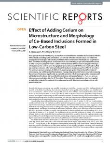
Interfacial intermetallic growth The main intermetallic at the solder/PWB pad interface for all the plating systems, except ENIG, was Cu6Sn5. The appearance of the Cu3Sn layer varies, but it will appear and grow in each case with aging and occupy a greater portion of the intermetallic thickness (See Fig. 2b). While the intermetallic composition was similar, the intermetallic growth rate was different for the different plating systems and for the same type of plating from different manufacturers. The growth was diffusion controlled and, therefore, selflimiting, so that after aging for 1000 hours at 0.9Tm, the differences between the thicknesses of Cu-Sn intermetallics was lessened for all the plating systems, except ENIG, from both manufacturers (Fig. 1).
solder Cu6Sn5 Cu pad
10µm
solder Cu6Sn5
Cu3Sn
void
Cu
Ave. Interm etallic thickness after 1000 hours 0.9Tm aging
Ave. Thickness(m m )
10µm
Cu6Sn5
15 M
10
T
5 0 OSP
Im Sn
Im Ag
HASL
Fig 1. Plot of Average intermetallic thickness after 1000 hours aging at 0.9Tm on Cu based plating systems from “T” and “M” OSP The initial morphology of the intermetallic for both OSPT and OSPM is scallop-like (Fig.2a), but it becomes thicker and more uniform after aging (Fig.2b).It is similar to the intermetallic growth previously observed on bare copper[3]. The growth
Fig. 2 Optical microscopy image of Sn3.8Ag0.7Cu solder joint (without etching) on OSP plating boards. Above: just after reflow; Below: after 1000hours aging at 0.9Tm(168°C)
T 0.8Tm
12
T 0.85Tm
10
M 0.8Tm
6
M 0.85Tm
4
M 0.9Tm
0 0
10
20
30
t1/2(hr1/2)
0
Ave. Thickness(µ m)
T 0.9Tm
8
2
ln(D)( m /hr 1/2)
assuming a more uniform layered shape that was maintained throughout the reflow and subsequent aging. 14 12
-3
OSPT: E=0.58 eV R2 = 0.9982
-4
-7 0.0022
0.8Tm 0.85Tm
0.8Tm
10
0.0023
0.0024 1/T(1/k)
0.0025
0.0026
Fig 3 (a). Plot of Average intermetallic thickness as a function of 1/time for OSPT and OSPM (b). Arrhenius plot for the formation of intermetallic on OSPT and OSPM The activation energy calculated for OSPT (E=0.58eV) is smaller than the activation energy calculated for OSPM (E=0.93eV). This difference results from a poor fit to the growth rate for OSPM (R2=0.85) relative to OSPT (R2=0.9982), resulting from the self-limited growth of the layer with time at the highest temperature. The activation energy calculated for OSPT is calculated from a line with a better correlation coefficient and is therefore a better estimate of the true activation energy. ImSn The intermetallic growth for ImSn is quite different between manufacturers. The intermetallic on ImSnT is scallop-like after soldering and becomes thicker and more uniform after aging. The growth is similar to OSPT and can be modeled using an Arrhenius relationship (Fig. 4). The activation energy for ImSnT is 0.61eV, which is near that of OSPT. But the interfacial intermetallic layer on ImSnM was smooth and uniform in thickness after reflow. This layered structure remained after 1000 hours aging at 0.85Tm with a relatively constant average intermetallic thickness of around 4~5µm. The different growth for ImSnT and ImSnM is probably due to the different plating processes of the different manufacturers. It is believed that in the case of ImSnM that some of the intermetallic was formed before the initial reflow thereby
20 1/2
30
40
1/2
t (hr )
M
OSPM: E =0.93 eV R2 = 0.85
0.9Tm
2 0
T
-2
-6
0.85Tm
0
-1
-5
0.9Tm
10 8 6 4
0
ln(D)(µ m/hr1/2)
Ave. Thickness( m)
14
-1 E=0.61eV R2 = 0.9408
-2 -3 -4 -5 -6 0.0022
0.0023
0.0024
0.0025
0.0026
1/T(1/k)
Fig 4 (a). Plot of Average intermetallic thickness as a function of 1/time for ImSnT (b). Arrhenius plot for the formation of intermetallic for ImSnT ImAg The composition of the interfacial intermetallics on ImAg is the same as those on OSP and ImSn. But intermetallic growth on both ImAgT and ImAgM is irregular and does not follow an Arrhenius relationship, which may be due to changes in the intermetallic thickness as Ag moves from the intermetallic layer and into the bulk solder. As aging continues, intermetallics sometimes increase and sometimes decrease. The average thickness is normally between 3µm and 8µm, but it can reach as high as 12µm or as low as 3.4µm. HASL Cu6Sn5 is the main intermetallic formed at the interface and Cu3Sn appears after longer aging times, as with other plating systems. The growth on HASLT also does not follow an Arrhenius relationship. This is due to Pb/Sn segregation and migration during aging, which leaves behind voids. Intermetallic thickness generally increases with longer aging time and/or higher tempertature. The initial thickness is around 3~5µm and it could reach as high as 12µm after 1000 hours aging at 0.9Tm.
ENIG For ENIG plating, nickel from the pad, together with tin and copper from the solder participate in the reaction to form a ternary intermetallic (Cu,Ni)6Sn5 at the interface. Generally, as aging continues, the intermetallic will grow to a maximum thickness of about 5~6µm due to limited diffusivity of copper through the nickel plating layer, which limits the amount of copper available to form additional intermetallic at the interface and in the bulk.
Intermetallic
10µm
Fig 5. Microstructure of Sn3.8Ag0.7Cu on ENIGT after 10 hours aging at 0.9Tm SnAgCu (CuNi)6Sn5
10µm Ni plating
Cu pad
Fig 6. Intermetallic growth of Sn3.8Ag0.7Cu on ENIGT after 1000 hours aging at 0.85Tm Bulk Microstructure As shown in figure 7, the bulk Sn3.8Ag0.7Cu solder microstructure as reflowed is composed of large Cu6Sn5 intermetallic particles (light area) in a dispersed eutectic phase (dark area), which consists of small Ag3Sn and Cu6Sn5 particles in a tin matrix.
Eutectic phase Cu6Sn5 Sn dendrites
Fig. 7. The microstructure of Sn3.8Ag0.7Cu solder joint on OSP with etching. The characteristics of the intermetallic formation in the bulk solder are similar for the same type of plating from both manufacturers. Large Cu6Sn5 intermetallic appears in the bulk solder after reflow and for all aging conditions for OSP, ImAg, ImSn and HASL plating systems (Fig.1), but rarely happens with ENIG plating. The fact that large Cu6Sn5 intermetallics could not be found in the bulk solder on ENIG plating leads to the conclusion that the nickel plating constrains the underlying copper from dissolving into the bulk solder during reflow and aging. Instead, copper from the solder will have the tendency to migrate toward the interface and contribute to the formation of (CuNi)6Sn5. Undoubtedly, limited availability of copper from the solder has important influence on the growth of (CuNi)6Sn5 and it is the reason the thickness of the intermetallic after aging for 1000 hours is relatively constant for different aging temperature. For the other platings, copper from the pad dissolves into the solder and forms the largest source of Cu for forming large intermetallic Cu6Sn5 with tin in the bulk solder, while the Ag3Sn formed by the Ag in the solder remains small and well distributed in the bulk solder. Shear test After reflow and aging, the solder joints were shear tested. Most of the solder joints failed through the bulk solder. This type of failure is not related to the thickness or composition of the interfacial intermetallic. In addition, the shear strength remained relatively constant during aging for all plating systems, indicating little influence of the bulk intermetallics as well. Both the mean and the distribution remained relatively constant as a function of time, temperature and plating system.
But some interfacial failures were observed after 100 hours aging at 0.9Tm and 1000 hours aging at 0.85Tm for HASL plating systems (Fig 8). A weakened interface was seen above the intermetallic, potentially due to tin from the plating migrating toward the pad and forming intermetallic with copper. This leaves the lead and voids behind and a relatively Pb-rich region will form above the intermetallic. Similar failure has been investigated by Seelig[3] when a product is assembled with Sn/Ag/Cu solder alloy and a Sn/Pb–coated leaded component. Sn/Pb coating will cause lead contamination and result in an intergranular separation due to the formation of a ternary alloy of Sn/Ag/Cu. Further investigation of this phenomenon is ongoing. Loader 10µm Intermetallic
Fig 8 Cross-section of shear failure near intermetallic for SnAgCu on HASLT for aging 100hours at 0.9Tm Conclusions The growth of bulk and interfacial intermetallics between various plating systems and Sn3.8Ag0.7Cu solder is strongly plating dependent, although the composition of the intermetallic is similar (Cu6Sn5 with some Cu3Sn) for all platings except ENIG. Even for the same type of plating from different manufacturers, different intermetallic growth behavior was observed and activation energies calculated for OSPT, ImSnT and OSPM. For the other platings, other factors governing growth made it not possible to fit the growth rate to a simple Arrhenius reliationship. Intermetallic on ImSnM is very steady until 1000 hours aging at 0.85Tm, possibly due to some formation of intermetallic before reflow. Growth on HASLT ImAgT and ImAgM are irregular, due to segregation and diffusion of some of the elements. Availability of copper from the solder is critical in the formation of (CuNi)6Sn5 at the interface on ENIG plating. The only plating which showed a significant weakening at the solder interface after aging was HASL.
References 1. 2.
3.
K.N.Tu et al “Kinetics of interfacial reaction in bimetallic Cu-Sn system”, Acta Metall., 30(1982), pp947-952 S.Choi et al, “Effect of soldering and aging time on interfacial microstructure and growth of intermetallic compounds between Sn-3.5Ag solder alloy and Cu substrates”, J. Electro. Mater., 28(11), 1999,pp1209-1215 K. Seelig, D. Suraski, “Advanced Issues in Assembly: Part 1 Lead Contamination in Lead-free Assembly” SMT 2001