Journal of Computer and Communications, 2014, 2, 78-86 Published Online July 2014 in SciRes. http://www.scirp.org/journal/jcc http://dx.doi.org/10.4236/jcc.2014.29011
Efficient Compressive Multi-Focus Image Fusion Chao Yang, Bin Yang* College of Electric Engineering, University of South China, Hengyang, China * Email:
[email protected],
[email protected] Received April 2014
Abstract Two key points of pixel-level multi-focus image fusion are the clarity measure and the pixel coefficients fusion rule. Along with different improvements on these two points, various fusion schemes have been proposed in literatures. However, the traditional clarity measures are not designed for compressive imaging measurements which are maps of source sense with random or likely random measurements matrix. This paper presents a novel efficient multi-focus image fusion framework for compressive imaging sensor network. Here the clarity measure of the raw compressive measurements is not obtained from the random sampling data itself but from the selected Hadamard coefficients which can also be acquired from compressive imaging system efficiently. Then, the compressive measurements with different images are fused by selecting fusion rule. Finally, the block-based CS which coupled with iterative projection-based reconstruction is used to recover the fused image. Experimental results on common used testing data demonstrate the effectiveness of the proposed method.
Keywords Clarity Measures, Compressive Imaging, Multi-Focus Image Fusion
1. Introduction Multi-focus image fusion, which is a major branch of multi-sensor data fusion, is aimed to produce an all-infocused image from a sequence images with focus on different parts. The multi-focus image fusion can be performed in the transform domain or the spatial domain. In the transform domain, image fusion algorithms are fully implemented via a certain transform technique. In Refs [1] wavelet transform and curvelet transform are applied to image fusion. Refs [2] also exploited a multi-focus image fusion method based on Laplacian pyramid. Moreover, the nonsubsampled contourlet transform (NSCT) is presented in Refs [3]. In spatial domain, fusion rules are directly applied to image pixels or image regions [4]. The simplest fusion method in spatial domain is to take the average of the source images pixel by pixel [5] [6]. A multi-focus image fusion technique proposed by Li et al. [7] is that input images are divided into blocks and better focused ones are selected to compose a resultant image by majority filtering of the source image. Refs [8] proposed an algorithm that focused blocks can *
Corresponding author.
How to cite this paper: Yang, C. and Yang, B. (2014) Efficient Compressive Multi-Focus Image Fusion. Journal of Computer and Communications, 2, 78-86. http://dx.doi.org/10.4236/jcc.2014.29011
C. Yang, B. Yang
be detected via measuring blurriness. In Refs [9], focus measurements are obtained by sum of gradient values of all pixels in each block. Refs [10] presented a simple method using a morphology-based focus measure in a quad-tree structure. The schemes using divided blocks can make calculation simple and fast. In recent years, the compressive sensing theory (CS) presented by D. L. Donoho, E. Candès, and T. Tao has attracted many attentions [11] [12], and [13]. Based on CS, various compressing imaging (CI) systems have been presented. Single-pixel camera architecture [14] implements random linear measurement process of the scene under view that combines sampling and compression. Wan et al. firstly introduced a CS-based image-fusion algorithm which uses “double-star” sampling pattern in a 2-D Fourier domain and shows the recovery via a total variation optimization [15]. However, the partial Fourier matrix is only incoherent with signals that are sparse in the time domain, restricting its practical applications. Ref [16] presented an image fusion scheme under SBHE fast CI that fuses the measurements through a linearly weighted average according to the entropy of measurements. However, as long as the entropies of the measurements did not carry enough information, it could not construct a good reconstructed image. Luo et al. revealed a method that directly performed fusion on the measurement vectors from multiple CI sensors according to the similarity classifications [17]. However, data similarity of measurement vectors needs to analyze much information before fusing. In traditional multi-focus image fusion, pixel clarities are calculated with neighboring pixels or regions. However, the traditional clarities calculations cannot be directly used for the compressive measurements since the random projections contain no geometry structure of source images. In order to solve this problem, a novel multi-focus image fusion method in CS domain is presented in this paper. In the new fusion scheme, the clarity measures bases are trained from natural multi-focus samples. Then, the clarity measures of the raw compressive measurements are not obtained from the random sampling data itself but from the coefficients of Hadamard clarity measure bases trained which can also be obtained from compressive imaging system efficiently. The clarity measures calculated from measurement values are used to guide the fusion rule to get fused image measurements. Finally, the full resolution fused image is constructed from the fused CS sampling measurements. In experimental simulations, the proposed method can get an attractive performance that usually exceeds the quality of other current methods. The rest of this paper is organized as follows: the background of CS and CI are described in Section 2. In Section 3, the proposed method is introduced explicitly. The experiments and analysis are demonstrated in Section 4 .The paper is concluded in Section 5.
2. Compressive Sensing and Compressive Imaging The theory of compressive sensing becomes very popular due to its wide areas of applications. As states in CS theory, the signals can be well recovered from the few measurements by nonlinear optimization if the signal is sparse or compressible. When a n-pixels image is arrangement as a compressible vector x ∈ R n , it can be represented as
x = Ψθ ,
(1)
where Ψ indicates a certain basis and θ is a sparse vector containing only k nonzero coefficients. A random matrix Φ ∈ R k ×n projects the images from high-dimensional space x ∈ R n to a lower-dimensional space y ∈ R k as
y = Φx ,
(2)
where k n . As proved in [18], the random matrix Φ ∈ R k ×n provides a stable embedding that preserves the distance between all pairs of original signals with high probability. According to CS theory, the recovery of signal x from measurement vector y is possible. Imaging techniques have a strong affinity with compressive sensing. Based on CS theory, various hardware implementations of compressive imaging system have been proposed. Single-pixel camera directly acquires random projections of a scene without initial collecting the pixels. The camera architecture employs a digital micro mirror array to optically calculate linear projections of the scene onto pseudorandom binary patterns. CI measurements are the projections of a continuous scene onto a discrete space instead of collecting the lighting intensity at distinct locations [19]. Each measurement is a linear combination of several pixels. Comparing with conventional imaging system, compressive imaging system requires less computation and storage because of compressing during sensing. Due to above some advantages of CI, the compressive imaging system is very fit
79
C. Yang, B. Yang
for applications in visual sensor network.
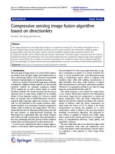
3. The Proposed Method Figure 1 presents the fusion strategy for compressive imaging in visual sensor network. A common scene is observed by two node cameras with different optic setting. Compressive sensing encoding schemes within each sensor directly and independently sample the scene into a small number of randomized measurements denoted by y1 and y2 . Then the measurements y1 and y2 are fused according to certain fusion rule. Finally, the resultant fused image is reconstructed from the combined compressive measurements yF . The key point of this fusion scheme is the focus-level evaluating for random measurements according to which y1 or y2 is focused. Clearly, the focus-level cannot be directly calculated by random sampling coefficients since the random projections don’t contain geometry structure of the source scene. In this work, the innovative point is to design or train image clarity measures bases to evaluate focus-level for compressive imaging system. Firstly, the absolute or norm-1 of the projection measurements with image clarity measures bases can be used as focus-level evaluating. Secondly, the projection measurements can be obtained directly from the compressive imaging system. Thirdly, there is no complex calculation for node cameras. So these characteristics are very suitable for visual sensor network application.
3.1. Clarity Measures Bases Recently, to more effectively fuse the focused regions from multi-focus images, various fusion methods are proposed based on the clarity measures. This paper puts forward a novel image fusion scheme on clarity measures. In this work, we choose 14 pairs of multi-focus images. A fraction collection of the 14 pairs of multi-focus images are presented in Figure 2(a) where the up row gives the clear images and the bottom row gives the blurred images. The two training data sets are randomly taken from a database of 14 natural pairs of multi-focus images. Each set consists of 3584 16 × 16 patches and the Hadamard coefficients of those patches are represented as A and B, respectively. So each column of A and B denotes the Hadamard coefficient of each patch, respectively. Then the coefficient aij , the value of the ith row and jth column of A, corresponds to a Hadamard base which is meaningful to detect and emphasize image salient features. In this work, the aim is to find clarity measures bases from Hadamard matrix and use them to evaluate image focus-level. we suppose each row of coefficient matrix A and B as vector M and vector N, respectively and the length of vector M is same as vector N’s. So xi is the expression value of the sample i in the M and yi is the value of the sample j in the N. s represents the clarity measures. We employ feature selection using Wilcoxon rank sum test [20] that is following y11 ﹦ 〈
﹐
〉 〉
y1Μ﹦ 〈
﹐
〉
…
…
y12 〈 ﹦
﹐
y1F yF2
Φm
CS reconstruct
y12 ﹦ 〈
﹐
〉
y22 ﹦ 〈
﹐
〉
yFΜ
…
Φ2
…
}
… Φ1
…
{
Source image
Fused image
Cameras With different optic setting Μ 2
y 〈 ﹦ Figure 1. The fusion strategy for compressive imaging.
80
﹐
〉
C. Yang, B. Yang
(a) (b)
Figure 2. The training data and the selected bases. (a) Fourteen pairs of multi-focus images; (b) Fifteen selected Hadamard bases.
= S
∑ ∑ P ( ( xi − y j ) ≤ 0 ) ,
(3)
i∈Μ j∈Ν
where P is the logic judge function, if the logic expression in the bracket is true, the value of P is 1,or else it is 0. When s is closer to zero or closer to the value of m × n ( m = M , n = N ), the corresponding row of coefficient matrix is more important to the feature classification. The importance degree of each row of coefficient matrix be calculated. = w max ( ( s, mn − s ) ) .
(4)
According to w of each row of coefficient matrix, the row of coefficient matrix can be ranked. The bigger the value of w is, the more Hadamard basis contributes. So the Hadamard bases are selected from Hadamard matrix responding to the top k rows of coefficient matrix. Figure 2(b) presents fifteen Hadamard bases derived from above method.
3.2. Fusion Scheme Given two multi-focus images I k , k = { A, B} with size of m × n, they are transformed into vectors
{X } i k
mn N k ={ A, B}
using CI hardware. The pixel values in the source blocks can present clear structural information of source image. However, by applying a randomize measurement matrix, the obtained measurements do not preserve the structural information of source blocks any more. In compressive imaging fusion, the focus-level evaluating cannot be obtained by calculating randomized sampling coefficients. Furthermore, it is a key for multi-focus images to evaluate focus-level. In the above section, clarity measures bases are obtained by proposed method, which are integrated a clarity measures matrix Φ′ ∈ R P× N (P the number of Hadamard bases) for compressive imaging system. Then, measurement vectors H 1A , H A2 , , H Ai and H B1 , H B2 , , H Bi can be produced by H ki =Φ′xki , k = { A, B} . In addition, Hi can preserve the structural information of source images and have correlation between each image block comparing with randomize measurements. It is observed that the measurements vectors Hi are greatly sensitive to sampling rate and block size varies. So the focus-level evaluating exist some difference under various conditions. The coefficients ci are absolute value sum of measurements Hi respectively, which characterize evaluating focus-level. In theory, compared with signal-by-signal recovery, joint recovery should provide reliable reconstruction quality from a given collect of measurement vectors, which is equivalent to reduce the measurement burden needed to get better reconstructed quality. The sampling coefficients y A and yB obtained by CS are fused using the maximum rule. i y y1i = iA yB
if ciA ≥ cBi Otherwise
yi y2i = Bi yA i y= F
if cBi ≥ ciA Otherwise
(y
i 1
81
+ y2i
)
2,
,
(5)
,
(6) (7)
C. Yang, B. Yang
where ciA and cBi are the ith coefficients of corresponding X Ai and X Bi , respectively. The yF , the average of measurement vector y1 and y2 , also includes enough information to reconstruct resultant fused image I F . Furthermore, it is very important to use the median filter in fusion scheme, which can make fused images smooth and reduce blocking artifacts. Combined with all the vectors, the fused image I F is reconstructed via a single stage of SPL iterations. In [21], SPL used hard threshold with wiener filter. Using directional transforms can preserve interesting features of traditional transforms in [18].
3.3. Experimental Results and Analysis In order to evaluate performance of the proposed fusion scheme, two sets of multi-focus source images which contain two natural multi-focus image pairs and ten artificial multi-focus image pairs are used to perform the experiments. The natural multi-focus image pairs contain the common used Clock and Lab images with size of 256 × 256 and 256 × 384, respectively. In addition ten standard images are used as ground truth. For each image, two blurred artificial images are created by Gaussian blurring at the left part and right part respectively. Then, the blurred images with different focus points are taken as the source images. In this work, we select two objective evaluation metrics Q AB / F [22] and QW [23] which have been proved to be validated in large degree to perform the quantitative performance evaluation. To reflect a better fusion result, the values of metrics should be as close to 1 as possible. To demonstrate the performance of the proposed method, some well-known multi-resolution based methods including the discrete wavelet (DWT) and gradient pyramid as well as Luo’s method are used to compare with the proposed method. For DWT method, at first, the source images are reconstructed by using sensing coefficients. Then the reconstructed images are fused using based on wavelet method and a final image is gotten. In the gradient pyramid method, first of all, source multi-focus images are reconstructed via using sensing coefficients. Then under these conditions including decomposition levels 2, highpass component adopted absolute maximum and approximate images taken averaging method, the final fused images is obtained by applying an inverse transformation. In method of Luo et al., block Walsh-Hadamard transform matrix is chosen as measurement matrix. Here, the dual-tree discrete wavelet transform (DDWT) [24] is selected as reconstructed method. Contrasting to traditional DWT and discrete cosine transform (DCT), the DDWT has a better preference with shift invariance and significant directional selectivity. Without loss of universality, we provide results at three sampling rates 0.3, 0.5, and 0.7, respectively. Corresponding to each sampling rates, three kinds of block sizes 8, 16, and 32 are individually elected. Then, for all the tested sampling rates and block sizes, the measurements of Clock and Lab would be changed, which is resulted form the increased details of images. The objective evaluation results of two experiments are shown in Table 1, Table 2, respectively. The results in Table 1 and Table 2 indicate that the proposed method achieves superior fusion results comparing with other methods. Though the measurements with absolute maximum cannot directly present salient features of images, it can preserve the contrast information of the source images. Figure 3 presents fusion examples about Clock source images with different focuses. The fused images Figure 3(a), Figure 3(b) and Figure 3(e) have different subjective visual qualities. When sampling rate is set to 0.3 or 0.5, some blocking artifacts are observed on both large and small clock, but the resultant images display better visual effect with sampling rate 0.7. Supposing that sampling rate 0.7 is constant, the quality of fused images are changed along with block-size varies. The analysis from fused results indicates that Figure 3(c) and Figure 3(d) both emerge several significant breakages, while the resultant images display better performance with block-size 16 than other results. In Clock experiment, the maximum values of Q AB / F and QW are corresponding to block-size16, but corresponding to block-size 8 in Lab experiment. However, combining with subjective visual sense, the resultant fused images display better performance at block-size16, because fused images become clearer and the values of Q AB / F and QW also become larger at the same time along with increasing sampling rates. Even though the fused images of the proposed method become smoother, it also improves the quality of the fused images. The fused results of the DWT are obtained using the same reconstructed algorithm, which introduced some artifacts from edges. Figure 4 shows the fused images of Lab which are fused by the proposed method, gradient pyramid, DWT and method of Luo et al. with sampling rate 0.7 and block-size 16, respectively. When two multi-focus images are individually reconstructed via method of CS, two preferable images are obtained. Then a resultant image is fused using above two images by the different methods, such as gradient pyramid or DWT. Each original
82
Table 1. Quantitative assessments of various fusion methods for clock images. Four methods: ours, gradient pyramid, DWT and Luo’s [17] S
QW
Q AB/ F
8
0.818 0.791 0.569 0.357
0.709 0.697 0.575 0.289
16
0.824 0.773 0.535 0.377
0.705 0.687 0.557 0.301
32
0.812 0.774 0.546 0.404
0.690 0.683 0.553 0.319
r
0.3
0.5
0.7
8
0.820 0.773 0.539 0.476
0.713 0.698 0.552 0.391
16
0.832 0.766 0.531 0.511
0.715 0.693 0.553 0.425
32
0.815 0.769 0.533 0.546
0.700 0.689 0.547 0.450
8
0.825 0.769 0.529 0.555
0.723 0.703 0.549 0.477
16
0.8350.768 0.523 0.585
0.722 0.698 0.542 0.515
32
0.816 0.769 0.525 0.620
0.709 0.695 0.539 0.536
0.822 0.772 0.537 0.492
0.709 0.693 0.549 0.411
average
Table 2. Quantitative assessments of various fusion methods for lab images. Four methods: ours, gradient pyramid, DWT and Luo’s [17]
Q AB/ F
QW
r
S 8
0.889 0.847 0.597 0.470
0.688 0.661 0.504 0.241
0.3
16
0.885 0.844 0.569 0.504
0.674 0.654 0.492 0.266
32
0.862 0.834 0.575 0.526
0.661 0.649 0.486 0.291
8
0.891 0.835 0.570 0.588
0.688 0.658 0.483 0.347
16
0.888 0.831 0.557 0.616
0.682 0.655 0.483 0.383
32
0.867 0.829 0.551 0.642
0.671 0.651 0.477 0.411
8
0.893 0.830 0.545 0.652
0.695 0.661 0.475 0.435
16
0.889 0.828 0.544 0.685
0.694 0.657 0.476 0.477
32
0.870 0.827 0.538 0.695
0.680 0.656 0.475 0.490
0.882 0.834 0.560 0.598
0.681 0.656 0.483 0.371
0.5
0.7
average
(a)
(b)
(c)
(d)
(e)
(f)
(g)
(h)
Figure 3. Fusion result of Clock: (a) and (b) Sampling rate 0.3, 0.5 with block-size 16; (c) (d) Block-size 8, 32 with sampling rate 0.7; (e)-(h) Four methods with sampling rate 0.7 and blocksize 16.
83
C. Yang, B. Yang
C. Yang, B. Yang
image is reconstructed by using sensing coefficients, which maybe change its feature, but sometimes also produce explicit results. For the same sampling rate and block-size, the quality of fused images via gradient pyramid-based after reconstructed is superior to those of DWT. Comparing to the other methods, the values of two metrics of the proposed method is larger than that. We can see that the fused image obtained by other methods cannot get more salient feature from two source images. It is observed that the resulting fused images of DWT contain some artifacts form blocking and loss more complementary information. Besides, the proposed scheme achieves better performance and has superiority to the method of Luo et al. to some extent. Furthermore, it takes us short time to fuse source images by compressive sensing. So it can greatly improve efficiency in program run. In addition to classical multi-focus images, some natural images blurred by Gaussian filter are formatted artificial multi-focus images. The proposed method is applied to these images with sampling rate 0.7 as well as block-size 16. Figure 5 shows ten standard images with same size of 256 × 256. Table 3 lists the quantitative results by using two quality measures, which demonstrate that the proposed approach is superior to other methods and confirm successfully that the proposed approach has lots of advantages in fusing the artificial multifocus images.
4. Conclusion In this work, we present a novel image fusion scheme about efficient compressive multi-focus image fusion. The fusion rule is guided by clarity measures and fused image is reconstructed based on blocked CS. The experiments demonstrate that the proposed method provides superior fused images in terms of subjective visual sense as well as objective estimated index. Not only can this method present very clear fused result, but also accelerate the time of multi-focus image fusion. Because of compressing during sensing, fusing less data and reconstructing only one image, we usually spent about 30 seconds in fusing a pair of multi-focus source images on PC. So it greatly improves the efficiency of processing for multi-focus images fusion.
(a)
(b)
(c)
(d)
Figure 4. Fusion result of Lab: (a) The proposed method; (b) Gradient pyramid; (c) DWT; (d) Method of Luo et al.
Figure 5. Ten standard images.
84
Table 3. Quantitative assessments of various fusion methods for artificial multi-focus images.
C. Yang, B. Yang
Four methods: ours, gradient pyramid, DWT and Luo’s [17] Images
QW
Q AB/ F
1
0.873 0.840 0.624 0.737
0.889 0.724 0.708 0.583
2
0.905 0.870 0.696 0.754
0.912 0.712 0.696 0.551
3
0.897 0.870 0.658 0.736
0.913 0.711 0.700 0.513
4
0.899 0.866 0.677 0.777
0.908 0.721 0.710 0.570
5
0.872 0.845 0.489 0.645
0.897 0.688 0.689 0.458
6
0.888 0.864 0.495 0.625
0.906 0.677 0.674 0.416
7
0.875 0.831 0.551 0.723
0.889 0.699 0.690 0.520
8
0.886 0.870 0.534 0.659
0.911 0.673 0.675 0.421
9
0.910 0.878 0.722 0.782
0.913 0.761 0.749 0.663
10
0.9075 0.878 0.631 0.748
0.918 0.676 0.664 0.440
average
0.891 0.861 0.608 0.719
0.906 0.704 0.695 0.513
Acknowledgements This paper is supported by the National Natural Science Foundation of China (Nos. 61102108, 11247214 and 61172161), Scientific Research Fund of Hunan Provincial Education Department (Nos. 11C1101 and 12A115), and the construct program of key disciplines in USC (No.NHXK04).
References [1]
Li, S.T. and Yang, B. (2008) Multi-Focus Image Fusion by Combining Curvelet and Wavelet Transform. Pattern Recognition Letters, 29, 1295-1301. http://dx.doi.org/10.1016/j.patrec.2008.02.002
[2]
Wang, W.C. (2011) A Multi-Focus Image Fusion Method Based on Laplacian Pyramid. Journal of Computational Chemistry, 6, 2559-2566. http://dx.doi.org/10.4304/jcp.6.12.2559-2566
[3]
Zhang, Q. and Guo, B.L. (2009) Multi-Focus Image Fusion Using the Nonsubsampled Contourlet Transform. Signal Process, 89, 1334-1346. http://dx.doi.org/10.1016/j.sigpro.2009.01.012
[4]
Piella, G. (2003) A General Framework for Multi-Resolution Image Fusion: From Pixels to Regions. Information Fusion, 4, 259-280.
[5]
Smith, M.I. and Heather, J.P. (2005) A Review of Image Fusion Technology, Defense and Security. International Society for Optics and Photonics, 29-45.
[6]
Toet, A. (1989) Image Fusion by a Ratio of Lowpass Pyramid. Pattern Pattern Recognition Letters, 9, 245-253.
[7]
Li, S.T., Kwok, J.T. and Wang, Y.N. (2001) Combination of Images with Diverse Focuses Using the Spatial Frequency. Information Fusion, 2, 169-176. http://dx.doi.org/10.1016/S1566-2535(01)00038-0
[8]
Zhang, Y. and Ge, L. (2009) Efficient Fusion Scheme for Multi-Focus Images by Using Blurring Measure. Digital Signal Processing, 19, 186-193. http://dx.doi.org/10.1016/j.dsp.2008.11.002
[9]
Petrovic, V.S., Xydeas, C.S. (2004) Gradient-Based Multiresolution Image Fusion. IEEE Transactions on Image Processing, 13, 228-237. http://dx.doi.org/10.1109/TIP.2004.823821
[10] De, I. and Chanda, B. (2013) Multi-Focus Image Fusion Using a Morphology-Based Focus Measure in a Quad-Tree Structure. Information Fusion, 14, 136-146. http://dx.doi.org/10.1016/j.inffus.2012.01.007 [11] Donoho, D.L. (2006) Compressed Sensing. IEEE Transactions on Information Theory, 52, 1289-1306. http://dx.doi.org/10.1109/TIT.2006.871582 [12] Candes, E.J. and Wakin, M.B. (2008) An Introduction to Compressive Sampling. IEEE Signal Processing Magazine, 25, 21-30. http://dx.doi.org/10.1109/MSP.2007.914731 [13] Candes, E. and Tao, T. (2006) Near-Optimal Signal Recovery from Random Projections: Universal Encoding Strate-
85
C. Yang, B. Yang
gies? IEEE Transactions on Information Theory, 52, 5406-5425. http://dx.doi.org/10.1109/TIT.2006.885507
[14] Baraniuk, R.G. (2008) Single-Pixel Imaging via Compressive Sampling. IEEE Signal Processing Magazine. [15] Wan, T., Canagarajah, N. and Achim, A. (2008) Compressive Image Fusion, Image Processing. 15th IEEE International Conference, 1308-1311. [16] Gan, L., Do, T.T. and Tran, T.D. (2008) Fast Compressive Imaging Using Scrambled Block Hadamard Ensemble. In: EUSIPCO, Lausanne, Switzerland. [17] Luo, X.Y. and Zhang, J. (2010) Classification-Based Image-Fusion Framework for Compressive Imaging. Journal of Electronic Imaging, 19, Article ID: 033009. http://dx.doi.org/10.1117/1.3478879 [18] Candes, E.J., Romberg, J.K. and Tao, T. (2006) Stable Signal Recovery from Incomplete and Inaccurate Measurements. Communications on Pure and Applied Mathematics, 59, 1207-1223. http://dx.doi.org/10.1002/cpa.20124 [19] Sendur, L. and Selesnick, I.W. (2002) Bivariate Shrinkage Functions for Wavelet-Based Denoising Exploiting Inter Scale Dependency. IEEE Transactions on Signal Processing, 50, 2744-2756. http://dx.doi.org/10.1109/TSP.2002.804091 [20] Liao, C., Li, S. and Luo, Z. (2007) Gene Selection Using Wilcoxon Rank Sum Test and Support Vector Machine for Cancer Classification. Computational Intelligence and Security, Springer, Berlin, Heidelberg, 57-66. [21] Gan, L. (2007) Block Compressed Sensing of Natural Images, Digital Signal Processing. 15th International Conference on Digital Signal Processing, 403-406. [22] Xydeas, C. and Petrovic, V. (2000) Objective Image Fusion Performance Measure. Electronics Letters, 36, 308-309. http://dx.doi.org/10.1049/el:20000267 [23] Piella, G. and Heijmans, H. (2003) A New Quality Metric for Image Fusion. IEEE International Conference on Image Processing, Barcelona, 173-176. [24] Kingsbury, N. (2001) Complex Wavelets for Shift Invariant Analysis and Filtering of Signals. Applied and Computational Harmonic Analysis, 10, 234-253. http://dx.doi.org/10.1006/acha.2000.0343
86