METHODS FOR MEDICAL IMAGING by. Ray Maleh. A dissertation submitted in
partial fulfillment of the requirements for the degree of. Doctor of Philosophy.
EFFICIENT SPARSE APPROXIMATION METHODS FOR MEDICAL IMAGING
by Ray Maleh
A dissertation submitted in partial fulfillment of the requirements for the degree of Doctor of Philosophy (Applied and Interdisciplinary Mathematics) in The University of Michigan 2009
Doctoral Committee: Professor Jeffrey A. Fessler, Co-Chair Associate Professor Anna C. Gilbert, Co-Chair Associate Professor Selim Esedoglu Associate Professor Martin J. Strauss
To my Soulmate Christy
ii
ACKNOWLEDGEMENTS
I would like to thank my adviser Anna Gilbert for constantly keeping me on track, for all her help in writing and editing this dissertation, and for supporting me during the preparation of this work. I would like to thank my external adviser Jeffrey Fessler for all his technical suggestions and honest assessments of the performance of my methods, for providing me with corrections related to this work, and for his prompt attention to bureaucratic matters related to my defense. I would like to thank Martin Strauss and Selim Esedoglu for serving on my committee, for reading this dissertation, and for their insightful discussions. I would like to thank Daehyun Yoon for teaching me just about everything I know about MRI scanners and for help with the chapter pertaining to Parallel Excitation in MRI. I would like to thank everyone else who has ever made suggestions related to my work: This list includes, but is not limited to: Doug Noll, Mark Iwen, Paul Shearer, Remi Gribonval, Albert Hero, Raviv Raich, Peter Smereka, Richard Baraniuk, Justin Romberg, Holger Rauhut, Yin Zhang, and many others. I would like to thank my mother and father for their love and motivation. And last but not least, I would like to thank my Soulmate Christy for all her love and for believing in me.
iii
TABLE OF CONTENTS
DEDICATION . . . . . . . . . . . . . . . . . . . . . . . . . . . . . . . . . . . . . . . . . .
ii
ACKNOWLEDGEMENTS . . . . . . . . . . . . . . . . . . . . . . . . . . . . . . . . . .
iii
LIST OF FIGURES
vi
. . . . . . . . . . . . . . . . . . . . . . . . . . . . . . . . . . . . . .
CHAPTER I. Introduction . . . . . . . . . . . . . . . . . . . . . . . . . . . . . . . . . . . . . . . 1.1 1.2
1.3
1.4
The Big Picture . . . . . . . . . . . . . . . . . . . . . . . . . . . . . . . . . . 1.1.1 Contributions of this Work . . . . . . . . . . . . . . . . . . . . . . . Sparse Approximation and Compressive Sensing Background . . . . . . . . . 1.2.1 Convex Optimization Approaches . . . . . . . . . . . . . . . . . . . 1.2.2 Orthogonal Matching Pursuit . . . . . . . . . . . . . . . . . . . . . 1.2.3 Iterative Thresholding and Compressive Sampling Matching Pursuit 1.2.4 Simultaneous Signal Recovery . . . . . . . . . . . . . . . . . . . . . A Mathematical Description of Medical Imaging Devices . . . . . . . . . . . 1.3.1 Parallel-beam Computer Tomography (CT) . . . . . . . . . . . . . 1.3.2 Magnetic Resonance Imaging (MRI) . . . . . . . . . . . . . . . . . Sparse Gradient Images and Total Variation Minimization Techniques . . . . 1.4.1 Notation and Problem Statement . . . . . . . . . . . . . . . . . . . 1.4.2 Total Variation Minimization . . . . . . . . . . . . . . . . . . . . .
II. Restricted Isometry Conditions For Orthogonal Matching Pursuit . . . . . 2.1 2.2 2.3 2.4
. . . .
. . . .
III. Medical Image Recovery using Gradient Orthogonal Matching Pursuit . .
71
Overview . . . . . . . . . . . . . . . . . . . . . . . . . . . . . . . . Edges From Fourier Measurements . . . . . . . . . . . . . . . . . . Integration of Edge Images . . . . . . . . . . . . . . . . . . . . . . 3.3.1 Naive Integration in the Vertical or Horizontal Direction 3.3.2 Haar Wavelet Post Processing Technique . . . . . . . . . 3.3.3 Cross-sectional Post Processing . . . . . . . . . . . . . . 3.3.4 Least Squares Integration Method . . . . . . . . . . . . Theoretical Performance . . . . . . . . . . . . . . . . . . . . . . . Empirical Performance . . . . . . . . . . . . . . . . . . . . . . . .
. . . .
. . . . . . . . .
. . . .
. . . . . . . . .
. . . .
. . . . . . . . .
. . . .
. . . . . . . . .
. . . .
37 37 43 60 63
3.4 3.5
. . . .
1 8 9 11 16 18 22 25 25 27 30 30 33
. . . .
3.1 3.2 3.3
The Basic Orthogonal Matching Pursuit Algorithm . . . . . Variations of Orthogonal Matching Pursuit . . . . . . . . . . Increasing The Number of Atoms Per Iteration Even Further Empirical Evaluation of Algorithms . . . . . . . . . . . . . .
1
. . . . . . . . .
. . . . . . . . .
71 72 75 75 76 79 81 84 93
IV. Parallel Approximation Theory and MRI Excitation . . . . . . . . . . . . . 102
iv
4.1 4.2 4.3
MRI Parallel Excitation . . . . . . . . . Parallel Sparse Approximation Theory Pursuit . . . . . . . . . . . . . . . . . . Parallel Excitation Experiment . . . . .
. . . . . . . . . . . . . . . . . . . . . 102 and Parallel Orthogonal Matching . . . . . . . . . . . . . . . . . . . . . 106 . . . . . . . . . . . . . . . . . . . . . 126
V. Conclusion and Future Work . . . . . . . . . . . . . . . . . . . . . . . . . . . . . 131
BIBLIOGRAPHY . . . . . . . . . . . . . . . . . . . . . . . . . . . . . . . . . . . . . . . .
v
139
LIST OF FIGURES
Figure 1.1
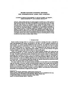
The famous Shepp-Logan Phantom image: a classical example of a sparse gradient image. . . . . . . . . . . . . . . . . . . . . . . . . . . . . . . . . . . . . . . . . . . .
3
1.2
A schematic of the basic compressive sensing problem . . . . . . . . . . . . . . . .
10
1.3
Pseudocode for OMP . . . . . . . . . . . . . . . . . . . . . . . . . . . . . . . . . .
17
1.4
Pseudocode for Iterative Thresholding . . . . . . . . . . . . . . . . . . . . . . . . .
19
1.5
Pseudocode for CoSAMP . . . . . . . . . . . . . . . . . . . . . . . . . . . . . . . .
21
1.6
A schematic of the basic simultaneous compressive sensing problem . . . . . . . . .
23
1.7
Pseudocode for SOMP(p) . . . . . . . . . . . . . . . . . . . . . . . . . . . . . . . .
24
1.8
Basic Parallel-beam CT Setup: x-rays are shot at an angle in order to generate a projection . . . . . . . . . . . . . . . . . . . . . . . . . . . . . . . . . . . . . . . . .
25
Visualization of frequencies over which one can obtain the Fourier Transform of an image via computer tomography. . . . . . . . . . . . . . . . . . . . . . . . . . . . .
27
Using an RF-pulse to introduce a magnetic field orthogonal to B0 results in the precession of M around the z-axis at frequency ω0 = γ|B0 |. . . . . . . . . . . . . .
28
1.11
Algorithmic sketch of Fast Total Variation Deconvolution. . . . . . . . . . . . . . .
35
2.1
Atom selection critera for OMP, KOMP, StOMP, and OMP-thresh. . . . . . .
44
2.2
Graphical illustration of when thresholding is useful. . . . . . . . . . . . . . . . . .
45
2.3
Restricted isometry bounds for 2-OMP with sparsity parameter T = 50. . . . . . .
53
2.4
Advantage of StOMP and 2-OMP over OMP for sparse signal recovery in terms of a restricted isometry condition on δ2 . . . . . . . . . . . . . . . . . . . . . . . . .
56
Advantage of 2-OMP over OMP for general signal recovery in terms of a restricted isometry condition on δ2 . . . . . . . . . . . . . . . . . . . . . . . . . . . . . . . . . .
59
2.6
Pseudocode for Hybrid α-OMP . . . . . . . . . . . . . . . . . . . . . . . . . . . .
61
2.7
Probability of exact reconstruction of T -sparse signals using various compressive sensing algorithms. . . . . . . . . . . . . . . . . . . . . . . . . . . . . . . . . . . . .
64
1.9
1.10
2.5
vi
2.8
Runtimes of various compressive sensing algorithms when recovering T -sparse signals. 65
2.9
Average reconstruction errors in recovering signals with exponentially decaying coefficient generated by the various compressive sensing algorithms as a function of the sparsity parameter T . . . . . . . . . . . . . . . . . . . . . . . . . . . . . . . .
67
Average T -term reconstruction errors in recovering signals with exponentially decaying coefficient generated by the various compressive sensing algorithms as a function of the sparsity parameter T . . . . . . . . . . . . . . . . . . . . . . . . . . .
68
Log-log plot of the average runtimes of compressive sensing algorithms as a function of the signal length. . . . . . . . . . . . . . . . . . . . . . . . . . . . . . . . . . . . .
69
2.12
Power law asymptotical analysis of compressive sensing algorithms. . . . . . . . . .
69
3.1
Outline of the GradientMP algorithm. . . . . . . . . . . . . . . . . . . . . . . . .
72
3.2
Comparison of DiffMP and GradientMP reconstructions of a Shepp-Logan phantom from 6.6% of its Fourier coefficients. . . . . . . . . . . . . . . . . . . . . .
74
Examples of minor and severe streakiness in both the vertical and horizontal directions. . . . . . . . . . . . . . . . . . . . . . . . . . . . . . . . . . . . . . . . . . . . .
77
3.4
Haar Wavelet Transforms of Streaky Images. . . . . . . . . . . . . . . . . . . . . .
78
3.5
Shepp Logan phantom with streakiness corrected by the Haar Wavelet method vs. the original phantom. . . . . . . . . . . . . . . . . . . . . . . . . . . . . . . . . . . .
79
Cross-sections of orginal phantom, vertically streaked phantom, horizontally streaked phantom, and finally the reconstruction of the horizontally streaked image based on the cross-section method. . . . . . . . . . . . . . . . . . . . . . . . . . . . . . . .
80
3.7
Reduction of streakiness using cross-section method. . . . . . . . . . . . . . . . . .
81
3.8
Shepp Logan phantom reconstruction using the least squares integration technique vs. the original phantom. . . . . . . . . . . . . . . . . . . . . . . . . . . . . . . . .
84
3.9
The directions of differences in an 8 × 8 Haar Wavelet expansion. . . . . . . . . . .
86
3.10
Single streak image along with its full Haar Wavelet Transform as well as its Haar Wavelet Transform restricted to vertical and diagonal differences only. . . . . . . .
88
Sets of low frequencies that, when included in Ω, will yield stable edge integration performance guarantees. . . . . . . . . . . . . . . . . . . . . . . . . . . . . . . . . .
92
3.12
Original Shepp-Logan Phantom along with its full and partial Fourier Transforms.
93
3.13
Various reconstruction of the Shepp-Logan phantom from 10% of its Fourier Coefficients. . . . . . . . . . . . . . . . . . . . . . . . . . . . . . . . . . . . . . . . . . .
94
Various reconstruction of the Shepp-Logan phantom from Fourier Coefficients along radial lines. . . . . . . . . . . . . . . . . . . . . . . . . . . . . . . . . . . . . . . . .
96
2.10
2.11
3.3
3.6
3.11
3.14
vii
3.15
3.16
3.17
Reconstruction NRMSEs and Runtimes of GradientMP and TV-Minimization with respect to recovering a 64 × 64 Shepp-Logan phantom. . . . . . . . . . . . . .
97
Reconstruction NRMSEs and Runtimes of GradientMP and TV-Minimization with respect to recovering 64 × 64 Shepp-Logan phantoms corrupted with a significant amount of white Gaussian noise. . . . . . . . . . . . . . . . . . . . . . . . . .
98
Original peppers image and reconstructions using Fourier Back Projection, GradientMP, and FTVd. . . . . . . . . . . . . . . . . . . . . . . . . . . . . . . . . . .
99
3.18
Original medical image and reconstructions using Fourier Back Projection, GradientMP, and FTVd. . . . . . . . . . . . . . . . . . . . . . . . . . . . . . . . . . . 100
4.1
Typical single coil sensitivity pattern . . . . . . . . . . . . . . . . . . . . . . . . . . 103
4.2
Typical sensitivity patterns for an 8-coil MRI machine. . . . . . . . . . . . . . . . . 103
4.3
An idealized in-plane excitation profile that is identically one over the region of interest. . . . . . . . . . . . . . . . . . . . . . . . . . . . . . . . . . . . . . . . . . . 105
4.4
An illustration of a pulse sequence in MRI parallel excitation. . . . . . . . . . . . . 105
4.5
A graphical depiction of the multiple input single output structure of the basic parallel compressed sensing / sparse approximation problem. . . . . . . . . . . . . 107
4.6
Pseudocode for Parallel Orthogonal Matching Pursuit. . . . . . . . . . . . . . . . . 109
4.7
A circular excitation pattern of radius 10.125 cm over a 24 cm by 24 cm viewing area127
4.8
The NRMSEs of the excitation patterns induced by convex optimization and the three variations of POMP in the case of a single coil MRI setup . . . . . . . . . . 128
4.9
The NRMSEs of the excitation patterns induced by convex optimization and the three variations of POMP in the case of an 8-coil MRI setup . . . . . . . . . . . . 129
viii
CHAPTER I
Introduction
1.1
The Big Picture
For thousands of years ever since the days of Hippocrates, doctors had to face the daunting task of diagnosing and treating all sorts of medical ailments without the ability to view the “insides” of their patients. It was not until the last one-hundred twenty years that great advances were made in the field of medical imaging. In the mid 1890’s, x-rays were first used to image two-dimensional projections of bones and other objects within the human body. While this in itself was a remarkable discovery that aided doctors tremendously, these projections did not paint an entire threedimensional picture and training was required to accurately interpret these images. The more modern imaging modalities such as CT scans (computer tomography) and MRI (magnetic resonance imaging) were developed in the 1970’s in order to generate cross-sectional images of slices of the human body. These slices can be assembled together to paint an overall picture of a person, inside and out. These images are generally much more powerful in terms of revealing anatomical structures, such as tumors or arterial blockages, that may otherwise not be visible in a poorly produced x-ray image. Physically speaking, CT and MRI work based on two different principles. CT
1
2
scanners generate images by shooting x-rays through a patient from all angles and interpolating between the resulting projections to obtain a final cross-sectional image. This work will consider only the simple case of parallel-beam CT where the paths of the x-rays are parallel and the projections are formed on “flat screens”. More modernized fan-beam CT systems where x-rays are shot from a motorized source traversing a circle and forming projections onto an arc will not be considered here. On the other hand, MRI works by subjecting a patient’s body to varying (gradient) magnetic fields in order to force protons within the subject to precess magnetically at different frequencies depending on their position. These precessing protons will induce a signal through a receiver coil, which can be interpreted to generate an image. A more thorough discussion regarding the operation of these devices is presented in Section 1.3. While these scientific principles are somewhat different, parallel-beam CT and MRI share one important mathematical property: they both obtain an image by measuring its Fourier spectrum. Since an image is spatially limited, an imaging machine must sample the frequencies in Fourier Space at a rate greater than the Nyquist rate, i.e. the minimum sampling rate that will guarantee no aliasing effects [47]. Now, assuming it is possible to sample at the Nyquist rate, then it is a trivial matter to reconstruct the image by utilizing an Inverse Fast Fourier Transform (IFFT). Unfortunately, obtaining all these samples isn’t always very practical: CT scanners and MRI devices tend to be slow, loud, claustrophobic, and generally uncomfortable for patients. Thus, it behooves the medical community to find ways of obtaining high quality medical images utilizing the fewest Fourier Transform coefficients as possible. Luckily, the images of interest tend to enjoy the property of being sparse in gradient. In other words, they consist of large, nearly constant-valued regions separated by
3
edge-discontinuities. The redundancies in these images suggest a possible dimensionality reduction that should allow for Fourier sampling at sub-Nyquist rates. An example of a sparse-gradient image along with an image of its edges is shown below in Figure 1.1.
Figure 1.1: The famous Shepp-Logan Phantom image: a classical example of a sparse gradient image.
Mathematically speaking, one has some sparse-gradient image X and some subset Ω of all possible frequency pairs. The objective is to reconstruct X with knowledge only of Ω and y := FΩ X
(1.1)
where FΩ is a 2D Fourier Transform operator restricted to the frequencies specified by Ω. When performing this reconstruction, it is important to keep the following three goals in mind: 1. Make the size of Ω as small as possible to minimize the data that must be collected. In MRI, this translates into faster scan times. 2. Convert the raw Fourier data into a final image using a fast, efficient algorithm so that patients do not need to wait long for their results.
4
3. Ensure that the final image is an accurate representation of the original image to avoid misdiagnoses. As a side note, the reason that fan-beam CT is not considered in this work is because a high angular sampling rate is required to adequately interpolate the raw data into parallel-beam coordinates over which a Fourier Transform of the image can be computed. This means that for this particular imaging modality, it is detrimental to reduce the size of Ω. To reach the above objectives, this work will appeal to the theory of sparse approximation, an area mathematics which has enjoyed significant progress during the last decade or so. In this field, there are several results that state that if some signal (or image) is sparse, say in the Euclidean sense, then it can be recovered exactly with exponentially fewer linear (e.g. Fourier) measurements than the dimension of the actual signal. It should be noted that sparse approximation is closely related to the relatively new field of compressive sensing (see [9]). The basic linear problem from both fields can be modeled by the simple-looking equation: (1.2)
y = Φx
where in this particular case (which happens to be a compressive sensing application), x is a sparse signal/image, Φ is a measurement matrix, and y is a set of linear measurements of x. The objective is to recover x with knowledge of only Φ and y. Observe the similarity between this equation and Equation 1.1. For the purposes of this overview, the technical difference between sparse approximation and compressive sensing is not terribly important, and therefore, a discussion of this issue is deferred to Section 1.2 Several algorithms utilizing convex optimization and/or greedy basis selection
5
techniques have been developed mainly for this purpose. Basis Pursuit (BP), discussed in detail by Candes et. al in [5], Donoho in [13], and others, is an example of an optimization principle that, given Fourier observations of a sparse signal, will attempt to seek the sparsest signal (in the `1 sense) that satisfies the imposed Fourier constraints. In general, Basis Pursuit signal reconstructions are of very high quality; however, algorithms that implement Basis Pursuit are typically very slow. As a result, this methodology may not be appropriate for large signals or time-sensitive procedures. Fortunately, there are faster alternatives. A simpler optimization problem would be to find the signal with the least energy that satisfies the Fourier constraints. While this turns out to be mathematically equivalent to an inverse Fourier Transform with all unknown Fourier coefficients set to zero, reconstruction quality is often very poor. However, this procedure, also known as Fourier Back-Projection, is excellent at identifying the few Euclidean basis elements that contribute the most to the representation of the signal. The most simple compressive sensing algorithm of all, Thresholding (see [52]), works entirely based on this principle. Based on previous results in statistical theory, Mallat (see [41] and [42]) introduces an algorithm known as Matching Pursuit (MP) which attempts to use the Fourier data to iteratively identify the few Euclidean basis elements that make up a sparse signal. While every iteration is extremely fast, there is no known bound on the number of iterations required for convergence. To address this problem, one can use a slightly augmented version of the algorithm known as Orthogonal Matching Pursuit (OMP) (see [58] and [61]), which uses an orthogonalization step to ensure that no single basis element gets selected more than once in subsequent iterations. Thus, the number of iterations must be bounded. However, this comes at the expense of a quadratic runtime with respect to the signal sparsity thanks to the least squares procedure that must
6
now be carried out. One can make OMP faster by allowing more than one basis element to be selected at any given iteration. This is the primary motivation of the K-fold Orthogonal Matching Pursuit (KOMP) and Stagewise Orthogonal Matching Pursuit (StOMP) procedures described in [22] and [15] respectively. By selecting more than one item per iteration, one typically reduces the number of total iterations needed for recovery, and therefore, the total number of least squares problems that must be solved. Up until now, these algorithms have not been known to satisfy any sort of performance guarantees based on restricted isometry conditions. In contrast, Basis Pursuit has been shown to possess such properties (e.g. [7] and [6]). A significant contribution of this work is the development of restricted-isometry-property-based sufficient conditions that guarantee the correctness of Orthogonal Matching Pursuit as well as several of its variants. While the restricted isometry conditions pertaining to OMP are not as powerful as its Basis Pursuit counterpart, it will be shown that as one increases the number of elements that may be selected per iteration, one will obtain results that approach the Basis Pursuit golden standard. This analysis will provide some intuition as to why more recently developed algorithms, such as Regularized Orthogonal Matching Pursuit (ROMP), Compressive Sampling Matching Pursuit (CoSAMP), and Iterative Thresholding (IT) (see [46], [45], and [3] respectively), do satisfy these conditions. These three algorithms share the property that they all attempt to simultaneously select all the correct basis elements during every iteration. It is possible to generalize the theory of sparse signal recovery to cover the case of reproducing sparse-gradient images from a small number of Fourier measurements. In works such as [5], [33], and others, convex optimization methods similar to Basis Pursuit are used to recover such images. These methods seeks the image of smallest
7
total variation (TV) that satisfies (or approximates) the given Fourier constraints produced by the imaging device. While such constrained TV-minimization procedures greatly reduce the number of Fourier coefficients that must be sampled and are highly effective at producing high quality results, they are extremely slow. One approach to making them faster would be to relax the setup into an unconstrained optimization problem where deviations from the Fourier constraints are penalized [10, 64]. Such methods are faster; however, their theoretical convergence rates can be slow. This work presents an entirely different approach: It is possible to embed any one of the various orthogonalized matching pursuit algorithms as a black box device within an encompassing algorithm, called Gradient Matching Pursuit (GradientMP), that works specifically to solve the same sparse-gradient image reconstruction problem as shown in (1.1). From a high level point of view, GradientMP has three basic steps. 1. It first modifies the original Fourier measurements to obtain Fourier measurements of the corresponding vertical and horizontal edge images. 2. It then utilizes some algorithm from the suite of matching pursuit routines (e.g. OMP, KOMP, CoSAMP, etc.) to recover the edge images. 3. Finally, it recovers the original image from the estimates of its edges using one of several specialized integration techniques. This procedure will be discussed in much more detail later. The layout of this work is as follows: The remainder of this chapter will be devoted to presenting background material related to sparse approximation and compressive sensing theory as well as a mathematical description of computer tomography and
8
magnetic resonance imaging. This is followed by a detailed discussion of the sparse gradient image approximation problem and a survey of previous work. After this thorough introduction, the main contributions of this work are presented: 1.1.1
Contributions of this Work
Chapter II features a detailed theoretical analysis of orthogonal matching pursuit and its variants. Several performance guarantees based on restricted isometry conditions will be proven for these algorithms. This analysis will theoretically justify the use of OMP-like algorithms for use in applications. In other words, this chapter will explain why orthogonal matching pursuit should not be thought of as a mere heuristic. Chapter III introduces the Gradient Matching Pursuit algorithm and proves performance guarantees pertaining to the various edge integration schemes. These guarantees, combined with the results of Chapter II, establish the theoretical correctness of Gradient Matching Pursuit under certain conditions. However, even in cases where these conditions are not met (such as in natural images), it will be shown that the output of Gradient Matching Pursuit compares well with that of Total Variation Minimization in term of accuracy; however, with respect to runtime, Gradient Matching Pursuit is much faster. Chapter IV takes on a new direction by attempting to solve the MRI excitation problem: In MRIs with non-ideal RF transmission coils, the strength of a transmitted pulse is not uniform over the imaging region of interest. The result of this is unwanted contrast in the final image reconstruction. Regardless of whether an MRI machine consists of a single coil or multiple transmission coils, this lack of homogeneity can be corrected by transmitting a “short” sequence of weighted RF subpulses modulated by specially selected two-dimensional waveforms induced by linear gra-
9
dient magnetic coils (see [69], [27], and [68]). The word “short” provides a hint as to where sparsity arises in this setup. In a single coil MRI, selecting this sequence of subpulses translates into a sparse approximation problem easily solvable by either convex optimization or a greedy algorithm like OMP. The parallel coil case is harder. To address this scenario, this chapter will provide an introduction to parallel sparse approximation and compressive sensing theory, which has appeared in the literature in various mathematically equivalent forms (see [54] and [67]). This is followed by a presentation of this work’s contribution to the world of parallel approximation which is the development of an efficient generalization of Orthogonal Matching Pursuit known as Parallel Orthogonal Matching Pursuit (POMP). POMP is effectively an interpolation between OMP and its relative Simultaneous Orthogonal Matching Pursuit (SOMP) [62]. This chapter proves several compressive sensing and sparse approximation related theoretical results pertaining the performance of POMP and its many variations. Then it will be shown how POMP can be used effectively to solve the MRI Parallel Excitation (i.e. many transmission coils) problem as accurately as conventional convex optimization techniques, but in much less time. After presenting three major contributions to the fields of sparse approximation theory, compressive sensing, and medical imaging, this work will conclude by outlining several related questions that are still open for investigation. 1.2
Sparse Approximation and Compressive Sensing Background
To get an understanding of how compressive sensing can be used to recover medical images from Fourier data, it is important to understand the basics of this field. For the purposes of this chapter, it will be assumed that x ∈ CN is a one-dimensional signal of length N . All results presented here are easily adaptable to the two-
10
dimensional case. The signal (or vector) x is said to be T -sparse if the number of non-zero entries in x is at most T . The matrix Φ ∈ CM ×N denotes a measurement matrix and y = Φx ∈ CM
(1.3)
is a set of M linear measurements of x where M is assumed to be significantly smaller than N . A graphical schematic of this problem is shown in Figure 1.2.
Figure 1.2: A schematic of the basic compressive sensing problem
As a notational convention, let φi , 1 ≤ i ≤ N denote the columns of Φ. Also, given A ⊆ {1, · · · , N }, ΦA denotes the M × |A| sub-matrix of Φ corresponding to the indices in A. The basic compressive sensing problem is to solve for x having knowledge of only y and Φ. This problem is superficially equivalent to the basic linear sparse approximation problem where we are given a signal y ∈ CM , an over-complete dictionary Φ, and the task of trying to represent y as a sparse linear combination of the φi s. In both sparse approximation and compressive sensing, the columns φi are often referred to
11
as “atoms.” To the outsider and occasionally to even the most seasoned mathematician, the difference between compressive sensing and sparse approximation can be confusing and seem somewhat insignificant. After all, they both involve solving the same underdetermined problem Φx = y. In addition, the same algorithms can be used in both situations. So what exactly is the difference and why is it a big deal? In simple terms, the main difference between compressive sensing and sparse approximation is that x is the signal of interest in compressive sensing whereas y is the signal of interest in sparse approximation theory. The important distinction lies in the theoretical analyses of compressive sensing and sparse approximation algorithms. Suppose one has an algorithm A that solves both problems. In compressive sensing, one would like to know if A satisfies a performance guarantee of the form ||x− x˜|| ≤ C||x−xopt || where x is some given signal (not necessarily sparse), x˜ is the T -term approximation of x returned by A, xopt is the optimal T -term representation of x, and || · || is some suitably selected norm. On the other hand, in sparse approximation theory, one wants to know if A will return an approximation y˜ of y satisfying ||y − y˜|| ≤ C||y − yopt ||. The methods of proof for both styles of guarantees as well as the utilized norms can be different. Thus, to a theorist, compressive sensing and sparse approximation are far from being one and the same. One frequently runs into application of both compressive sensing and sparse approximation in medical imaging and therefore this work will consider results pertaining to both situations. 1.2.1
Convex Optimization Approaches
Regardless of whether one is working in the realm of compressive sensing or sparse approximation, solving y = Φx is a highly under-determined problem and several
12
solutions may exist. However, if a sparsity constraint is enforced on x, the problem becomes more interesting. For example, if it is known that x is significantly sparse, one could attempt to solve (1.3) by attempting to find the sparsest signal z ∈ CN that satisfies Φx = Φz. This equates to solving the non-convex optimization problem: (P0)
x˜ = argmin ||z||0
s.t. Φz = Φx.
z
Here, || · ||0 denote the `0 “norm”, which does nothing but count the number of nonzero entries in its argument. Unless P = N P , there is no polynomial-time algorithm that will, in general, solve (P0). As a result, mathematicians typically relax (P0) into the convex optimization problem shown below: (P1)
x˜ = argmin ||z||1
s.t. Φz = Φx.
z
P Now ||·||p for p > 0 denotes the usual `p norm, i.e. ||x||p = ( i |xi |p )1/p for 0 < p < ∞ and ||x||∞ = maxi |xi |. There are several algorithms that can solve (P 1) in runtime polynomial in N . These include simplex methods, interior point methods, and second order cone programs for complex-valued signals and measurements. These algorithms can be collectively thought of as a generalized algorithmic entity known as Basis Pursuit (BP) [11]. The next logical question to consider is for what types of signals x and measurement matrices Φ is it possible solve (1.3) using (P0) or (P1)? To answer this question, it is essential to introduce the notion of a restricted isometry property (RIP) [4]. Definition I.1. It is said that an M ×N measurement matrix Φ satisfies a restricted isometry property if there exists some number δT ∈ [0, 1) such that for every T -sparse signal x, it is the case that (1 − δT )||x||22 ≤ ||Φx||22 ≤ (1 + δT )||x||22 .
13
The number δT is called a restricted isometry number and is a function of the sparsity level T . Based on the kind of restricted isometry property that a certain measurement matrix Φ enjoys, one can determine a sparsity level T such that all T -sparse signals are recoverable by (P0) or (P1). This is illustrated by the following two propositions. Proposition I.2. Suppose one is given a measurement matrix Φ with restricted isometry numbers δ2T < 1. Then the non-convex optimization problem (P0) will recover uniquely any T -sparse signal x given only Φ and Φx. Proof. Suppose not. Assume there are two different T -sparse (or less) signals x1 and x2 such that Φx1 = Φx2 . Let h = x1 − x2 . Then Φh = 0 by linearity. But by the RIP, (1 − δ2T )||h||2 ≤ ||Φh||2 = 0. Since δ2T < 1, it follows that h = 0, which is a contradiction. In regards to (P1), one can also prove: Proposition I.3. Suppose one is given a measurement matrix Φ with restricted isometry numbers satisfying δT + δ2T + δ3T < 1, then the convex problem (P1) will recover uniquely any T -sparse signal x given only Φ and Φx. The proof of the latter proposition is significantly more involved and can be found √ in [8]. Candes et. al [6] improve this result to only require that δ2T < 2 − 1. Of course, most interesting signals are not truly T -sparse, but only T -sparse up to some additive noise. In addition, there may be some additional measurement noise. To that end, suppose that x is any signal and xT is the best T -term representation of x, i.e., the largest T terms of x in magnitude. Furthermore, suppose that the given measurements are noisy and take the form y = Φx + e where e represents the
14
measurement noise. Then one may attempt to recover x by solving the following optimization problem: x˜ = argmin ||z||1
(PN)
s.t. ||Φz − y||2 ≤ ||e||2 ,
z
which yields the mixed-norm recovery guarantee shown in the following result: Proposition I.4. If Φ is a measurement matrix such that the restricted isometry numbers satisfy (1.4)
δ3T + 3δ4T < 2,
then the solution of (PN) satisfies: � (1.5)
k˜ x − xk2 ≤ O (kek2 ) + O
� 1 √ kx − xT k1 . T
The proof of this result can also be found in [6]. In addition, one can show that the T -term truncation x˜T of x˜ satisfies: � (1.6)
k˜ xT − xk2 ≤ O (kx − xT k2 ) + O
1 √ kx − xT k1 T
� + O (kek2 ) .
An important question to the compressive sensing community how to construct measurement matrices that satisfy the restricted isometry property (1.4). Certainly, if Φ is a square matrix with orthonormal vectors, then the RIP is trivially satisfied. Of course, this case is not very interesting. In an attempt to construct useful examples, mathematicians began experimenting with random matrices consisting of appropriately normalized Gaussian measurements (see [8], [7], and [49]). By selecting an M × N matrix Φ with Gaussian measurements where M is large enough, i.e. � (1.7)
M = Ω T log
�
N T
�� ,
15
then Φ will satisfy restricted isometry properties such as (1.4) with high probability. This result was extended to measurement matrices whose entries follow any SubGaussian distribution [44]. A special case of these distributions is the Bernoulli (0 or 1) distribution which arises in digital compressive sensing applications such as the Rice University Single-Pixel Camera project [28]. This work’s primary concern is partial Fourier measurements. In other words, it is of great importance to be able to recover a sparse signal x from a small subset of its Fourier coefficients. To do this, one can define a special measurement matrix ΦF that is generated by selecting M rows of an N × N Discrete Fourier Transform (DFT) matrix uniformly at random. The question is: given a sparsity level T and signal size N , how many Fourier measurements M are needed so that Φ satisfies the restricted isometry property in (1.4). This question was answered in 2008 by Rudelson and Vershynin [50]. They prove the following proposition: Proposition I.5. If M = O(T log(N ) log2 (N ) log(T log(N )), then ΦF will have restricted isometry numbers that satisfy δ3T + 3δ4T < 2 with exponentially high probability. By combining this result with Proposition I.4 and using the fact that T ≤ N , one obtains the following corollary. Corollary I.6. If M = Ω(T log4 (N )), then, with high probability, solving (PN) will yield a solution x˜ that satisfies the condition in Equation 1.5. In particular, if x is precisely T -sparse and there is no measurement noise, then (PN) will reconstruct x from its measurements exactly. The quantity Ω(T log4 (N )) � N for sufficiently large N and small enough T . This
16
means that it is possible to recover a sparse signal x from far fewer Fourier coefficients than the signal size. In many cases, one can recover x from fewer measurements than what would otherwise be dictated by the Nyquist rate. As an additional note, many mathematicians conjecture that one only really needs Ω(T log(N )) Fourier measurements to guarantee the RIP condition shown in Proposition I.4. As an illustration of the benefit one would obtain from proving such a conjecture, assume x is a 10-sparse signal of length 22 0. The established result M = Ω(T log4 (N )) implies that on the order of 1,600,000 Fourier measurements would be required to recover the signal. The conjecture reduces this number to something on the order of 200. 1.2.2
Orthogonal Matching Pursuit
As seen in the previous section, `1 minimization is a tractable method of solving compressive sensing problems. Unfortunately, algorithms that utilize this methodology to solve this problem tend to be extremely slow. To overcome this issue, other “greedy” techniques have been designed to solve the same problems but with more rapid localized iterative schemes. The most classical of these are Matching Pursuit (MP) (see [42]) and its more powerful brother Orthogonal Matching Pursuit (OMP) (see [22] and [60]). A pseudocode listing of the Orthogonal Matching Pursuit algorithm is shown in Figure 1.3: OMP works by taking the measurement vector y and expressing it as a sparse linear combination of the φi s, i.e. the columns of Φ. In every iteration, the algorithm selects the column that most closely resembles the current residual in the representation of y. An orthogonalization step is used to ensure that no column is selected more than once. Ideally, by iterating this procedure T times, it should be possible to express y as the exact linear combination of T columns of Φ which form
17
Algorithm:
Orthogonal Matching Pursuit
Inputs: Φ, y = Φ, Sparsity T Outputs: T term approximation x ˜ to x Initialize r0 = y, Λ = ∅ For t from 1 to T { Set λt = argmax |(Φ∗ rt−1 )i | i
Set Λt = Λt−1 ∪ {λt } Set at = argmin kΦΛt a − yk2 . a
rt = y − ΦΛt at } Set the entries of x ˜ corresponding to indices ΛT equal to aT . other entries equal to zero.
Set all
Pseudocode for OMP
Figure 1.3:
its representation. If y is reconstructed exactly, then x will be recovered exactly as well. Previously derived sufficient conditions that guarantee the correctness of the OMP algorithm utilize some additional machinery different from the restricted isometry property presented earlier. To that end, it is necessary to define an alternate notion of how close the columns of Φ resemble each other. Definition I.7. Given a dictionary Φ with atoms φi , 1 ≤ i ≤ N , the cumulative coherence µ(T ) is defined, as a function of the sparsity parameter T , to be: µ(T ) = max max i
|Λ|=T
X
|φ∗i φj | .
j∈Λ i∈Λ /
The special case µ(1) is simply referred to as the coherence of the dictionary. In [58], Tropp proves a sufficient condition that guarantees that OMP will recover x from Φ and Φx. Proposition I.8. Suppose that Φ is a dictionary and T is a sparsity parameter such
18
that µ(T ) + µ(T − 1) < 1,
(1.8)
Then OM P will correctly recover any T -sparse signal x from its measurements. With respect to sparse approximation, Tropp also proves an `2 -`2 performance guarantee pertaining to OMP’s ability to reconstruct some signal y as a T -linear combination of atoms of Φ. Proposition I.9. Suppose that Φ is a dictionary and T is a sparsity parameter such that µ(T ) < 0.5. Then, OMP will produce a T -term approximation y˜ of some signal y such that s (1.9)
k˜ y − yk2 ≤
1+
T (1 − µ(T )) ky − yT k2 (1 − 2µ(T ))2
where yT is the optimal T -term representation of y in Φ. 1.2.3
Iterative Thresholding and Compressive Sampling Matching Pursuit
While Basis Pursuit is slow, its performance is governed by powerful restricted isometry conditions. On the other hand, OMP works very well in practice, is easily implementable, and runs much faster than convex optimization routines. However, its performance guarantees, including those based on the restricted isometry conditions that will be presented in Chapter II, are not as powerful as its slower counterpart. As a result, one may wonder if there is some happy medium, i.e. an algorithm that is as fast and easily implementable as OMP, but also satisfies RIP-based performance guarantees similar to those of convex optimization. The answer turns out to be yes. The first such algorithm is called Iterative Thresholding (IT) [3]. The main idea behind iterative thresholding is quite simple. Given measurements y = Φx of some T -sparse signal x, then assuming Φ is nearly unitary, then x1 =
19
(Φ∗ y)T = (Φ∗ Φx)T , where (·)T is the non-linear operator that prunes its argument to the top T entries, should be a somewhat good approximation to x. Recall that the restricted isometry property provides a measure of how close a measurement matrix Φ is to being unitary. Now to improve upon this estimate, one may write x = x1 + e1 where e1 is the error in the initial estimate. Of course, it is impossible to have a priori knowledge of e1 ; however, since Φ is nearly unitary, it follows that e1 ≈ Φ∗ Φe1 = Φ∗ Φ(x − x1 ) = Φ∗ y − Φ∗ Φx1 . With this in mind, it is possible to form a second better approximation of x as x2 = (x1 +Φ∗ Φ(x−x1 ))T . This procedure can now be iterated to obtain the recurrence relation � xt = xt−1 + Φ∗ Φ(x − xt−1 ) T . This is the basis of the iterative thresholding (IT) algorithm, which is shown in Figure 1.4. Algorithm:
Iterative Thresholding
Inputs: Φ, y = Φx + e where e is noise, T Outputs: T term approximation x ˜ to x Initialize x0 = 0, t = 0 While (stop condition not true) { xt = (xt−1 + Φ∗ y − Φ∗ Φxt−1 )T } Figure 1.4:
Pseudocode for Iterative Thresholding
Blumensath et. al. (see [3]) prove the following proposition regarding iterative thresholding. √ Proposition I.10. Let Φ be a matrix satisfying an RIP property with δ3T < 1/ 32. Let y = Φx + e be a set of noisy measurements. Let 1 �T := 5||x − xT ||2 + √ ||x − xT ||1 + ||e||2 T
20
where xT is the best T -term approximation of x. Then, after t iterations, xt will satisfy ||x − xt ||2 ≤ 2−t ||xT ||2 + �T . Furthermore, after t∗ = dlog(||xT ||2 /�T )e iterations, one gets that � � 1 t∗ ||x − x ||2 ≤ O ||x − xT ||2 + √ ||x − xT ||1 + ||e||2 . T In particular, if there is no measurement noise and x is exactly T -sparse, then xt will converge exactly to x. In many cases, if the Iterative Thresholding algorithm is directly applied as shown above, then algorithm may not converge. In these situations, this can be corrected by using a smaller step-size µ, i.e. at every iteration, set xt = (xt−1 + µ(Φ∗ y − Φ∗ Φxt−1 ))T This will yield better results at the expense of runtime. Blumensath offers a wellwritten MATLAB implementation of this algorithm that will automatically determine an optimal step-size and number of iterations [2]. Along the same lines, Needell and Vershynin [46] developed an algorithm known as Regularized Orthogonal Matching Pursuit ROMP that also allows for the selection of “good” atoms and the removal of “bad” atoms at every iteration. Due to a rather involved combinatorial step (which does actually have a somewhat complicated polynomial time solution with respect to the sparsity level), Needell and Tropp [45] introduced a simpler version of this algorithm known as Compressive Sampling Matching Pursuit (CoSAMP). Pseudocode for this algorithm can be found in Figure 1.5. It is possible to generalize CoSAMP by allowing it to select αT new atoms instead of 2T atoms shown above, i.e. let Λ = supp(zαT ). This will be denoted as
21
Algorithm:
Compressive Sampling Matching Pursuit
Inputs: Φ, y = Φx + e, Sparsity T Outputs: T term approximation x ˜ to x Initialize a0 = 0, r0 = y, t = 0 While (stopping condition not met) { Set t = t + 1. Set z = Φ∗ rt−1 , Set Λ = supp(z2T ), i.e., identify entries of largest 2T entries of z in magnitude. Set Λ = Λ ∪ supp(at−1 ). Set b|Ω = (Φ∗Ω ΦΩ )−1 Φ∗Ω y. Set b|ΩC = 0. Set at = bT , i.e., prune b to the top T entries. Set rt = y − Φat . } Figure 1.5:
Pseudocode for CoSAMP
CoSAMPα . With this in mind, the algorithm shown above is actually CoSAMP2 . Later in this work, we will also consider CoSAMP1 and show empirically that it performs better than CoSAMP2 in terms of stability. On close inspection, CoSAMP is very similar to iterative thresholding. The main difference is that at every iteration, the algorithm selects αT new atoms and combines those with the T atoms representing the signal estimate from the previous iteration. Then after performing a least squares projection of the residual onto these (at most (α + 1)T ) atoms, it prunes the projection coefficients down to the top T entries over which another least squares projection is performed in order obtain a new signal estimate. Needell and Tropp [45] prove a mixed `2 -`1 performance guarantee (i.e., a bound on the `2 error that depends on the `1 norm of the optimal representation error) similar to that of iterative thresholding. Proposition I.11. Suppose that Φ is a measurement matrix satisfying δT < c for some constant c. Let y = Φx + e be measurements of x contaminated with noise given by e. For a given precision parameter η, CoSAMP2 will produce a T -sparse
22
approximation x˜ of x that satisfies
� � �
1
k˜ x − xk2 ≤ O max η, √ x − xT /2 1 + kek2
. T where xT /2 is the optimal (T /2)-sparse representation of x. Up to this point, very little motivation has been provided as to why iterative thresholding and CoSAMP closely resemble OMP but possess the theoretical guarantees of Basis Pursuit. The “non-technical” explanation is that much like convex optimization, both Iterative Thresholding and CoSAMP work globablly by attempting to select all the correct non-zero entires of a signal during each iteration. Chapter II will bridge the gap between OMP and these two hybrid algorithms by exploring what happens when OMP is allowed to select more than one item per iteration with the possibility of some of these items being chosen erroneously. It will turn out that this relaxation will actually allow OMP to enjoy stronger performance guarantees based on restricted isometry conditions that more closely resemble those of convex optimization. 1.2.4
Simultaneous Signal Recovery
Another useful extension of the orthogonal matching pursuit concept is the simultaneous recovery of jointly sparse signals. Suppose that x1 , · · · , xK are K T -sparse signals with a common support set of size T . As before, Φ is a measurement matrix and y1 , · · · , yK are measurement vectors where yi = Φxi . For convenience, x will denote the N × K matrix whose columns are the xi s. y is defined similarly. The goal is to recover all K signals x1 , · · · , xK or their common support set. A schematic of this simultaneous compressive sensing problem is shown in Figure 1.6 One way to solve this problem is to utilize an algorithm such as OMP independently K times to recover each xi from its respective yi and Φ. This method has two
23
Figure 1.6: A schematic of the basic simultaneous compressive sensing problem
problems associated with it: First, it is not time-efficient as one is required to solve essentially the same problem K times. Secondly, this method is not powerful because it does not exploit the fact that the xi s have a common support set. To address both problems, one may attempt to recover the xi s simultaneously. This can be done with an algorithm known as Simultaneous Orthogonal Matching Pursuit (SOMPp )) (see [60]) whose pseudocode listing is shown in Figure 1.7: Observe that the parameter p is used to specify which norm to use in the atom selection criterion. Since this problem setup involves the processing of multiple signals, a norm is required to tie them together. In [60], Tropp proves that Equation 1.8 is also a sufficient condition to ensure that SOMP1 will recover any jointly T -sparse signals x from Φ and Φx. By refocusing our interest onto y instead of x, this setup can also be thought of as a sparse approximation problem. In that light, Tropp also proves the following result regarding signals y ∈ CM ×K that are jointly T -sparse in Φ. Proposition I.12. Let Φ be a dictionary and T be a sparsity parameter such that
24
Algorithm:
Simultaneous Orthogonal Matching Pursuit (p)
Inputs: Φ, y = Φx, Sparsity T Outputs: T term approximations x˜i s to the xi s Initialize r0 = y, Λ = ∅ For t from 1 to T { Set K X λt = argmax |(Φ∗ rt−1 )i,k |p i
k=1
Set Λt = Λt−1 ∪ {λt } Set at = argmin kΦΛt a − ykF ,
(Frobenius Norm)
a
rt = y − ΦΛt at } ˜ corresponding to indices ΛT equal to aT . Set the rows of x other entries equal to zero.
Figure 1.7:
Set all
Pseudocode for SOMP(p)
µ(T ) < 1/2. Let y be any set of K jointly T -sparse signals in Φ. Then SOMP1 will ˜ satisfying: return an approximation y (1.10)
� �1/2 1 − µ(T ) k˜ y − ykF ≤ 1 + KT ky − yT kF [1 − 2µ(T )]2
where yT is the optimal set of K jointly T -sparse signals in Φ approximating y and || · ||F represents the Frobenius norm. Observe that this result is actually very similar to the one presented earlier for regular OMP. Gribonval et. al. later generalized Tropp’s work to cover other values of p (see [26]). It is also possible to prove restricted isometry properties that will generate performance guarantees for SOMP; however, that will not be discussed here. Simultaneous Orthogonal Matching Pursuit has many applications. It can be used in instances where one has several noisy measurements of a single signal. It is also a powerful tool when processing multi-spectral signals like colored images and
25
hyperspectral data [53]. In all these examples, one is given each of the measurements yi = Φxi individually. However, there are more complicated situations where one only has access to the sum of a collection of measurements and not the individual yi s. This will be the subject of Chapter IV. 1.3 1.3.1
A Mathematical Description of Medical Imaging Devices Parallel-beam Computer Tomography (CT)
The main idea behind parallel-beam computer tomography is as follows: The technique involves shooting x-rays through an object of interest at different angles to generate projections of its cross-section. Then using Fourier Transforms, these projections can be pieced together to generate an image of this cross-section. The basic setup is shown in Figure 1.8.
Figure 1.8: Basic Parallel-beam CT Setup: x-rays are shot at an angle in order to generate a projection
Suppose that f : R2 → R is an attenuation function representing the cross-section of some object or person that is being imaged. If one shoots an x-ray through an object in a straight line denoted C, then the initial x-ray intensity I0 will partially
26
be attenuated by the object of interest and the resulting weaker intensity exiting the object I is given by the following line integral: � Z � I = I0 exp − f (x, y)d` C
Based on this result, it is apparent that if x-rays are shot in the direction of the t-axis, then the projection pθ (r) of f (x, y) onto the r-axis takes the following form: Z pθ (r) = − ln(I/I0 ) = f (x, y)d` Cθ,r
where Cθ,r is the line parallel to the t-axis that passes through the point (r cos(θ), r sin(θ)). This line-integral can be parameterized using the change of variables x = −t sin(θ)+ r cos(θ) and y = t cos(θ) + r sin(θ). This yields: Z ∞ (1.11) pθ (r) = f (−t sin(θ) + r cos(θ), t cos(θ) + r sin(θ))dt. −∞
Now going in a different direction, observe that the 2D-Fourier Transform of f (x, y) is given by Z
∞
Z
∞
F2D {f }(ωx , ωy ) = −∞
f (x, y)e−i(ωx x+ωy y) dxdy.
−∞
Now let sθ (ωr ) be the projection of this Fourier Transform onto the same r-axis (but in frequency space). Then ωx = ωr cos(θ), ωy = ωr sin(θ), and Z ∞Z ∞ f (x, y)e−iωr (x cos(θ)+y sin(θ)) dxdy sθ (ωr ) = −∞
−∞
Now one can perform the same change of variables as before and do some simple algebra to obtain Z sθ (ωr ) =
∞
−∞
Z
∞
f (−t sin(θ) + r cos(θ), t cos(θ) + r sin(θ))e−iωr r dtdr
−∞
The next step is to exchange the order of integration and recognize from Equation 1.11 the resulting inner integral as pθ (r). This yields Z ∞ sθ (ωr ) = pθ (r)e−iωr r dr = F1D {pθ }(ωr ) −∞
27
where F1D represents the continuous one-dimensional Fourier Transform operator. This observation is the key to understanding parallel-beam computer tomography. By shooting x-rays at an object through different angles, one obtains projections whose Fourier Transforms are equivalent to the two-dimensional Fourier Transform of the cross-sectional image f (x, y) restricted to radial lines. By spacing these angles equally and sampling sufficiently according to the Nyquist criterion, it is possible to recover f from its projections. Let Ω represent a set of two-dimensional frequencies representing the evenly spaced radial lines in frequency described above . Then Ω can be visualized as shown in Figure 1.9.
Figure 1.9: Visualization of frequencies over which one can obtain the Fourier Transform of an image via computer tomography.
1.3.2
Magnetic Resonance Imaging (MRI)
MRIs work based on principles somewhat different than that of CT. They form images by measuring the proton (H + ) density inside an object on interest via magnetization and then they return raw data in the form of Fourier Transforms. Suppose one wishes to scan an object with a proton density function given by ρ(x, y, z) and to obtain either a 3D image of ρ or a 2D image of a “slice” of ρ. Let M(x, y, z, t)
28
denote the magnetization experienced by protons at position (x, y, z) at time t. In a non-time-varying external magnetic field B0 , it is true that M ∝ ρB0 . In other situations, one can calculate M from a time-varying magnetic field B by solving the Bloch equation (see [1]) which, assuming any relaxation terms are negligible, is given by (1.12)
d M(x, y, z, t) = γM(x, y, z, t) × B(x, y, z, t) dt
where γ is the gyro-magnetic ratio. This is the physical framework that can be used describe the inner workings of MRI. The core of any MRI machine is a strong magnet producing a constant uniform magnetic field B0 in the direction of the z-axis. The strength of this magnetic field is typically on the order of 1.5-7 Teslas (T). The first step of the MRI process is called RF-excitation. This involves using current inside a transmission coil to induce a spatially-independent magnetic field B1 orthogonal to B0 . This will cause M to point away from the direction of B0 and have its transverse component precess around the z-axis at the Larmor frequency given by ω0 = γ|B0 | as shown in Figure 1.10.
Figure 1.10: Using an RF-pulse to introduce a magnetic field orthogonal to B0 results in the precession of M around the z-axis at frequency ω0 = γ|B0 |.
29
If the RF pulse is designed correctly (see [18] for more details), it is possible to “excite” only the protons within a thin slice (assumed here to be parallel to the x-y plane) to precess as described above. The angle at which M is projected out of the longitudinal direction is referred to as the “tip angle”. After transmitting the RF pulse, the Bloch equation dictates that the proton magnetization will behave according to the following equation: (1.13)
� � M(x, y, z, t) ∝ ρ(x, y, z) sin(θ)e−t/T2 ei(ω0 t+φ) , cos(θ)(1 − e−t/T1 )
where θ is the tip angle, T1 and T2 are decay parameters (possibly depending on spatial position (x, y, z) that dictate how fast it takes M to realign with B0 , and t is the time since the RF pulse was turned off. For convenience, the term in brackets is written in the form [Mx + iMy , Mz ]. Outside the thin slice, M is aligned with B0 . After the RF pulse is transmitted, there is often a delay te before the image acquisition takes place known as the “echo time.” This delay allows for the development of image contrast that will distinguish matter of similar proton density but different relaxation rates. However, for the purposes of this discussion, it will be assumed that only an image reflecting proton density ρ is desired; thus, te = 0. The precession of the transverse component of M will induce an electrical current through strategically placed coils. From Maxwell’s equations, one can derive that the measured signal in this coil satisfies the following proportionality. S0 (t) ∝ e
i(ω0 t+φ)
Z
e−t/T2 ρ(x, y, z)dxdydz
slice
Observe that if T2 is assumed to be a constant, then this quantity is proportional to the Fourier Transform of ρ at the DC frequency (0, 0). Of course, this equation assumes that the receiver coil is perfect and not subject to any non-uniform sensitivity. Otherwise, a weighting function would need to be introduced into the integrand.
30
Now suppose, on the other hand, that one introduces a new spatially-dependent magnetic field of the form G = (0, 0, kx x + ky y) in addition to B0 after the RF pulse is done being transmitted. Observe that this new field defines a linear gradient in terms of magnetization. This will ensure that the frequency of precession of the protons now depends on their positions. It is this observation that will allow for the extraction of Fourier Coefficients of our desired image ρ(x, y, z) in the plane z = z0 . More specifically, at position (x, y, z), the protons’ net magnetization will be precessing at an angular velocity given by ω = ω0 + γ(kx x + ky y). But this therefore implies that the measured signal S(t) must now take the form S0 (t) ∝ e
i(ω0 +φ)
Z
ρ(x, y, z0 )e−t/T2 eitγ(kx x+ky y) dxdy.
slice
Observe that for some fixed t, this is proportional to the 2D Fourier Transform of ρ(x, y, z0 ) at the frequency (ωx , ωy ) = (γtkx , γtky ). If kx and ky are allowed to be time varying functions of t, then they can parameterize any trajectory in the Fourier spectrum. It is possible to sample an entire discrete grid of Fourier coefficients by selecting t, kx (t), and ky (t) appropriately. However, as will be shown in this work, one can get away with far fewer frequencies. 1.4 1.4.1
Sparse Gradient Images and Total Variation Minimization Techniques Notation and Problem Statement
When dealing with images, this work will utilize the following notational conventions. Let X ∈ CN ×N denote an image. Any particular pixel of X will be written as Xn,m or X(n, m) depending on whichever is more convenient in any given setting.
31
X (K) is defined to be the image consisting of only the top K largest pixels of X in magnitude and takes the following form: (1.14) Xn,m if (n, m) corresponds to one of the largest K pixels of X in magnitude (K) Xn,m = 0 otherwise As a convention, any ties in selecting the largest K pixels will be broken lexicographically. When dealing with individual pixels, it may be convenient to use the delta function image δn0 ,m0 , which is given by
(1.15)
δn0 ,m0 (n, m) =
1 if (n, m) = (n0 , m0 ) 0 otherwise
The discrete directional derivative operators ∂x and ∂y on X pixelwise are defined pixel-wise as (1.16)
(∂x X)n,m = Xn,m − Xn−1,m
(1.17)
(∂y X)n,m = Xn,m − Xn,m−1
Based on these, the discrete gradient operator ∇ where ∇X ∈ CN ×N ×2 is defined as (1.18)
(∇X)n,m = ((∂x X)n,m , (∂y X)n,m ).
From these operators, one can define the discrete total-variational operator T V or |∇| on X as (1.19)
(T V [X])n,m = (|∇|(X))n,m =
q |(∂x X)n,m |2 + |(∂y X)n,m |2 ,
from which one can also define the total-variation seminorm of X as (1.20)
||X||T V = ||T V [X]||1 ,
32
where || · ||p for 0 < p < ∞ is the `p norm defined as
(1.21)
||X||p =
N X N X
! p1 |Xn,m |p
.
n=1 m=1
For p = 0, we have the quasi-norm (1.22)
||X||0 = {#(n, m) : Xn,m 6= 0},
i.e., ||X||0 is the number of non-zero pixels in X. It is said that an image X is T -sparse if ||X||0 = T . It is also said that X is T -sparse in gradient (or in the total-variational sense) if k|∇|(X)k0 = T . As discussed earlier, the goal is to recover an image X that is T -sparse in gradient from a set of M � N 2 Fourier measurements. To that end, define a set Ω of M twodimensional frequencies ω k = (ωx,k , ωy,k ), 1 ≤ k ≤ M chosen uniformly at random from {0, 1, · · · , N − 1}2 . Let F denote the two-dimensional DFT of X and F −1 its inverse. Next define the operator FΩ : CN ×N → CM as (1.23)
(FΩ X)k = (FX)ωk .
FΩ∗ will represent its conjugate adjoint. Equipped with the above notation, the main problem can be stated formally as follows: Problem I.13. Given a set Ω of M � N 2 frequencies and Fourier observations of a T -sparse in gradient image X given by FΩ X, how can one recover X accurately and efficiently? This work will consider two techniques: total variation minimization which is summarized in this chapter and the proposed algorithm Gradient Matching Pursuit (GradientMP), which will be shown in Chapter III to be a much faster alternative.
33
1.4.2
Total Variation Minimization
The most popular method of attacking this problem, which will accurately, but not necessarily efficiently, solve it (provided M is sufficiently large) is to find the image of least total variation that satisfies the given Fourier constraints. This corresponds to solving the following convex optimization problem ˜ = argmin ||Y ||T V s.t. FΩ Y = FΩ X X
(TV)
Y
In [5], the following proposition is proven: Proposition I.14. Let X be a real-valued T -sparse in gradient image. If M = ˜ of (TV) is unique and equal to X with probability O(T log4 N ), then the solution X at least 1 − O(N −M ). In the case of an image corrupted by noise, the measurements take the form b = F Ω X + wm
(1.24)
where wm is the measurement noise. This problem can be solved by a similar convex optimization problem, which can be written as: (TVN)
˜ = argmin ||Y ||T V s.t. ||FΩ Y − b||22 ≤ ||wm ||2 X 2 Y
It is possible to use interior point methods to solve both (TV) and (TVN). However, such algorithms run in time asymptotically polynomial in N 2 . For moderate sized images (e.g. 256 by 256), this performance is very slow, especially if any reasonable amount of accuracy is desired. Fortunately for the proponents of TV minimization, it is possible to speed things up by rewriting (TV) and (TVN) both as an unconstrained optimization problem of
34
the form (TVUC)
˜ = argmin ||Y ||T V + λ||FΩ Y − b||2 X 2 Y
where λ is a penalty parameter. If Y is strictly T -sparse in gradient, then one can pick λ to be very large. In the case of a noisy image or noisy measurements, one can reduce the value of λ to ensure an optimal reconstruction. (TVUC) can be solved by deriving the corresponding Euler-Lagrange equation and then using an iterative artificial time marching PDE scheme or a fixed point algorithm to solve it [10]. Both of these methods have a run time of O(N 2 log(N )) per iteration. The PDE based approach takes too many iterations to achieve sufficient accuracy due to the required CFL condition necessary for numerical stability. While preconditioning techniques have been proposed (see [43]) to relax this CFL condition, the fixed point solvers alleviate this problem altogether. A new and exciting approach to TV-minimization known as Fast Total Variation Deconvolution, or FTVd for short, was introduced by Wang, Yin, and Zhang in [64]. ˜ to This procedure works using the principle of alternating minimization. It sets X be the image Y that minimizes (over all Y ∈ CN ×N and W ∈ CN ×N ×2 ) the following expression: (TVd)
k|W |k1 + λ||FΩ Y − b||2 + β k|W − ∇Y |k2
Here, λ is the penalty parameter as described before and β is a parameter that controls how much ∇Y must look like W . The procedure works by solving two easy optimization problems in every iteration: First, it assumes that Y is fixed and finds a W that minimizes the above expression. Then it fixes this W and minimizes again to find a new Y . Both minimization subproblems can be solved in closed form: the first one in linear time and the second one in time O(N 2 log(N )) thanks
35
to a few required FFT computations. Thus, the overall runtime per iteration is O(N 2 log(N )). It can be proven that this procedure does converge (see [63]). If β is small, the convergence is fast; however, the reconstruction error will be large since W , the variable over which the TV minimization is being performed, will not closely resemble the gradient of the reconstructed image Y . On the other hand, if β is large, one will obtain more accuracy at the expense of an increased number of iterations required for convergence. One solution to this tradeoff issue is to begin with a small value of β and then increment it to obtain more accuracy. Figure 1.11 below shows a sketch of the overall FTVd algorithm: Algorithm:
FTVd
Inputs: -Set Ω of M frequencies -Fourier observations b = FΩ X over Ω -Penalty parameter λ -Tolerance δ -Set of increasing β values: β1 , β2 , . . . βL ˜ of X Outputs: -Estimate X Set Y = FΩ∗ b, Yp = 0 For each ` = 1, · · · , L { Set β = β` While ||Y − Yp ||2 ≥ δ||Yp ||2 { Set Yp = Y . Obtain W by minimizing (TVd) with Y fixed. Now fix W and minimize (TVd) to obtain a new Y . } } ˜ =Y. Set X Figure 1.11:
Algorithmic sketch of Fast Total Variation Deconvolution.
The default values for β presented in [64] range from β = 4 to β = 220 where the parameter is incremented by powers of 2. These were also the values that were employed in the implementation of the algorithm used in this work. As will be seen, FTVd is indeed much faster than TV-Minimization with strict Fourier constraints. Also, interestingly enough, the number of iterations required for FTVd to converge does not depend on the image size, making the overall asymptotics with respect
36
to N seem incredible: only O(N 2 log(N )). However, there is a drawback. Given an error parameter � and assuming that the iterates of FTVd will converge to X, ˜ − X||2 < �. This experiments show that O(1/�2 ) iterations are required so that ||X is rather expensive and makes the overall runtime O(N 2 log(N )/�2 ). In Chapter III, this work will improve upon this result by presenting the Gradient Matching Pursuit algorithm. This algorithm takes a greedy approach to solving the sparse-gradient image reconstruction problem and requires only O(T ) iterations, each of which takes time O(N 2 log(N )), resulting in an overall runtime of O(T N 2 log(N )).
CHAPTER II
Restricted Isometry Conditions For Orthogonal Matching Pursuit
2.1
The Basic Orthogonal Matching Pursuit Algorithm
One of the major contributions of this work is the introduction of a restricted isometry condition that results in a mixed `2 -`1 norm (e.g., Equation 1.6) compressive sensing performance guarantee for Orthogonal Matching Pursuit. While not as powerful as the result proven for `1 -minimization, this result does provides evidence that the heuristic power of OMP can be analytically verified under certain conditions. Now one may question the importance of this analysis given the fact that other similar algorithms such as Iterative Thresholding and CoSAMP already enjoy such guarantees. The problem with these latter two methods is that they sometimes process too much data too quickly: at every iteration, they attempt to select all T correct entries of a signal at once. Further iterations only try to finetune this selection. As will be seen later in this chapter, both of these algorithms become highly unstable if the sparsity parameter T is chosen to be too large. On the other hand, OMP sequentially builds a list of entries without any provision for deletion. Ultimately, there may be a point where this list becomes too long for stable signal recovery; however, one can simply choose to stop running any further iterations when this point is believed to have been reached. With Iterative Thresholding 37
38
and CoSAMP, one is doomed in the first iteration. As a result, it is important to consider the development of RIP-based performance guarantees for OMP and its variations discussed in Section 2.2. This chapter begins with a few important lemmas, the first two of which are proven in [45]. Lemma II.1. Let x be a T -sparse signal with support set Λ. Let A be any subset of {1, · · · , N } such that A ∩ Λ = ∅. Let Φ be a measurement matrix with restricted isometry numbers δ` . Then the following two properties are true: kΦ∗Λ Φxk2 ≥ (1 − δT ) kxk2 kΦ∗A Φxk2 ≤ δT +|A| kxk2 .
The following lemma describes how Φ blows up the energy contained in a general signal x that does not enjoy any sparsity. Lemma II.2. Let Φ be a measurement matrix with restricted isometry number δT . Let x be any general signal. Then (2.1)
kΦxk2 ≤
p
� � 1 1 + δT kxk2 + √ kxk1 . T
It is now possible to use Lemma II.1 and the fact that the restricted isometry numbers δT form an increasing sequence in T to prove the following regarding OMP’s ability to recover exactly T -sparse signals from their measurements. Lemma II.3. Suppose Φ is a dictionary whose RIP constant satisfies (2.2)
δT +1
0 will only attenuate the magnitude of any Fourier coefficients outside the set Ω. If one lets β → ∞ (with λ = ∞, then the solution becomes equivalent to that obtained by ˜ = F ∗ FΩ X. This produces poor naive Fourier back-projection, i.e. selecting X Ω results. As a result, it is prudent to simply leave β = 0. The next section will show that asymptotically speaking, the least squares method returns a reconstruction that is O(N/r) times worse than the maximum edge error. Here, r is the radius of the largest circle centered at (0, 0) whose entire area is contained within the frequency set Ω. While this is worse than the result that will be derived for the Haar Wavelet Method; in practice, the least squares method actually performs better. Figure 3.8 compares a reconstruction of the Shepp Logan phantom generated using the least squares method against the original image. This comparison uses the same frequency set Ω (with approximately 4.5% of all possibly frequencies selected) that was used previously to generate the streaky images and the Haar Wavelet corrected reconstruction. If one compares this reconstruction to that in (3.5), it is apparent that the least squares generated image is better than the Haar Wavelet based image. In fact, the `2 reconstruction error is 1.27 utilizing least squares versus the 1.70 obtained using the wavelet method.
84
Figure 3.8: Shepp Logan phantom reconstruction using the least squares integration technique vs. the original phantom.
Of course, everything presented thus far is only empirical evidence regarding the capabilities of these methods. The following section will analyze each method more thoroughly and derive performance guarantees that will bound the factor by which any edge detection error from xMP can blow up. 3.4
Theoretical Performance
g Suppose one uses xMP to obtain estimates ∂g x X and ∂y X of ∂x X and ∂y X re˜ v and X ˜ h represent the spectively utilizing some matching pursuit algorithm. Let X g ˜ respective antiderivatives of ∂g x X and ∂y X and let X represent the final reconstruction by applying one of the methods described in Section 3.3. In this section, it will be shown how the overall reconstruction error of GradientMP is related to g the edge reconstruction errors ||∂g x X − ∂x X||2 and ||∂y X − ∂y X||2 . More specifically, this section will demonstrate how integration alone is highly unstable and will blow up the edge error by a factor of O(N ), i.e. the image size. However, it will also be shown that by applying the proposed Haar wavelet post-processing technique, one √ can reduce this ‘blow-up’ factor to O( T log N ). Furthermore, the Least squares method will be shown not to increase the edge reconstruction error by more than
85
O(N/r) where r can be a large constant if Ω is chosen correctly. As a result, by using either the Haar Wavelet method or the Least Squares method, the overall algorithm becomes very nearly stable with respect to perturbations in the edge estimates. ˜v . Now to begin the analysis, the following proposition is related to the estimate X ˜ v possesses the following error guarantee: Proposition III.2. The estimate X ˜ v − X||2 ≤ ||X
(3.12)
N +1 g √ ||∂x X − ∂x X||2 2
Proof. First observe that ˜ v − X||2 = ||X 2
(3.13)
N X N � �2 X ˜ (Xv )n,m − Xn,m . n=1 m=1
Rewriting this as an ‘antiderivative’ gives: " n # N X N � 2 X X� (∂g . (3.14) = x X)k,m − (∂x X)k,m n=1 m=1
k=1
Expanding the square yields: (3.15)
=
n � N X N X n X X
(∂g x X)k,m − (∂x X)k,m
� �� (∂g X) − (∂ X) x `,m x `,m .
n=1 m=1 k=1 `=1
Now apply the Cauchy-Schwartz inequality to obtain: ˜ v − X||2 ≤ ||X 2 =
= ≤
=
n � N X N X n X X
(∂g x X)k,m − (∂x X)k,m
n=1 m=1 k=1 `=1 N X N X n � X
�2
n=1 m=1 k=1 N X N X N � X
�2
(∂g x X)k,m − (∂x X)k,m
m=1 k=1 n=k N X N X N � X
(∂g x X)k,m − (∂x X)k,m (∂g x X)k,m − (∂x X)k,m
m=1 k=1 n=1 N X N � X
(∂g x X)k,m − (∂x X)k,m
m=1 k=1
≤ which completes the proof.
(N + 1)2 g ||∂x X − ∂x X||22 , 2
�2
�2
.
n
n
n
�2 N (N + 1) 2
86
˜ h and the proof is almost exactly the same. The same guarantee holds for X Unfortunately, this is a rather weak result. Because of the integration carried out, any error in the edge reconstruction gets smeared, resulting in an overall reconstruction error that is O(N ) times worse than the edge recovery error. This is where a post-processing step can be useful. By utilizing the Haar wavelet method, one can significantly improve upon this error. ˜ be the result of combining X ˜ v and X ˜ h by the Haar wavelet Proposition III.3. Let X g post-processing technique. Assuming that ∂g x X and ∂y X are each no more than T ˜ − X||2 satisfies the following two inequalities: sparse, the error ||X s � � � 5 1 � g g ˜ ||X − X||2 ≤ log N + ||∂x X − ∂x X||2 + ||∂y X − ∂y X||2 T 8 2 s � � � � 5 g g ˜ ||X − X||2 ≤ log N + 2 max ||∂x X − ∂x X||2 , ||∂y X − ∂y X||2 . T 2 Proof. The first step is to introduce some specialized notation that will be needed to present a rigorous proof. First observe that every entry (except the one in the first row and first column) in the matrix representation of a full Haar Wavelet Transform corresponds to some vertical, horizontal, or diagonal differencing operation conducted on the original image. As an example, in the 8 × 8 case, one has the following representation:
a h h h h h h h
v d h h h h h h
v v d d h h h h
v v d d h h h h
v v v v d d d d
v v v v d d d d
v v v v d d d d
v v v v d d d d
Figure 3.9: The directions of differences in an 8 × 8 Haar Wavelet expansion.
87
Here v, h, and d represent vertical, horizontal, and diagonal differences respectively and a is the overall averaging term. The next step is to define notation to represent the Haar wavelet transform restricted to certain types of differences. Superscripts can be used to accomplish this. For example, Hd,v will represent the Haar wavelet transform restricted to just diagonal and vertical differences. For some image X, the image Hd,v X will equal HX at all v and d entries and zero otherwise. Based ˜ as: on this notation, one can write X (3.16) (3.17)
� � �� 1 v h a,d ˜v + H X ˜h + H ˜ = H ˜v + X ˜h H X X X 2 � � � � �� 1 a,d ˜ 1 a,d ˜ h −1 v Xv + H + H Xh . = H H + H 2 2 −1
v pixel-wise as Next define the atomic N × N vertical ‘streak’ image Sa,b 1 if n ≥ a and m = b v (3.18) Sa,b (n, m) = 0 otherwise
In other words, this image is zero-valued except for a vertical line segment beginning at coordinate (a, b) and extending downwards to (N, b). An example of such an image is the left most image in Figure 3.10. Now examine the wavelet transform v of Sa,b restricted to vertical and diagonal differences. At any scale j > 0, at most
two pixels of magnitude no greater than 1/2 each will be introduced, one in the diagonal difference region and one in the vertical difference region. This implies v that ||(Hv + (1/2)Hd )Sa,b ||22 ≤
5 16
log N . It is easy to see that the averaging term
v |Ha Sa,b | ≤ 1, and so
(3.19)
v 1 a,d v 2
(H + H )Sa,b ≤ 5 log N + 1 .
2 16 4 2
The log N factor comes from the fact that there are log N scales in the full wavelet decomposition.
88 h . The same exact analysis One can similarly define the horizontal streak image Sc,d
as before also yields
h 1 a,d h 2
(H + H )Sc,d ≤ 5 log N + 1 .
2 16 4 2
(3.20)
A graphical illustration of this analysis can be seen below in Figure 3.10. Notice how √ the image energy is reduced from O(N ) in the original atomic streak to O( log N ) in the partial wavelet expansion shown on the right. The next major observation
v S20,28
Figure 3.10:
v (Hv + 0.5Ha,d )S20,28
v HS20,28
Single streak image along with its full Haar Wavelet Transform as well as its Haar Wavelet Transform restricted to vertical and diagonal differences only.
˜ v − X and X ˜ h − X can be written as the following two linear is that the errors X combinations: (3.21)
(3.22)
˜v − X = X ˜h − X = X
Tv X k=1 Th X
αk Savk ,bk βk Schk ,dk .
k=1
where Tv ≤ 2T and Th ≤ 2T represent the respective sparsities of ∂g x X − ∂x X and ∂g y X − ∂y X. The αk ’s and βk ’s represent the magnitudes of the nonzero positions of these errors, which occur at positions (ak , bk ) and (ck , dk ) respectively.
89
Now observe that �
˜ −X H X
�
� � � � � 1 a,d � ˜ 1 a,d � ˜ h Xv − X + H + H Xh − X = H + H 2 2 � � � � T T v h X X 1 a,d 1 a,d h v v βk H + H Sak ,bk + Schk ,dk = αk H + H 2 2 k=1 k=1 �
v
Now by combining this last equation with Inequalities 3.19 and 3.20, the triangle inequality, and the fact that H is unitary, one obtains that s� # � "X Th Tv
X 1 5
˜
log N + |αk | + |βk |
X − X ≤ 16 4 2 k=1 k=1 s� �� � 1 5 g g log N + ||∂x X − ∂x X||1 + ||∂y X − ∂y X||1 = 16 4 s � � � 5 1 � g g ≤ 2T log N + ||∂x X − ∂x X||2 + ||∂y X − ∂y X||2 16 4 where the extra 2T factor comes from the fact that both edge error images are no more than 2T -sparse. This completes the proof. This is a significant improvement. In a nutshell, it states that the overall recon√ struction error is only O( T log N ) times worse than the edge recovery error introduced by the various orthogonal matching pursuit algorithms. This is asymptotically much better than O(N ). Additional noise can also be removed with soft-thresholding techniques such as wavelet shrinkage, which was introduced my Donoho et. al. in the mid 1990’s (see [12, 14]). However, this topic will not be studied any further in this work. The next objective is to prove a result with respect to the capabilities of the Least Squares integration method. With the choice of λ = ∞ and β = 0, one can show that the solution to (3.11) satisfies the following reconstruction performance guarantee. g Proposition III.4. Given approximations ∂g x X and ∂y X of ∂x X and ∂y Y , then the
90
˜ of Equation 3.11 will satisfy: solution X !
�
� N
g
g
˜
max ∂ X − ∂ X , ∂ X − ∂ X .
X − X ≤ O p 2 x x y y 2 2 2 2 k1 + k2 where (k1 , k2 ) = argmin ω12 + ω22 . (ω1 ,ω2 )∈Ω /
ˆ˜ 2 ˆ Proof. Observe that for each (ω1 , ω2 ) ∈ Ω, |X ω1 ,ω2 − Xω1 ,ω2 | = 0 by definition. Outside of Ω, ˆ˜ 2 ˆ |X ω1 ,ω2 − Xω1 ,ω2 |
� �d 2πiω2 /N d 1 − e2πiω1 /N ∂g ∂g y X ω1 ,ω2 x X ω1 ,ω2 + 1 − e = 2 2 |1 − e−2πiω1 /N | + |1 − e−2πiω2 /N | 2 � � 2πiω2 /N d ∂y X ω1 ,ω2 1 − e2πiω1 /N ∂d x X ω1 ,ω2 + 1 − e − 2 2 |1 − e−2πiω1 /N | + |1 − e−2πiω2 /N | � � � 1 − e2πiω1 /N d g d = ∂x X ω1 ,ω2 − ∂x X ω1 ,ω2 |1 − e−2πiω1 /N |2 + |1 − e−2πiω2 /N |2 � � � 2 1 − e2πiω2 /N d d ∂g + y X ω1 ,ω2 − ∂y X ω1 ,ω2 . 2 2 −2πiω /N −2πiω /N 1 2 |1 − e | + |1 − e |
Now utilize the fact that for any a, b ∈ C, |a + b|2 = |a|2 + |b|2 + 2Re(ab) ≤ 4max(|a|2 , |b|2 ) and assume without loss of generality (so it isn’t necessary to keep on writing out maximums) that d |1−e2πik1 /N | d ∂g X − ∂ X 2 2 x x ω ,ω ω ,ω 1 2 1 2 |1−e−2πik1 /N | +|1−e−2πik2 /N | d |1−e2πik2 /N | d ∂g ≥ X − ∂ X 2 2 y y ω1 ,ω2 ω1 ,ω2 |1−e−2πik1 /N | +|1−e−2πik2 /N | to obtain that: 2 4 1 − e−2πik1 /N
2 d g d �2 ∂x X ω1 ,ω2 − ∂x X ω1 ,ω2 2 2 |1 − e−2πik1 /N | + |1 − e−2πik2 /N | 2 d 4 d ∂g ≤ x X ω1 ,ω2 − ∂x X ω1 ,ω2 . 2 2 |1 − e−2πik1 /N | + |1 − e−2πik2 /N |
ˆ˜ 2 ˆ |X ≤ � ω1 ,ω2 − Xω1 ,ω2 |
Now simply use the Taylor expansion of the denominator and Parseval’s Theorem to get the desired result.
91
As can be seen, the performance of this method depends on the selection of Ω. If Ω contains all the low frequencies within some radius r = k12 + k22 , then the final reconstruction error will be O(N/r) times worse than the maximum edge √ reconstruction error. This is much better than the O(N/ 2) factor obtained with straight-forward integration. In general, if Ω contains mostly low frequencies, then this method will generate better results than if Ω contained mostly high frequencies. As a result, this “integration” is very appropriate in applications such as CT where Ω will consist of radial lines that congregate near the DC frequency. For the same reason, it may also be useful in MRI applications where the Fourier Space is sampled according to a spiral trajectory (see [32] and [57]). The following corollary illustrates the stability that this method exhibits if all low frequencies below a certain threshold are included within the Fourier sampling frequencies Ω. Corollary III.5. Suppose that {(ω1 , ω2 )| −
N 6
≤ ω1 ≤
N 6
and −
N 6
≤ ω2 ≤
N } 6
⊆Ω
where all frequencies are given modulo N . Then the least squares method of integration will return a reconstruction such that
� �
˜
g
X − ∂ X , ∂ X − ∂ X .
X − X ≤ 2 · max ∂g
x x y y 2
Now if {(ω1 , ω2 )| −
N 4
≤ ω1 ≤
2
N 4
and −
N 4
≤ ω2 ≤
2
N } 4
⊆ Ω, then the Least Squares
method will return a reconstruction such that
� � √
˜
g
g
X − X ≤ 2 · max ∂x X − ∂x X , ∂y X − ∂y X . 2
2
2
In general if {(ω1 , ω2 )| − �N ≤ ω1 ≤ �N and − �N ≤ ω2 ≤ −�N } ⊆ Ω, then the final reconstruction error will satisfy: � �
� � 1
˜
g
max ∂g X − ∂ X , ∂ X − ∂ X .
X − X ≤ O
x x y y π� 2 2 2
92
. Figure 3.11 illustrates the first two results of this corollary. If Ω contains the larger square which contains all frequencies whose magnitudes (modulo N ) are less √ than N/4, then the final reconstruction error will only be at most 2 times worse than the maximum edge reconstruction error. Similarly, if Ω contains all frequencies with magnitudes less than N/6, then the final error will be multiplied by at most a factor of two. Interestingly enough, even though the Haar Wavelet method gives
Figure 3.11: Sets of low frequencies that, when included in Ω, will yield stable edge integration performance guarantees.
√ the best asymptotical performance guarantee (e.g. O( T log N )), in practice, the Least Squares approach typically yields `2 reconstruction errors of the same order. In fact, the Least Squares integration technique may be considered superior to the Haar wavelet method because it does an excellent job concealing errors produced during the edge reconstruction step. In the wavelet-based method, these errors will typically manifest themselves as blockiness, which is highly unappealing to the eye. Thus, with respect to the human “eye-ball norm”, the Least Squares method performs better. The following section will consider the empirical performance of GradientMP with both Haar Wavelet integration and least-squares integration schemes, as well as other techniques (e.g. TV minimization), in more detail.
93
3.5
Empirical Performance
This section compares the actual performance of GradientMP, with the various methods of integration, against that of total-variation minimization. For the latter case, this work utilized both the L1-Magic suite of TV-optimization algorithms (with strict Fourier constraints) (see [48]) as well as a home-brewed implementation of the FTVd algorithm (see [64]). The first step of this analysis is to show reconstructions of a 256 × 256 SheppLogan phantom from 10% of its Fourier coefficients. Figure 3.12 shows the original image, its full Fourier Transform, and it’s partial Fourier Transform over Ω.
Original Phantom Figure 3.12:
Full Fourier Transform
Fourier Transform over Ω
Original Shepp-Logan Phantom along with its full and partial Fourier Transforms.
The reconstructions of this phantom using GradientMP with four different matching pursuit algorithms and the Haar Wavelet integration method, L1-Magic, and FTVd are shown below in Figure 3.13. In this experiment, KOMP was performed using 22 iterations and K = 100. All of the reconstructions were of good quality except for CoSAMP. The reason for CoSAMPs failure is that at every iteration, it must perform a least squares iteration on 3T ≈ 6000 atoms. This is a very poorly conditioned problem if only ten percent of the Fourier coefficient are given. As a result, CoSAMP was working well within its “break-down” zone.
94
GradientMP (OMP) MSE = .022 Runtime ≈ 4 min.
GradientMP (KOMP) MSE = .117 Runtime ≈ 24 sec.
GradientMP (CoSAMP) MSE = .070 Runtime ≈ 9.5 hours
GradientMP (CoSAMP) MSE = 36.1 Runtime ≈ 28 sec.
GradientMP (CoSAMP) MSE = 3.10 Runtime ≈ 4.5 minutes
Figure 3.13: Various reconstruction of the Shepp-Logan phantom from 10% of its Fourier Coefficients.
The L1-Magic reconstruction was of very high quality, but took over 9 hours to run. The runtime of FTVd was not extremely fast, but is comparable to that of GradientMP with plain OMP. The reconstruction with FTVd was not perfect, but definitely was of very high quality. The point to remember with TV minimization routines is that one can often tradeoff reconstruction accuracy with runtime. Thus, FTVd might be able to return a better reconstruction, but then its runtime would become too large. In terms of the greedy algorithms, GradientMP with OMP returned the best result. However, its runtime was a bit slow. GradientMP with KOMP and CoSAMP were much faster; however, only GradientMP with KOMP returned
95
an image with a mean square error comparable to that of GradientMP with OMP. This experiment utilized a set Ω of randomly selected frequencies. Such sampling grids can be approximated fairly well in MRI using cleverly designed k-space trajectories (see [34] for example). However, with the traditional setup of a CT machine, such a grid may not be possible. With CT, one can only obtain estimates of Fourier coefficients along radial lines such as those shown in Figure 1.9. This presents a challenge for Gradient Matching Pursuit because of its inherent differencing schemes: Generating Fourier observations of edges is a high pass operation that attenuates low frequencies that are emphasized by radial frequency grids. However, despite this issue, it will be seen that utilizing the Least Squares method of edge integration produces satisfactory results mainly because of the low frequency region of concentration in Ω. In the following experiement, the usual 256 by 256 Shepp Logan phantom is recovered from Fourier measurements given along 22 equally spaced radial lines as shown in Figure 1.9. The following algorithms were used: GradientMP with the Haar Wavelet Method, GradientMP with the Least Squares Method, TVMinimization (L1-Magic), FTVd, and naive Fourier Back Projection. Both instances of GradientMP utilized KOMP with K = 100. The resulting reconstructions are shown in Figure 3.14. Of course, the back projected reconstruction is terrible and inappropriate for any sort of medical imaging application. The best reconstruction was returned by L1-Magic. Even though the original image was recovered exactly, the use of this algorithm is also inappropriate in a medical setting because the image processing time was several hours. FTVd significantly cut down on this time; however, the final result is blurrier than the reconstructions produced by both instances of Gra-
96
Original
TV-Min. (L1-Magic) MSE = 0 Figure 3.14:
GradientMP (Haar Wavelets) MSE = 3.11
TV-Min. (FTVd) MSE = 5.58
GradientMP (Least Squares) MSE = 2.44
Back Projection MSE = 33.8
Various reconstruction of the Shepp-Logan phantom from Fourier Coefficients along radial lines.
dientMP. With respect to only the Gradient Matching Pursuit generated images, the one utilizing the Least Squares integration method is slightly better both visually and in terms of mean square error. The Haar Wavelet based reconstruction suffers from minor blockiness. In the next experiment, a 64 × 64 version of the Shepp-Logan phantom was recovered using GradientMP (KOMP with K = 25 and 21 iterations) with both the Haar Wavelet and Least Squares methods, L1-Magic, and FTVd utilizing the following setup: For every value of p between .04 and .4 in increments of .04, 10 different random frequency masks Ω were produced consisting of fraction p of all possible 2D frequencies. Then the four algorithms were used to recover the phantom and for each p, the average normalized mean square error (NRMSE) and runtime
97
was computed. The results of this experiment are shown below in Figure 3.15
Runtime (seconds) GradientMP (Haar Wavelets) GradientMP (Least Squares)
.372 .335
L1-Magic
137
FTVd
10.1
Figure 3.15: Reconstruction NRMSEs and Runtimes of GradientMP and TV-Minimization with respect to recovering a 64 × 64 Shepp-Logan phantom.
In terms of the NRMSE, TV-minimization takes an early lead. But as one passes the point where at least 25% of all possible Fourier coefficients are provided, both variations of GradientMP become the better performers. Of course, this latter region of p values is the more interesting case because all the algorithms do rather poorly when p < .25. Thus, in terms of accuracy, GradientMP performs better than both L1-Magic and FTVd. In terms of GradientMP alone, the Least Squares method returns results that are slightly more accurate than those produced by the Haar Wavelet method. Now in terms of runtime, both variations of GradientMP were extremely fast and ran in approximately one-third of a second. FTVd was roughly 30 times slower than this and L1-Magic was about 400 times slower. Thus, in this ideal setting, GradientMP is the all-around best choice for reconstructing the phantom. The next experiment is very similar in nature except that this time, a signifi-
98
cant amount of Gaussian white noise will be added to each 64 ×64 phantom. This time, the proportion of frequencies was fixed with p = .65 over a symmetric Fourier sampling grid. The noise standard deviation was varied from σ = .01 to σ = .1 in increments of .01. GradientMP was used before except with an increased number of iterations (30) for the purposes of noise-induced error reduction. L1-Magic was used with an inequality constraint on Fourier deviations from the given data. Finally, FTVd was used without modification. A plot of the resulting reconstruction normalized errors and runtimes is shown below in Figure 3.16.
Runtime (seconds) GradientMP (Haar Wavelets) GradientMP (Least Squares)
.510 .481
L1-Magic
49.2
FTVd
6.86
Figure 3.16: Reconstruction NRMSEs and Runtimes of GradientMP and TV-Minimization with respect to recovering 64 × 64 Shepp-Logan phantoms corrupted with a significant amount of white Gaussian noise.
This is where FTVd had the chance to shine. It outperformed all the other algorithms in terms of reconstruction error. Both variations of GradientMP followed closely behind. L1 Magic was behind the others because of sensitivity issues with the parameters associated with its underlying algorithm. These parameters can be extremely difficult to select appropriately given a noisy signal. As shall be seen later in this section, just because FTVd had slightly NRMSEs, this does not necessarily
99
mean that the FTVd reconstructions look better. FTVd tends to perform the best in this situation because of its ability to smooth noisy data. This may result in the smoothing of important texture as well. In terms of runtime, GradientMP was again by far the fastest algorithm. Of course, one of the most important performance criteria that has not been discussed thus far is GradientMP’s ability to handle natural images. To this end, the following is an attempt to recover the famous image ‘Peppers’ from 40% of all possible Fourier Coefficients (over a symmetric grid) using two techniques: GradientMP (Least Squares) with KOMP(K = 200, 30 iterations) and totalvariation minimimzation (FTVd). The original image, its Fourier back-projection, and the two reconstructions are shown below in Figure 3.5.
Original
Back Projection (Raw Data) MSE = 35.1
GradientMP MSE = 31.7
TV-Minimization (FTVd) MSE = 27.8
Figure 3.17: Original peppers image and reconstructions using Fourier Back Projection, GradientMP, and FTVd.
100
In this particular example, the two reconstructions are very similar. In terms of mean square error, the TV-minimization reconstruction was slightly better. However, it took FTVd approximately one minute to run whereas GradientMP only took 20 seconds. The next experiment tests the same two algorithms on a real-life medical image. This time, a more conservative frequency selection consisting of 50% of all available frequencies randomly chosen over a symmetric grid was employed. The original image as well as its reconstructions are shown in Figure 3.5.
Original
Back Projection (Raw Data) MSE = 54.5
GradientMP MSE = 31.8
TV-Minimization (FTVd) MSE = 28.7
Figure 3.18: Original medical image and reconstructions using Fourier Back Projection, GradientMP, and FTVd.
Again, both reconstructions are very similar in quality and all major anatomical objects can be seen in each. In terms of `2 error, TV-minimization performed slightly better, but the difference is most certainly not significant. GradientMPdid a better
101
job in terms of retaining the texture in the original image. The TV-minimization reconstruction is somewhat blurry. For that reason, one may argue that with respect to the “eyeball” norm, GradientMPactually performs better. The runtime of GradientMPwas 20 seconds whereas the runtime of FTVd was a bit over a minute. To summarize, this chapter introduced Gradient Matching Pursuit, a novel algorithm to recover sparse gradient images from small sets of Fourier Data. It works by using greedy orthogonalized matching pursuit algorithms to recover an image in the edge (or gradient) domain and then utilizes one of several inverse filtering methods to form a final estimate of the original image. It was shown that given a set of Fourier samples, Gradient Matching Pursuit will produce an image that is of similar quality to those produced by existing total variation minimization routines, but in much less time. Unfortunately, these methods are somewhat controversial in that many discriminating radiologists would be unsatisfied with image reconstructions generated from both GradientMP and total variation minimization, even for modest size frequency sampling sets. Both exhibit some degree of overall cloudiness and blurring of very fine details in their output. However, this does not mean that the application of compressive sensing to medical imaging is a useless endeavor. Modern motion-based MRI, an application in which a lot of data must be collected over a short time period, may benefit greatly from such techniques. In such situations, high resolution scans may be unrealistic with current technology and the reconstructions shown in the above figures are more likely to resemble the quality that one would obtain in practice. Of course, this is an area of future work that will not be discussed any further here. Instead, the focus will be shifted in the next chapter to an application of sparse approximation theory in medical imaging, which is the correction of non-homogeneous sensitivity patterns of MRI RF transmission coils.
CHAPTER IV
Parallel Approximation Theory and MRI Excitation
4.1
MRI Parallel Excitation
In Chapter I Section 1.3, a mathematical description of MRI in an ideal setting was presented. This section will relax the assumption of ideality and consider situations in which one is presented with an imperfect RF transmitter coil with a sensitivity pattern given by Sspace (x, y, z). This function is a measure of the gain of the RF pulse in various regions of the scanning area. Over a thin slice, it may be assumed that this sensitivity pattern is constant valued in the longitudinal direction (z-axis) and therefore the sensitivity pattern can be written as Sspace (x, y, z) = Sin-plane (x, y)Slong (z). Without loss of generality, Slong can be considered to be identically equal to unity. For convenience, the subscript on Sin-plane will be dropped, i.e. let S = Sin-plane . By utilizing a single RF pulse, then the MRI machine will recover Fourier Transform coefficients of an image (over a thin slice) proportional to ρ(x, y)S(x, y). Figure 4.1 shows a typical sensitivity pattern for an MRI machine with a single transmission coil. If the sensitivity pattern is highly non-uniform, then unwanted image artifacts are guaranteed to be present. To correct this issue, some more advanced MRI systems 102
103
Figure 4.1: Typical single coil sensitivity pattern
Figure 4.2: Typical sensitivity patterns for an 8-coil MRI machine.
possess multiple transmission coils. Assume that there are K such coils and that for each k, coil k has a thin-slice sensitivity pattern given by Sk (x, y). Typical sensitivity patterns for an 8-coil MRI setup are shown below in Figure 4.2. A sensitivity pattern is not a fixed property of the MRI scanner; rather, it depends on the subject that is sitting inside it. The double angle method (see [55] and [29]) can be used to efficiently calculate the sensitivity pattern of a given transmission coil. The first step is to generate two quick images of the desired slice. The first one is produced by transmitting an RF pulse inducing a tip angle of θ and the second image is produced using a tip angle of 2θ, hence the name “double-angle.” Observe that based on Equation 1.13, the following proportionality is approximately satisfied: I1 (x, y) sin(θ(x, y) = I2 (x, y) sin(2θ(x, y))
104
where I1 and I2 are the intensities of the images corresponding to tip angles θ and 2θ respectively. It is the value of θ(x, y) that determines the sensitivity pattern because in areas of poor sensitivity, the net proton magnetization vector will not tip as much as desired. By utilizing the trigonometric identity sin(2θ) = 2 sin θ cos θ and performing some basic algebra, one can see that S(x, y) ∝ θ(x, y) = cos
−1
�
I2 (x, y) 2I1 (x, y)
� .
Assuming again that only one RF pulse is transmitted by each coil, then the final reconstructed image will be proportional to ρ(x, y)[S1 (x, y) + · · · + SK (x, y)]. While this may improve the overall reconstruction quality, designing transmission coils that closely approximate a partition of unity over the scanning region is a highly nontrivial hardware problem. A clever way to address this issue is to allow each coil to transmit a short sequence of T RF pulses with each pulse being modulated by a two-dimensional waveform induced by the gradient magnet coils. The 2D frequencies associated with these waveforms are often referred to in the literature as phase encoding locations. The recovered image will now take the form ρ(x, y)d(x, y) where (4.1)
d(x, y) =
K X k=1
Sk (x, y)
T X
bk,j eitγ(kx,j x+ky,j y) .
j=1
Here, d(x, y) is called the in-plane excitation profile and the bk,j s are complex-valued weights associated with the phase encoding locations that will be selected in order to make d as close to being constant-valued as possible over the imaging region of interest. Over other regions, the value of d is unimportant. An example of a typical idealized excitation pattern is shown below in Figure 4.3. In [69], Equation 4.1 is discretized as follows: (4.2)
d = S1 F b1 + S2 F b2 + · · · + SK F bK
105
Figure 4.3: An idealized in-plane excitation profile that is identically one over the region of interest.
where Sk is a diagonal matrix representing the discrete sensitivity pattern of the kth coil, F is a two-dimensional Fourier encoding matrix, and bk is a vector of the complex-valued weights for the RF pulses transmitted by the coil. The objective is to find a jointly T -sparse set of coefficient vectors b = [b1 , · · · , bK ] that will induce a uniform excitation pattern (e.g. d = 1) over the region of interest. The T non-zero entries of each bk will correspond to the amplification of the T RF pulses that will be transmitted by the kth coil. Figure 4.4 graphically illustrates this pulse sequence.
Figure 4.4: An illustration of a pulse sequence in MRI parallel excitation.
106
The time period between the transmission of subsequent pulses is very short. As a result, for simple single slice scans requiring only a small number of pulse segments, the order in which the pulses are transmitted is not important. In more complicated situations, such as 3D excitation or dynamic imaging applications, which will not be addressed here, this assumption is not valid. The discrete version of the MRI Parallel Excitation problem motivates the more general Parallel Sparse Approximation Problem, which is described in the next section. 4.2
Parallel Sparse Approximation Theory and Parallel Orthogonal Matching Pursuit
There are two predominant paradigms for sparse approximation, both of which were discussed in Chapter I. In the first setting, y ∈ CM is a signal vector that is to be synthesized as y = Φx, Φ is a dictionary matrix whose columns correspond to elementary signal vectors, and x ∈ CN is a coefficient vector. The goal is to create an approximation of y using only a few columns of Φ, enforcing sparsity on x. Frequently in applications, such as hyperspectral imaging [65], sparse-gradient image recovery [37], etc., one is required to solve a related sequence of K sparse approximation problems of the form yk = Φxk with k = 1, · · · , K. If the xk s have a common support set, then these K problems can be coupled leading to the second setting known as simultaneous sparse approximation theory. As before, one can refer to these two settings as compressive sensing and simultaneous compressive sensing if roles of the x’s and y’s are interchanged. This work presents a variant of the sparse approximation problem that interpolates between these two paradigms, which shall be referred to as Parallel Approximation. In this problem, assume that one has a set of sparse coefficient vectors{x1 , · · · , xK } ⊂
107
CN with a common support set which additively synthesize a single signal using K highly incoherent dictionaries. In other words, one has K dictionary matrices {Φ1 , · · · , ΦK } ⊂ CM ×N and a vector to approximate y ∈ CM given by (4.3)
y = Φ1 x1 + Φ2 x2 + · · · ΦK xK .
The objective is to efficiently compute the xk s from y and the Φk s while enforcing simultaneous sparsity on the xk s. A graphical depiction of the basic parallel approximation problem is shown in Figure 4.5.
Figure 4.5: A graphical depiction of the multiple input single output structure of the basic parallel compressed sensing / sparse approximation problem.
It is easy to see that the discretized form of the MRI Parallel Excitation problem is a special case of the Parallel Sparse Approximation Problem. While the general Parallel Sparse Approximation setup is fairly new, it does appear in the literature in its mathematically equivalent forms such as the multiple input single output (MISO) forumulation in [67] and the block-sparse approximation problem in [54]. Predictably, the benchmark algorithmic approach for solving such problems is convex optimization. Letting x ∈ CN K be the concatenation of x1 , · · · , xK and
108
Φ = [Φ1 , · · · , ΦK ] ∈ CM ×N K , these optimization problems typically take the form: x˜ = argmin kxk1,p s.t. Φx = y x
in the case of a constrained problem or x˜ = argmin kxk1,p + λ ky − Φxk2 x
in the case of an unconstrained problem. The norm || · ||p,q is calculated as follows: If x is an N × K matrix whose columns are the xk s, then compute the `q form of each row and the find the `p norm of the resulting N -vector. For formally, the norm is defined as follows. Let x0n = [x1 (n), · · · , xK (n)] ∈ CK . Then
kxkp,q := kx01 kq , kx02 kq , · · · , kx0N kq . p
While convex optimization will produce high quality signal reconstructions, it tends to be fairly slow. As a result, we introduce a faster greedy algorithm known as Parallel Orthogonal Matching Pursuit (or POMP for short) to solve the same problem. The POMP algorithm is a very natural generalization of standard OMP and its pseudo-code representation is shown below in Figure 4.6.
In order to prove the correctness of POMP, it is necessary to introduce two definitions. First, one defines the cumulative coherence function µk (T ) of dictionary Φk the same way as presented in Chapter I Section 1.2. Next, one needs to define a notion of coherence between atoms of different dictionaries. To that end, the following is a definition for the cross-cumulative coherence between K dictionaries.
109
Algorithm:
Parallel Orthogonal Matching Pursuit
A target signal to approximate : y Dictionary matrices : Φk , k = 1, · · · , K Number of iterations T . Outputs: T term approximations x fk s of the xk s Residual rT . Initialize residual r0 = y, index set Λ = ∅. For t from 1 to T { Let K X i ∗ (φk ) rt ) . (4.4) λt = argmax Inputs:
i
k=1
Set Λt = Λt−1 ∪ {λt }. Let pk be the projection of the residual onto the selected vectors {φik |1 ≤ k ≤ K, i ∈ Λt }. Set rt = r0 − pt . } Solve for the x fk ’s by using the coefficients of the φik ss determined when solving for pT . Figure 4.6:
Pseudocode for Parallel Orthogonal Matching Pursuit.
Definition IV.1. The cross-cumulative coherence function νk (T ) of a dictionary Φk from a collection of K dictionaries Φ1 , · · · , ΦK is defined to be: νk (T ) = max max i
|Λ|=T
X (φik )∗ φj . `
`6=k j∈Λ
With the definitions of cumulative coherence and cross-cumulative coherence in mind, one is prepared to state a sufficient condition that will ensure that POMP will recover x1 , · · · , xK from its measurements y. Proposition IV.2. Suppose one has an ensemble of K dictionaries Φ = [Φ1 , · · · , ΦK ] with cumulative coherences µk and cross cumulative coherences νk , k = 1, · · · , K that satisfy (4.5)
K X
µk (T ) + µk (T − 1) + 2(K − 1)νk (T ) < 1.
k=1
Then POMP will select a correct common atom at every iteration and therefore recover the xk s exactly.
110
Proof. Suppose that after t iterations, POMP has selected only correct atoms. Then P it follows that the residual rt in an element of the space K k=1 colspan(Φk,opt ) where Φk,opt is the M × T submatrix of Φk which consist of the T columns corresponding to the correct atoms. Now write r as r=
K X T X
ck,t φik,opt
k=1 i=1
where φik,opt is the i-th column of Φk,opt . Now without loss of generality, assume that PK PK k=1 |ck,1 | ≥ k=1 |ck,i | for each i. Otherwise, just reorder the columns of Φopt . Then it is possible to derive the following useful inequalities based on cumulative coherence and cross cumulative coherence estimates: For any φ1k,opt from the first column of some Φk,opt , |(φ1k,opt )∗ r| ≥ |ck,1 | −
!
K X
|ck,1 | (µk (T − 1) + (K − 1)νk (T )) .
k=1
Summing over k yields: (4.6)
K X
K X
|(φ1k,opt )∗ r| ≥
k=1
! |ck,1 |
K X
1−
! [µk (T − 1) + (K − 1)νk (T )] .
k=1
k=1
Similarly, for each k, define Ψk to be the M × (N − T ) submatrix of Φk consisting of the incorrect atoms. Let ψki denote the ith column of Ψk . Then for a fixed k and i, one can obtain the estimate K X
|(ψki )∗ r| ≤
! |ck,1 | (µ1 (T ) + (K − 1)ν1 (T )) .
k=1
Again, keep i fixed and sum over k to obtain: ! K ! K K X X X (4.7) |(ψki )∗ r| ≤ |ck,1 | [µ1 (T ) + (K − 1)ν1 (T )] . k=1
k=1
k=1
Now observe that P-OMP will definitely pick a correct atom if K X k=1
|(φ1k,opt )∗ r| ≥
K X k=1
|(ψki )∗ r|.
111
Combining Inequalities 4.6 and 4.7 gives a sufficient condition for this, which is: ! K ! K X X |ck,1 | [µ1 (T ) + (K − 1)ν1 (T )] k=1
≤
k=1
K X
! |ck,1 |
1−
k=1
K X
! [µk (T − 1) + (K − 1)νk (T )] .
k=1
Rearranging terms now yields: K X
µk (T ) + µk (T − 1) + 2(K − 1)νk (T ) < 1,
k=1
which completes the proof. An interesting observation is that by setting K = 1 in (4.5), then one gets Tropp’s sufficient condition for OMP shown in (1.8). Indeed, by carefully examining the Parallel Orthogonal Matching Pursuit procedure, it is apparent that it is equivalent to ordinary Orthogonal Matching Pursuit when K = 1. In terms of sparse approximation, one can obtain a result very similar to those shown in Equations 1.9 and 1.10. For convenience, define the function ξ(T ) to be ξ(T ) =
K X
µk (T ) + µk (T − 1) + 2(K − 1)νk (T )
k=1
Let Λopt represent the column indices of the Φi that form the optimal T term representation yT for some signal y. Now one can prove the following lemma: Lemma IV.3. Let y ∈ CM be an arbitrary signal and let yT be it’s optimal T -term representation of the form yT =
K X
Φk xk
k=1
where the xk s are jointly T -sparse coefficient vectors. Suppose that ξ(T ) < 0.5 and that at iterations 1, · · · , t − 1, POMP has selected only atoms indexed by Λopt . Then at iteration t, POMP will select another atom from Λopt if s K 2 T (1 − ξ(T )) (4.8) ky − yt k2 > 1 + ky − yT k2 . (1 − 2ξ(T ))2
112
Proof. This proof is another adaptation of Tropp’s work in [58, 60]. Observe that POMP will select a correct atom from Λopt at iteration t if the “greedy-selection ratio” kΦ∗ rt k1,∞
ρ(rt ) ≡
Ψ∗opt rt 1,∞ satisfies ρ(rt ) < 1 where Ψ = [Ψ1 , · · · , ΨK ] are the non-optimal atoms as in the proof of the previous proposition. Now one has that kΨ∗ (y − yt )k1,∞ ρ(rt ) = kΦopt (y − yt )k1,∞ kΨ∗ (y − yT )k1,∞ + kΨ∗ (yT − yt )k1,∞
≤
Φ∗opt (y − yT ) + Φ∗opt (yT − yt ) 1,∞
∗
∗
kΨ (y − yT )k1,∞ kΨ (yT − yt )k1,∞
= + . ∗
Φopt (yT − yt ) kΦ (y − y )k opt T t 1,∞ 1,∞ The above expressions utilize the fact that yT is the orthogonal projection of y onto the columns of Φopt , i.e. Φ∗opt (y − yT ) = 0. Now it’s easy to see that the second term satisfies kΨ∗ (yT − yt )k1,∞ ξ(T ) ≤ kΦopt (yT − yt )k1,∞ 1 − ξ(T ) based on arguments presented in the proof of the previous proposition. As for the first term, one has that kΨ∗ (y − yT )k1,∞
Φ∗opt (yT − yt )
1,∞
P maxi K |(ψki )∗ (y − yT )|
k=1
=
Φ∗opt (yT − yt ) 1,∞ PK i maxi k=1 kψk k2 ky − yT k2
≤
Φ∗opt (yT − yt ) 1,∞ √ K T ky − yT k2
≤
Φ∗opt (yT − yt ) . 2,2
These follow from simple Cauchy-Schwartz inequality arguments. Next utilize the properties of the `2 norm and the Gershgorin Disc Theorem (as shown in [58]) to
113
show that √ √ K T ky − yT k2 K T ky − yT k2
� ≤ ∗
Φ∗opt (yT − yt ) σ Φ kyT − yt k2 min opt 2,2 √ K T ky − yT k2 ≤ p . 1 − ξ(T ) kyT − yt k2 Putting the pieces together, one sees that a sufficient condition to ensure that a correct atom is chosen is that √ K T ky − yT k2
ξ(T ) p + < 1. 1 − ξ(T ) kyT − yt k2 1 − ξ(T ) Now rearrange the terms to obtain kyT − yt k2 >
K
p T (1 − ξ(T )) ky − yT k2 . 1 − 2ξ(T )
Since y−yT is orthogonal to yT −yt (i.e. yT −yt ∈ span(Φopt ) and y−yT ∈ span(Φ⊥ opt ), it follows from the Pythagorean Theorem that s K 2 T (1 − ξ(T )) ky − yT k , ky − yt k2 > 1 + (1 − 2ξ(T ))2 which completes the proof. From this lemma, the following useful result immediately follows: Proposition IV.4. Let y ∈ CM be any signal and let yT be its best T -term representation in Φ1 , · · · ΦK , then assuming ξ(T ) < 0.5, POMP will return a reconstruction y˜ of y that satisfies s (4.9)
ky − y˜k2 ≤
1+
K 2 T (1 − ξ(T )) ky − yT k2 . (1 − 2ξ(T ))2
Thus, one sees that the reconstruction error generated by the output of POMP is not too much worse than the optimal jointly T -sparse representation: the suboptimality constant does not depend on the signal size but rather only the sparsity
114
of the signal, the number of dictionaries, and the respective coherences of these dictionaries. A common generalization of POMP is to replace the column index selection criterion (4.4) with a p-norm to obtain the alternative expression K X i ∗ p (φk ) rt ) . λt = argmax i
k=1
This generalization will be denoted as POMPp . For the special case p = 2, it is possible to modify the last proposition and obtain the following sparse approximation guarantee for POMP2 . Proposition IV.5. Let y ∈ CM be any signal and let yT be its best T -term representation in Φ1 , · · · ΦK , then assuming ξ(T ) < 0.5, POMP2 will return a reconstruction y˜ of y that satisfies (4.10)
v u K 3 T (1 − ξ(T )) ky − y˜k2 ≤ u t1 + � √ �2 ky − yT k2 . 1 − ξ(T )(1 + K)
Proof. In this situation, the greedy selection ratio takes the form: √ kΨrt k2,∞ K kΨrt k1,∞ ρt = ≤ . kΦopt rt k2,∞ kΦopt rt k1,∞ The remainder of the proof is exactly the same as it was for the previous lemma and proposition. Observe again that for K = 1, this result is exactly equivalent to those obtainable for OMP and POMP1 . This is because all three algorithms are identical when K = 1. The last several results deal with the application of cumulative coherence and cross-coherence functions to derive sparse approximation results pertaining to Parallel Orthogonal Matching Pursuit. In order to generate a more complete theory, we
115
now shift our attention to POMP as a compressive sensing algorithm and prove additional results. Proceeding in this direction, we describe the Parallel Approximation analogue of restricted isometry numbers. Suppose one has a set of signals x = [x1 ; · · · ; xK ] that are jointly T sparse and a set of measurements of the form y = Φx = Φ1 x1 + · · · + ΦK xK . It is possible to derive sufficient conditions based on the restricted isometry numbers δ1,T , · · · , δK,T of the measurement matrices Φ1 , · · · , ΦK and a new, but similar concept, which will be defined as the restricted cross-isometry numbers: Definition IV.6. For dictionaries Φk and Φ` where k 6= `, the restricted crossisometry numbers �k,`,T are defined, as a function of T , to be the smallest numbers such that
∗
Φk,A Φ` x ≤ �k,`,T kxk 2 2 for any signal x ∈ CN and any set A such that the sum of the cardinalities of supp(x) and A do not exceed T . 0 For convenience, let �s,T := maxk,` �k,`,T and let δs,T := maxk δk,T . Now bound 0 , �s,T ). With all this in mind, one is ready to prove everything by δs,T := max(δs,T
the following lemma pertaining to the restricted isometry properties of the overall measurement ensemble Φ = [Φ1 , · · · , ΦK ], which will allow one to generate a result pertaining the performance of POMP2 . Then this will be extended to encompass the case p = 1. Proposition IV.7. Let Φ1 , · · · , ΦK be K dictionaries with restricted isometry numbers δk,T and restricted cross-isometry numbers �k,T . Let x = [x1 , · · · , xK ] be any sequence of jointly T -sparse signals with common support Λ. Then the following
116
property regarding Φ holds.
Φ∗1,Λ Φ1 Φ∗1,Λ Φ2
∗
Φ2,Λ Φ1 Φ∗2,Λ Φ2 ∗ kΦΛ Φxk2,2 =
.. ..
. .
Φ∗K,Λ Φ1 Φ∗K,Λ Φ2 ≥
1−
0 δs,T +1
···
Φ∗1,Λ ΦK
···
Φ∗2,Λ ΦK
...
.. .
···
Φ∗K,Λ ΦK
x1
x2 .. . xK
2,2
�
− K�s,T +1 kxk2,2
≥ (1 − (K + 1)δs,T +1 ) kxk2,2 In addition, for any singleton set A := {a} where a ∈ / Λ, kΦ∗A Φxk2,2 ≤
� 0 δs,T +1 + K�s,T +1 kxk2,2
≤ (K + 1)δs,T +1 kxk2,2 . Proof. The proof is simply a matter of bookkeeping to keep track of the various restricted isometry and cross-isometry numbers involved in the overall construction of Φ. Based on this overall restricted isometry condition of Φ,one can present a sufficient condition that will guarantee that POMP2 will recover any jointly T -sparse ensemble of signals from its single measurement vector. Proposition IV.8. Let Φ1 , · · · , ΦK be K dictionaries whose restricted isometry and cross-isometry numbers yield the following expression: δs,T +1