IEEE TRANSACTIONS ON PLASMA SCIENCE, VOL. 41, NO. 12, DECEMBER 2013
3359
Electrostatic Discharge Tests on Solar Array Wire Coupons Subjected to Simulated Space Environment Aging Frankie K. Wong, Member, IEEE, George Gardiner, Bao Hoang, Member, IEEE, Tod Redick, Richard L. Gahart, Kenneth H. Wright, Jason A. Vaughn, and Todd A. Schneider, Member, IEEE
Abstract— Solar array wire coupons have successfully completed an environmental life test that simulates 15 years at geosynchronous orbit. The environments included: ultraviolet (UV), electron, and proton irradiation; thermal cycling; electrostatic discharge (ESD); and ion thruster plume exposure on an electrostatically charged coupon. The test articles consisted of two wire coupons: one simulated the sun-facing side and the other simulated the shade side. UV irradiation was performed only on the sun-facing side coupon. Tests were performed at beginning-of-life, 7.5 years, and end-of-life. At each age point, ESD tests were performed using an electron beam at a worst case geosynchronous space environment flux of 1 nA/cm2 . The test setup included capacitance that simulated a whole panel array harness, and a solar array simulator that generated in-flight array current profiles. The test coupon configuration contained aspects of the full panel wiring topology, which included potential fault conditions on wires. Visual inspections, documented with photographs, and isolation resistance tests were performed after each environment exposure to ensure the integrity of the wire insulation. This paper/presentation discusses each environment test level, test condition, and results from the various environmental age points. Index Terms— Electrostatic discharge (ESD), environmental life test, solar array, spacecraft charging, wire.
electron and proton particle irradiation, thermal cycling, and electrostatic discharge (ESD). Space systems/loral (SS/L) and the National Aeronautics and Space Administration (NASA) Marshall Space Flight Center (MSFC) team have completed a 15-year earth GEO space, combined environments exposure test on various coupons [2]. The test articles consisted of a set of material samples and a set of solar array coverglass/interconnect/cell coupons. Solar array panels also, however, consist of a multitude of wiring topologies, and these should also be tested as well. As presented in [3] and [4], a satellite power subsystem can fail because of wiring problems resulting from the interaction with the space environment. The set of combined environmental tests on wire coupons described in this paper supplements the test campaign performed in [2]. Together, they form a comprehensive evaluation of the wire topology design and solar array subsystem qualification. The scope and funding of this test campaign were to provide a general engineering consensus on pass/fail and not unravel every event observed. The guide for ESD testing is the ISO-11221 standard [5].
I. I NTRODUCTION
II. T EST C OUPON C ONFIGURATION
C
A. Coupon for the Front Side (Coupon Front)
Manuscript received October 8, 2012; revised May 3, 2013; accepted July 25, 2013. Date of publication September 6, 2013; date of current version December 9, 2013. F. K. Wong, G. Gardiner, B. Hoang, T. Redick, and R. L. Gahart are with Space Systems/Loral., Palo Alto, CA 94303 USA (e-mail:
[email protected];
[email protected];
[email protected];
[email protected];
[email protected]). K. H. Wright is with the Center for Space Plasma and Aeronomic Research, University of Alabama in Huntsville, Huntsville, AL 35899 USA (e-mail:
[email protected]). J. A. Vaughn and T. A. Schneider are with the NASA/Marshall Space Flight Center, Huntsville, AL 35812 USA (e-mail:
[email protected];
[email protected]). Color versions of one or more of the figures in this paper are available online at http://ieeexplore.ieee.org. Digital Object Identifier 10.1109/TPS.2013.2277723
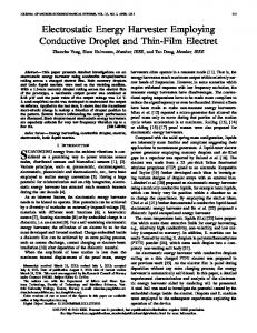
The purpose of this test was to investigate the performance of the existing flight design wires as well as other potential wires and configurations for future use. Two coupon configurations were tested: one coupon simulated the wire topology used at the frontside of the array, and the other at the backside of the array. Different manufacturers and size of wires have been selected to cover a wide range of configurations on a limited size coupon. The wire samples evaluated are shown in Table I. The frontside coupon is shown in Fig. 1. The horizontal wire pairs are the wire pair number 2, 1, 4, 3, 6, and 5. The three vertical wires are 1c, 3c, and 4c. The wire pair 5 is covered with a Kapton sheet to simulate protected wiring. Small glass tapes were placed between overlaying wires. The purpose of the tape was to determine if there is any aging and ESD impact on crossing wires. The wires 2a and 2b have an additional Kapton tube enclosure. Wire set 4 contains charge dissipative surface insulation.
OMBINED environmental exposure testing of a space solar array has been cited as a requirement by the American Institute for Aeronautics and Astronautics [1]. Historically, solar array design qualification consisted of coupon exposure to only a couple of environments of the mission. Until recently, modern solar array designs, as a subsystem, have not been thoroughly subjected to combined environmental exposure tests, which include ultraviolet (UV) radiation,
0093-3813 © 2013 IEEE
3360
IEEE TRANSACTIONS ON PLASMA SCIENCE, VOL. 41, NO. 12, DECEMBER 2013
TABLE I C OUPON W IRE S AMPLES
Fig. 2.
Fig. 1.
Photo of coupon for the front side (coupon front).
B. Coupon for the Back Side (Coupon Back) The wire layout for the backside coupon is nearly the same as the frontside. Only slight differences exist between the two coupons. The backside coupon substrate has a charge dissipative surface, whereas the frontside coupon contains a nonconductive Kapton layer. The sheet that covers wires 5a and 5b are also charge dissipative. Fig. 2 shows the photo of the beginning-of-life (BOL) backside coupon. III. T EST P LAN /T EST E NVIRONMENTS Fig. 3 shows the overall combined environmental test plan. As shown in Fig. 3, there are three main groups of test: BOL, the post 7.5 years that corresponds to middle-of-life (MOL), and the post 15 years that corresponds to endof-life (EOL). The only difference between coupon front (also noted as coupon 3) and coupon back (also noted as coupon 2) is that the UV step is skipped on coupon back.
Solar array test coupon for the back side (coupon back).
Initial Inspection and Bakeout
BOL ESD Test on Coupons 2 and 3
7.5 yr UV Test on Coupon 3
7.5 yr Radiation Test on Coupons 2 and 3
7.5 yr Thermal Cycle Test on Coupons 2 and 3
7.5 yr ESD Test on Coupons 2 and 3
7.5 yr Visual and Electrical Inspection
15 yr UV Test on Coupon 3
15 yr Radiation Test on Coupons 2 and 3
15 yr Thermal Cycle Test on Coupons 2 and 3
Final Visual and Electrical Inspection
Prepare Final Report
Fig. 3.
15 yr ESD Test on Coupons 2 and 3
SPT Test on Coupons 2 and 3
Solar array wire coupon environmental test flow diagram.
A. Test Facility and Environments The testing was conducted at NASA/MSFC. All but thermal cycle testing was performed in facilities of the environmental effects branch. Thermal cycle testing was conducted in the MSFC thermal cycle chamber. The two coupons were initially inspected by both visual and photo documentation, followed by electrical check. Coupons were subjected to thermal vacuum backout at 125 +5/−0 °C for 30 min and 95 +5/−0 °C for 75 h. Then, the BOL ESD tests were performed on each coupon. Fig. 4 shows a diagram of the ESD test chamber. After ESD testing, UV radiation and low-energy proton exposures were performed using separate chambers. Fig. 5 shows a schematic of the UV test facility. A mercury-xenon lamp was used to produce a UV spectrum and is shown in
WONG et al.: ESD TESTS ON SOLAR ARRAY WIRE COUPONS
3361
Cryo-Shroud Wire Coupon
Camera
LN2 Cold Shroud
Faraday Cup Kaufman Ion Source
Electron Flood Gun
Blow-Off Probe
Trek Probe
Electrical Cable
Fig. 4.
2-D Stage
Coupon Movement
Heat Zone
ESD test chamber at NASA MSFC.
Sample Plane UV Window
Fig. 7.
Thermal cycle test chamber at NASA MSFC.
LN2 Input
UV Lamp
LN2 Cold Shroud Front-side Coupon
Table
Photo
Back-side Coupon
Diode
Fig. 5.
Wire Strain Relief
UV test chamber at NASA MSFC. Heat Zone
Enhanced UV Data and AM0 Std. vs. Wavelength 0.01
Irradiance (Watts/cm^2 nm)
1 10
3
Fig. 8. 1 10
1 10
1 10
1 10
1 10
Wire coupons mounted on the thermal cycle chamber.
4
5
6
7
8
400
600
800
1 10
3
Wavelength (nm) AM0-Reference Enhanced UV Source Irradiance
Fig. 6. Simulated UV spectral intensity output measured at three equivalent suns.
Fig. 6. Full light wavelength intensity was achieved from 250 to 500 nm. Above 500 nm, the light intensity was filtered to regulate the sample temperature