the use of COTS (Commercial Off-The-Shelf Components) software has encourages CBSE for the development of business applications [2]. The major benefits ...
International Journal of Computer Applications (0975 – 8887) Volume 90 – No 5, March 2014
Elite Plus – Component based Software Process Model Lata Nautiyal
Neena Gupta, Ph.D
Research Scholar Gurukul Kangri University, Haridwar, India Assistant Professor Graphic Era University, Dehradun, India
Assistant Professor Kanya Gurukul Campus, Dehradun, Gurukul Kangri University, Haridwar, India
ABSTRACT The advancement in the technology has made the user more dependent on information technology, for these information technologies the software serve as the platform. However the rapid growth shown by IT industry also faces challenges of fast growing demand of heavy and complex software systems. In order to fulfill the needs of the end user or to overcome this challenge, software community is moving towards the component based software engineering (CBSE). One of the imperative motivation behind adopting CBSE as software development paradigm is the quick installation of sophisticated and trustworthy software systems with enormous savings, lesser engineering effort, cost, and time. CBSE provides the mechanical facilities that facilitate the easy assemblage and advancement of the software systems out of autonomously developed pieces of the software. The aim of this paper is to present a precise study of the available CBSE lifecycle, and it also proposes a novel CBSE model.
General Terms Software Process Model
Keywords Component Based Development (CBD), Software Development Life Cycle, Elite Plus Model, COTS, Dependency among components
1. INTRODUCTION Component-Based Development (CBD) is currently well established in the IT industry. A component is an encapsulated unit of functionality with a well-defined line that allows it to hook up to other components, and be autonomously deployed. The Component-based applications are distinct from the assembling components. The Component-Based Software Engineering (CBSE) has become apparent [1] in the starting of 1990’s. Initially, the applications developed by CBSE were limited to PCs whereas the use of COTS (Commercial Off-The-Shelf Components) software has encourages CBSE for the development of business applications [2]. The major benefits associated with component-based technologies include: development of condensed system, quick installation, reduced cost, enhanced quality, and condensed system evolution and less maintenance cost. The increase in time has given rise to the development of standard component-based specifications and the importance of CBD has grown rapidly in the embedded system trade. A component is said to be a self-contained bit of software if it has an open interface, delivers clear functionality and moreover gives plug-and-pay services. Therefore it can be stated that component-based software development promotes
the reusability and gives improved software quality. Thus Component-based software development can lead to new ideas for the construction of large and complex software systems.
2. REVIEW OF LITERATURE The different kind of CBSD models can be seen in the industry as well as in the academia. We referred to some of them; in this section some of them are discussed that are as follow: The term CBSE has actually come into the existence after COM+ [3] from Microsoft, Enterprise JavaBeans [4] from SUN, and IBM Component Broker [5] and CORBA [6]. CBSE have made way among the conventional software technologies [7]. Additionally, incremental delivery of software attributes or platforms that comprise a software product line is expected to be at the forefront in the upcoming years, therefore component-based software engineering has implications for how software engineers attain, assemble and sustain software systems [8]. Thus, we should see drastic changes in designers’ primary roles and required skills for software development in the upcoming time. A Software Life Cycle Model is an expressive and illustrative depiction of all different stages of the software process. Software development life cycle (SDLC) model depicts the phases of the software development cycle [9]. The Twin Peaks model [10] also suggest for a parallel, continual development of requirements and architecture all through development. It presents a partial and easy way to develop the software. In X Model, the mechanisms are started by requisite engineering and requirement measurement. The main characteristic of this software life cycle model is reusability in which software is developed by building reusable components and software development from reusable and testable components. In software development, it uses two main ways, develop software component for reuse and software development with or without modification in reusable component. [11] The Y Software Life Cycle Model represents software reusability during CBSD. The Y Shape of the model contemplates iteration and overlapping. Although the main phases may overlap each other and iteration is allowed, the designed phases of this model are: domain engineering, frame working, assembly, archiving, system analysis, design, implementation, testing, deployment and maintenance. [12]. Knot Model highlighting on reusability, considering risk analysis and feedback in each and every segment. This model may be best matched for intermediate or larger complex system’s development. It is based on three states of the component [13].
1
International Journal of Computer Applications (0975 – 8887) Volume 90 – No 5, March 2014 The Elite Life Cycle Model (ELCM) is an promising software lifecycle model for the expansion of new product using component based technology. This model describes a general process of Software development with the help of in built components. [14]. New Era with new Innovation in Software Development [15] gives the concept of selection, prioritization and customization to develop, modify and selection of components. The V model adopted the traditional software development approach for building a system from reusable software components [16]. It consists of several steps and provides the details information at the design phases. The main emphasis of V-Development is component development lifecycle. Component development lifecycle was considered as different process. The selection phase gets input from the separate system that usually finds and evaluates the suitable components to be composed into the system. The V Model is an adaptation of the rigid traditional waterfall model for modular system development with little flexibility. Two V models have conjoined, one for component life cycle and one for system lifecycle in the W lifecycle model Component based development process comprise of a component life cycle and a system life cycle, and it is the base of W lifecycle model [17]. The W model fulfils all the requirements of component based development. The W Model accommodates a V model for both component and system life cycles.
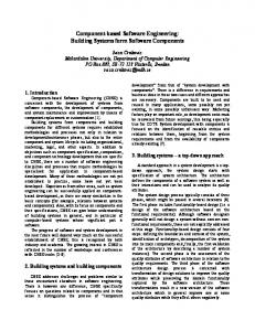
3. PROPOSED MODEL – Elite Plus Some of the popular State of art has been discussed in our literature review section. From the literature review we came to the conclusion that all CBSD lifecycle have some drawbacks and there is a need of a new lifecycle for component based software development. Figure 1.1 shows details of our proposed improved CBSD Model. Reusing of existing components is an important concern of the Component Based Software Development. These reusable components can be previously done system requirement, architecture, testing and implementation. The core phases of our improved CBSD model are
A. B. C. D. E. F. G.
Prerequisite: Risk analysis: Engineering: Test – Integration - Test: Version: Customer evaluation: Deliver:
Each phase (figure 1) will be a deliverable “versions” of the software. (Ex: a Microsoft Word delivers basic file management editing, in the first increment; more sophisticated editing, document production capabilities in the 2 nd version; spelling and grammar checking in the 3rd version. When this model is applied, the 1st version is often a core product. The core product is used by the customer. As a result of use and / or evaluation, a plan is developed for the next version. The plan addresses the amendment of the core product to better meet the requirements of the customer and the delivery of supplementary features and functionality. The process is continual following the delivery of each version, in anticipation of the complete product is produced. If the customer demands delivery by a date that is not viable to meet, suggest delivering one or more version by that date and the rest of the software afterward.
3.1 Prerequisite The prerequisite phase involves moving out enough business/application/system modeling to describe a consequential build scope. A build delivers a well-defined set of business functionalities that end-users can use to do real work. The most complicated tasks are to identifying the real difficulty of the existing system. Without clear thoughtful of the problem in the system, any further work prepared will lead to depletion of effort at a later stage. The capacity of a build is not an arbitrary selection, but rather a logical selection that satisfies particular development objectives. This phase defines the user requirements, or what the user expects from the system. This phase as well sets the project restrictions, which define what parts of the system, can be changed by the project and what parts are to stay without any transform. This also includes a coarse idea of the resource necessities for the project as well as the predictable start and achievement dates for each phase and the number of persons expected to be occupied in every phase. In this model requirements are gathered or elicited on the basis of their availability. We can begin the development of software considering the available/explored requirements and can consider or add new requirements in the next version of the software. It may be possible that customer cannot explore all the requirements in the beginning and may reveal new requirements after getting some initial working versions of the software. In this model we have considered the properties of incremental approach.
2
International Journal of Computer Applications (0975 – 8887) Volume 90 – No 5, March 2014
Elite Plus - Component Based Software Process Model Prerequisite
Prerequisite
Prerequisite
Prerequisite
Risk Analysis
Risk Analysis
Risk Analysis
Risk Analysis
Engineering
Engineering
Engineering
Engineering
Integration
Integration
Integration
Integration
Test
Test
Test
Test
Version I
Version II
Customer evaluation
Customer evaluation
Customer evaluation
Customer evaluation
Deliver
Deliver
Deliver
Deliver
Version N
Version Final
Fig 1: Elite Plus – The Proposed Model This phase will cover up:
Analyzing the problems and problem area.
Prioritize the difficulty (domain).
Gathering/Exploring available requirements.
Prioritization of requirements on the basis of customers demand.
Frame working of proper system goals according the problem main concern.
Risk Analysis is done not only for newly developed components, but it must consider COTS components. It defines the reliability and maintainability of individual components. Input to this phase is the basic architecture drawn from the Requirement phase. After the risk assessment we can go for engineering phase. If there is enough risk involved in development either we can ask some third party to develop that component or we can postpone the development till its mitigation.
Determining the boundaries of the project.
The main objective of the Risk Analysis process is to:
Project initialization on the basis of available requirements.
Focus concentration on minimizing threats in order to accomplish the project objectives by:
3.2 Risk analysis
Any unforeseen event which makes the software over budget and over run can be defined as a Risk.
Fulfilling a high-level evaluation of project risk with all project stakeholders.
Make available a organized approach for detail risk analysis and appraisal by:
Identifying and assessing risks.
Determining effective risk reduction actions.
Tracking and reporting improvement in reducing risk.
We have included Risk Analysis in our model to provide reliability as well as long term maintainability. All the risks are identified and resolved in this phase. This activity should be included in every new and incremented version of the software.
3
International Journal of Computer Applications (0975 – 8887) Volume 90 – No 5, March 2014
3.3.2
1.
Spot the risks - Comprehend the classic problems that might adversely affect the project.
2.
Measure the risks - Rank the risks in order of significance based on likelihood of occurrence, impact of occurrence, and degree of risk conviction.
3.
Plan the risk response – Evaluate risk assessment alternatives and amend the project management plan and project agenda to adjust for the risk.
4.
of each method is recognized, the component can be designed and implemented.
Risk Management Process Methodology
The risk management process methodology involves four basic steps:
Monitor the risks – All through the project, carry on to revisit the risk profile, re-evaluate main risks, and update the risk profile with action taken.
4.
Outsourcing of Risky Component – At times it is not practicable to reuse COTS components or the development of new components since some risk factor may be involved, or we need some portion of a component for very short span of time. In such cases some third party components may be outsourced.
3.3.2.1 Engineering Repository
of
1.
Independent
The most constructive phase of the component based development is engineering. This phase presents real challenge to the software engineers. The basic architecture of the software is developed. Architecture defines the basis of integration of components. On the bedrock of architecture we then engineer our components. Engineering phase can be divided into two sub-phases:
2.
Single level Dependency
3.
Multi level Dependency
4.
Multiple Dependencies
1.
Independent
Architecture Engineering
Architecture provides blueprint for the selection and integration of components. Architecture engineering emphasizes on dividing the software problem in smaller, function oriented units and then providing these units to identify suitable components. It defines the:
Nature of Communicating interfaces for user as well as for components.
Nature and number of Internal and External input sources like entities, events, scenarios, etc.
Nature and number of Internal and External Output consumers like entities, events, scenarios, database, etc.
Functions and characteristics provided by the proposed software (i.e., on the basis of Functional and Non Functional requirements).
3.3.2
Component Engineering
The output of Architecture Engineering phase provides the input to the Component Engineering. On the basis of modular units identified, we can engineer components. It includes:
3.3.2.1 Traditional methods of CBSE engineering 1.
Off the shelf components – Once a build range is established, we need to make a decision which of the requisite components can be used (e.g., already exist in the organization or can be bought off-the-shelf) and which ones necessitate to be developed.
2.
Modify Existing Components (if required) – Developing a novel module from the scrape is always avoided in component based development. It may extremely be possible that some obtainable components may require some minor or major modifications to accommodate with other components.
3.
Engineering of New individual Component – Developing a new component should forever begin with defining the component interface. This represents a permanent agreement between the component and other components. Once the interface is distinct and the intent
from
During the component engineering, we can identify components in accordance with the problems suitability. We can define components in a hierarchical structure. According to its dependency on other components, a component may be: Sovereign
3.3 Engineering
3.3.1
Components
Expected Output
Independent Component
Desired Input
No changes required
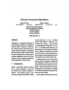
Fig 2: Independent Components 2.
Single level Dependency
Component 1
Changes in Component1 to make Compatible with Component 2
Single Level Dependency Component 2
Changes in Component2 to make Compatible with Component 1
Component 1 is dependent on Component 2 for the desired functionality, so changes in both are necessary.
Fig 3: Single level dependency among components
4
International Journal of Computer Applications (0975 – 8887) Volume 90 – No 5, March 2014 3.
Multi level Dependency Component 1 (Unit Testing) Changes in Component1 to make Compatible with Component 2
Component 1
Multi Level Dependency
Component 2
Component 2
+ Component 2
Changes in Component2 to make Compatible with Component 1 and Component 3
(Unit Testing)
Changes in Component3 to make Compatible with Component 2
(Unit Testing)
Design Architecture
Architecture Based Integration
Next Phase
Component 3
Regression Testing
Component 1 is dependent on Component 2 for the desired functionality, and the Component 2 is dependent on Component 3,
Component N
so changes in all three are necessary.
(Unit Testing)
4.
Tested Components
Multiple Dependencies
Fig 4: Multi level dependency among components Changes in Component1 to make Compatible with Component 3
Unit Testing
Changes in Component2 to make Compatible with Component 3
Fig 6: Testing and Integration Process 1.
Unit Testing of Off-the-shelf components: Black Box testing to test the behavior of the individual component. If it provides desired result, it may be reused.
2.
Unit Testing of Modifiable Components: Testing to test the behavior of the individual component. If it provides desired result, it may be reused, and if certain changes are necessary to make it compatible in problems context, White box testing is done to certify the structure of the modified cod.
3.
Unit Testing of New Components: New components are developed from the scratch in accordance with the user requirement. So behavior and the structure both need testing.
4.
Unit Testing of Outsourced Components: Black Box testing is done to check the behavior of the outsourced component.
Component 2
Component 1
Multiple Dependencies
Component 3
Changes in Component3 to make Compatible with Component 1 and Component 2
Fig 5: Multiple dependencies among components
3.4 Test – Integrate- Test Testing is done with the intent of finding errors present or likely to present in individual components or in integrated system. Off the shelf components are pre-tested, so we have to look their compatibility with other components in the context of proposed software. Bendable components may introduce new bugs after making some changes in their code. Since changes are necessary to make them usable in proposed solution context (see figure 6). They need Unit testing as well as regression testing to eliminate errors. We need Unit testing and Regression testing for newly developed components. We suggest different testing techniques for these components, as:
Test-Integrate-Test
After the testing of individual components, they are integrated to achieve the desired software. Their integration will be supported by the architecture of the software designed in the Engineering phase. When two or components are integrated, some changes must be done to make compatibility among them. Regression testing is the procedure of retesting the personalized parts of the component and ensuring that no new errors have been introduced into previously tested component code. The benefit of using regression testing is that we can reuse the test suite that was used to test the original version of the component and the software. Re-running of all test cases in the test suite is not required. This will reduce the effort of testing and the overall cost of testing. We can minimize the number of test cases by applying minimizing techniques.
5
International Journal of Computer Applications (0975 – 8887) Volume 90 – No 5, March 2014
3.5 Version The version can serve as the “first system”. Together customers and developers be fond of the prototyping paradigm as users get a feel for the actual system, and developers get to build Software immediately. Yet version can be challenging: The developer makes implementation compromises in order to get a version functioning rapidly. An inappropriate operating system or programming language used simply because it’s available and known. After a point in time, the developer possibly will become contented with these choices and forget all the reasons why they were inappropriate. The key is to describe the rules of the game at the beginning. The customer and the developer must mutually have the same opinion that the version (trial product) is built to serve as a mechanism for defining requirements.
3.6 Customer Evaluation This is approximately the end of system development, now the system is prepared to be presented to the customer. However, deployment involves more than putting the system into place, it is the time when users should be helped to appreciate and feel comfortable with the software. If deployment is not successful, users will not make the most of the system and may be unhappy with its performance. In either case, users will not be as creative or effective as they could be and the care taken to build a premium system is put in hazard. The two key issues to successful transfer from the developer to the user are documentation should sketch and come up with aids that help users learn about the system, such as on-line help. Supplementary the system is documentation and manuals to which users refer for problem solving, trouble shooting or further information. The quality and type of documentation can be serious, not only to training, but also to the accomplishment of the system. Training for users and operators is based primarily on major system functionality; there is no need to be aware of the system’s internal operation. As a result, system deployment be well thought-out with more care and professionalism than it has been usually dealt with.
3.7 Deliver Deployment and Release is a form that can be installed on the target machine.
4. CONCLUSION All the software life cycle models have their own advantages and disadvantages. In this paper, we have reviewed a number of commotion areas that form a life cycle framework for component-based software development. The Elite Plus model supports “development with reuse” through component congregation, as well as “development for reuse” through component archiving. Initially, the software engineer identifies likely reusable components from accessible reusable libraries. The components are then chosen, modified and reused through composition, generalization and specialization mechanisms. At the end of software development, there may be many new reusable components that need to be established, catalogued, classified and then stored into reusable libraries. The proposed ELITE PLUS model covers the likely phases of large software development and enforces software reusability along its phases. We have introduced a new concept of Engineering of Components from Repository. We have defined components in a hierarchical structure.
We hope the proposed model with come out with the motto to help the software community to develop the cost effective and risk free software in CBSE environment.
5. ACKNOWLEDGMENTS From the core of my heart, I am really thankful to the Management of Graphic Era University for always being supportive. I would also like to express my gratitude to the management of Gurukul Kangri University for providing such a commendable research oriented platform to us.
6. REFERENCES [1] C. Szyperski, Component Software, Addison-Wesley, 1998. [2] M. Aoyama, Componentware: Building Applications with Software Components, J. of IPSJ, Vol. 37, No. 1, Jan. 1996, pp. 71-79 (In Japanese). [3] Microsoft, 2004. COM+, http://www.microsoft.com/com/tech/complus.asp. [4] SUN, 2004. Enterprise Java Beans, http://www.java.sun.com/products/ejb/index.html. [5] IBM, 2004. Component http://www.software.ibm.com/ad/cb.
Broker,
[6] Object Management Group, 2004. The Common Object Request Broker Architecture, http://www.omg.org. [7] Wallnau, K. C., S.A. Hissam and R.C. Seacord,2002. Building Systems from Commercial Components. Addison-Wesley. [8] Clements, P. and L. Northrop, 2002. Software Product Lines. Addison-Wesley. [9] S. Cohen, D. Dori, U. de Haan, “A Software System Development Life Cycle Model for Improved Stakeholders Communication and Collaboration”, International Journal of Computers, Communications & Control,Vol. V (2010), No. 1, pp. 20-41 [10] Royce, W.W., 1987. “Managing the development of large software systems”. Proceedings of 9th IEEE International Conference on Software Engineering, pp: 328-338. [11] Gill N. S. and Tomar P., “X Model: A New ComponentBased Model”, MR International Journal of Engineering and Technology, 2008, Vol. 1, No. 1 & 2, pp. 1-9. [12] Luiz Fernando Capretz, " Y: A new Component-Based Software Life Cycle Model ", Journals of Computer Science1 (1) : pp.76-82. [13] Rajender Singh Chhillar, Parveen Kajla, “A New Knot Model for Component Based Software Development”, International Journal of Computer Science Issues Year: 2011 Vol: 8 Issue: 3 Pp.: 480-484 [14] Lata Nautiyal, Umesh Kumar Tiwari, Sushil Chandra Dimri, Shivani Bahuguna, “Elite: A New ComponentBased Software Development Model”, International Journal of Computer Technology & Applications (IJCTA), Vol 3, Issue 1, Jan 2012, pp 119-124 [15] Lata Nautiyal, Umesh Tiwari, Sushil Dimri & Shashidhar G. Koolagudi, “Component based Software Development- New Era with new Innovation in Software Development,” International Journal of Computer
6
International Journal of Computer Applications (0975 – 8887) Volume 90 – No 5, March 2014 Applications (IJCA), vol. 51, no. 19, pp. 5-9, August 2012
Component Lifecycle.” Online Available: http://www.mrtc.mdh.se/publications/0953.pdf
[16] Ivica Crnkovic; Stig Larsson; Michel Chaudron, “Component-based Development Process and
[17] The W Model for Component-based Software Development [online]. Online Available: http://www.cs.man.ac.uk/~kung-kiu/pub/seaa11b.pdf.
IJCATM : www.ijcaonline.org
7