End-User Software Visualizations for Fault Localization J. Ruthruff, E. Creswick, M. Burnett, C. Cook, S. Prabhakararao, M. Fisher II, M. Main Oregon State University Department of Computer Science {ruthruff, creswick, burnett, cook, prabhash, fisherii, mainma}@cs.orst.edu user environment is the spreadsheet. Evidence from the spreadsheet paradigm reveals that, despite the perceived simplicity of this kind of end-user programming, end-user programmers create a disturbing number of faults [Panko 1998]. Perhaps even more disturbing, spreadsheet developers often express unwarranted confidence in the reliability of their spreadsheets [Panko 1998].
Abstract End-user programming has become the most common form of programming today. However, despite this growth, there has been little investigation into bringing the benefits of software visualization to end-user programmers. Evidence from the spreadsheet paradigm, probably the most widely used end-user environment, reveals that end users’ programs often contain faults. We would like to integrate software visualization into these end-user environments to help end users deal with the reliability issues in their programs. Towards this end, we have devised several fault localization visualization techniques for spreadsheets. This paper describes these techniques and reports the results of a formative study—using tests created by end users—to investigate how these fault localization techniques compare. Our results reveal some strengths and weaknesses of each technique, and provide insights into the cost-effectiveness of each technique for the interactive world of end-user spreadsheet development.
To help solve the problem of pervasive faults in end-user programming, we have been working on a vision we call “end-user software engineering,” prototyping our ideas in the spreadsheet paradigm because it is so widespread in practice. The concept of end-user software engineering is a holistic approach to the facets of software development in which end users engage. Its goal is to bring some of the gains from the software engineering community to end-user programming environments, without requiring training or even interest in traditional software engineering techniques. Much of our communications strategy with end-user programmers is done via incremental software visualization. As part of this vision, we have previously devised a testing methodology known as “What You See Is What You Test” (WYSIWYT) [Rothermel et al. 1998]. The WYSIWYT methodology communicates the “testedness” of each spreadsheet cell via incremental, low-cost visualization devices such as border colors. It responds to the user’s actions and after each action relevant to testing, updates the visualization devices. The use of visualization devices that are low in cost is obviously required to maintain the immediate response expected by spreadsheet users.
CR Categories: D.2.5 [Software Engineering]: Testing and Debugging–debugging aids, testing tools. D.2.6 [Software Engineering]: Programming Environments–interactive environments. D.1.7 [Programming Techniques]: Visual Programming. H.4.1 [Information Systems Applications]: Office Automation–spreadsheets. Keywords: end-user software engineering, end-user programming, end-user software visualization, fault localization, spreadsheets
Given this explicit, visualization-based support for testing, it is natural to consider leveraging it to help users with fault localization once one of their tests reveals a failure1. But what is the best way to proceed? There are many issues to consider in answering this question, and we will not try to enumerate them all, but two important issues are:
1 Introduction End-user programming environments are becoming a widespread phenomenon. It is estimated that by the year 2005 there will be approximately 55 million end-user programmers in the U.S. alone, as compared to only 2.75 million professional programmers [Boehm et al. 2000]. However, to date, there has been little investigation into bringing the benefits of software visualization to end-user programmers.
Effectiveness: What techniques will do an effective job at visually isolating the faults, given whatever correct and incorrect values (failures) an end user has been able to identify via testing?
Although end-user programming environments are quite diverse, including educational simulation builders, web authoring systems, multimedia authoring systems, e-mail filtering rules, CAD systems and more, in practice, probably the most widely used end-
Cost: Can any such techniques be low enough in cost to maintain the incremental, immediate response expected in the spreadsheet paradigm? In this paper, we attempt to shed some light upon these questions. We compare a technique previously described in the literature [Reichwein et al. 1999], which we will refer to as the “Blocking Technique,” with two new techniques of ours, presented here. For
Copyright © 2003 by the Association for Computing Machinery, Inc. Permission to make digital or hard copies of part or all of this work for personal or classroom use is granted without fee provided that copies are not made or distributed for commercial advantage and that copies bear this notice and the full citation on the first page. Copyrights for components of this work owned by others than ACM must be honored. Abstracting with credit is permitted. To copy otherwise, to republish, to post on servers, or to redistribute to lists, requires prior specific permission and/or a fee. Request permissions from Permissions Dept, ACM Inc., fax +1-212-869-0481 or e-mail
[email protected]. © 2003 ACM 1-58113-642-0/03/0006 $5.00 ACM Symposium on Software Visualization, San Diego, CA
1
123
Following standard terminology, in this paper we use the term “failure” to mean an incorrect output value given the inputs, and the term “fault” to mean the incorrect part of the program (formula) that caused the failure.
similar to xSlice called Tarantula [2002]. Unlike xSlice, Tarantula utilizes information from all passing and failing tests when highlighting possible locations for faults. It colors the likelihood that a statement is faulty according to its ratio of failing tests to passing tests.
each, we describe their basic logic and the costs they add to the spreadsheet paradigm. We then describe the results of a formative empirical study of the techniques’ effectiveness at finding faults, in which the subjects were test suites created by end users.
2 Related Work
Tarantula and xSlice both focus on helping professional programmers find faults in programs developed in traditional programming languages. Our work differs in that we are trying to assist end users in finding faults in the spreadsheets they develop. Additionally, Tarantula and xSlice both report on the results of testing after running the entirety of a test suite and collecting information from all of the tests in the test suite. Our techniques incrementally update information about likely locations for faults as soon as the user applies tests to their spreadsheet.
There has been a variety of software visualization work aimed at software engineering purposes. We focus here on the portion of it that is related to debugging. The FIELD environment [Reiss 1998] was aimed primarily at program comprehension as a vehicle for both debugging and instruction, and included visualizations of call graphs, heap behavior, I/O, class relationships, and so on. This work draws from and builds upon earlier work featuring visualizations of code, data structures, and execution sequences, such as PECAN [Reiss 1984], the Cornell Program Synthesizer [Teitelbaum and Reps 1981], and Gandalf [Notkin et al. 1985]. ZStep [Lieberman and Fry 1998] aims squarely at debugging, providing visualizations of the correspondences between static program code and dynamic program execution. Its navigable visualizations of execution history are representative of similar features found in some visual programming languages such as KidSim/Cocoa/Stagecast [Heger et al. 1998] and Forms/3 [Atwood et al. 1996; Burnett et al. 2001]. An example of visualization work that is especially strong in low-level debugging such as memory leaks and performance tuning is PV [Kimelman et al. 1998]. Low-level visualization work specifically aimed at performance debugging in parallel programming is surveyed in [Heath et al. 1998]. Finally, Eick’s work focuses on high-level views of software, mostly with an eye to keeping the bugs under control during the maintenance phase [1998].
Pan and Spafford developed a family of heuristics appropriate for automated fault localization [1992]. They presented a total of twenty different heuristics that they felt would be useful. These heuristics are based on the program statements exercised by passing and failing tests. For example, one of their heuristics indicates all statements exercised by failing tests in the test suite (a set that is highlighted by all of our techniques). Our techniques directly relate to three of these heuristics, the set of all cells exercised by failed tests, cells that are exercised by a large number of failed tests, and cells that are exercised by failing tests and that are not exercised by passing tests. We combine these heuristics to determine the likelihood that a cell contains a fault.
3 WYSIWYT: The Setting for Fault Localization The underlying assumption behind the WYSIWYT testing methodology [Rothermel et al. 1998] is that, as a user incrementally develops a spreadsheet, he or she is also testing incrementally. Because the intended audience is end users, all communication about testing is done through software visualization devices. The incremental and interactive nature of spreadsheets requires these visualization devices to be incremental, as well as efficient enough to maintain immediate visual feedback.
The above techniques aim to help the programmer understand the program’s behavior so that he or she can debug it. In contrast to these, most fault localization visualization techniques have two phases. The first phase, the fault localization phase, finds ways to help the system to understand possible sources of bugs, in part by using information provided by the programmer in the process of testing. The second phase then communicates its new understanding back to the programmer in the form of visualizations.
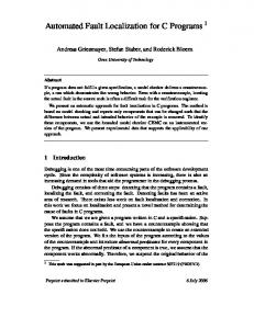
Figure 1 depicts a simple example of WYSIWYT in Forms/3 [Burnett et al. 2001; Burnett and Gottfried 1998], a spreadsheet language that utilizes “free-floating” cells rather than a traditional spreadsheet grid. With WYSIWYT, all untested cells have red borders (light gray in this paper). For example, cell Net_Amount in Figure 1 has never been tested and its border is red (light gray). When a user notices that a cell’s value is correct, they can check it off (√) in the checkbox at the corner of the cells, such as the one in cell Withholdings. In response to this action, visualizations are updated at three granularities.
Many fault localization techniques build on the significant research into slicing and dicing. Tip provides a survey of slicing techniques in [Tip 1995]. In general a program slice relative to variable V at program point P is the set of all statements in the program that affect the value of V at P. If the value of V is incorrect at point P in the program for a given test case, then, under certain assumptions, it can be guaranteed that the fault that caused the incorrect value is in the slice. These slices can be calculated using entirely static information, or can often be more precisely calculated using dynamic information. A dice is similar to a slice [Chen and Cheung 1997]. The difference is that it utilizes information about correct values of V at other program points to further reduce the set of statements that could be responsible for the incorrect value of V.
At the granularity of cells, the checkmark appears, indicating that the cell’s current value is the result a successful test. The cell border colors of the checked-off cell and cells contributing to it move along a continuum from red (untested) to blue (tested; black in this paper). In the figure, cell Withholdings is half way along this continuum, but Overtime_Pay and Gross_Amount, which contribute to it, are completely blue (black). If the user elects to show a cell’s dataflow arrows, its incoming arrows follow the color scheme of its borders, as with cell Overtime_Pay.
Building upon this work, Agrawal et al. presented a technique for locating faults in traditional programming languages using execution traces from tests, and implemented this technique in the xSlice tool [Telcordia Technologies 1998]. This technique is based on displaying dices of the program relative to one failing test and a set of passing tests. Jones et al. developed a system
124
Figure 1. WYSIWYT has been implemented in the research spreadsheet language Forms/3. (Left) A Forms/3 spreadsheet illustrating WYSIWYT’s low-cost visualization features. (Right) The bird’s eye view of all spreadsheets in memory. they have trouble conjuring up a suitable input, an automatic test generator will suggest some [Fisher et al. 2002].
The user has elected to show some cells’ dataflow arrows as well as some cells’ formulas, and this allows a finer granularity of visualization. The dataflow arrows connecting the formulas’ subexpressions follow the same color scheme at the granularity of subexpressions, which shows users the untested cell reference combinations that still need testing.
The visual fault localization techniques we investigate in this paper were all prototyped in the context of WYSIWYT. However, the techniques do not require the entire WYSIWYT methodology. Rather, the minimum entry point to these techniques is any spreadsheet language that adds a checkbox allowing a user to check off a correct cell value.
Finally, there are two visualizations at the granularity of spreadsheets. The first is the “testedness” indicator at the top right of the spreadsheet, showing that overall the spreadsheet is 61% tested. Second, the bird’s eye view at the right of Figure 1 shows the testedness of every spreadsheet currently loaded in memory.
4 Three Fault Localization Visualization Techniques
Although the user may not realize it, behind the scenes “testedness” is computed using a dataflow test adequacy criterion [Laski and Korel 1993; Ntafos 1984; Rapps and Weyuker 1985]. A test adequacy criterion sets standards describing when software (in this case, a spreadsheet) has been adequately tested. Such a criterion is necessary in a testing methodology because we must, at some point, define when the user has done “enough” testing.2
While incrementally developing a spreadsheet, a user can indicate his or her observation of a failure by marking a cell incorrect with an “X” instead of a checkmark. At this point, our fault localization techniques highlight in varying shades of red the cells that might have contributed to the failure, with the goal that the most faulty cells will be colored dark red. How should these colors be computed? Computing exact fault likelihood values for a cell, of course, is not possible. Instead, we must combine heuristics with deductions that can be drawn from analyzing the source code (formulas) and/or from the user’s tests.
WYSIWYT’s adequacy criterion is du-adequacy. A definition is a point in the source code where a variable (cell) is assigned a value, and a use is a point where a variable’s value is used. A definition-use pair, or du-pair, is a tuple consisting of a definition of a variable and a use of that variable. A du-adequate test suite, which is based on the notion of an output-influencing all-definition-use-pairs-adequate test suite [Duesterwald et al. 1992], is a test suite that exercises each du-pair in such a manner that it participates (dynamically) in the production of an output explicitly validated by the user.
Because these techniques are meant for highly interactive visual environments, we are interested in cost-effectiveness. In this section, we describe three techniques, their information basis for making deductions, the properties each maintains in drawing further inferences from these deductions, and how much each technique’s reasoning costs.
Thus in Figure 1, the Withholdings cell is only 50% tested because only one of the two du-pairs in that cell have been tested. Because the dataflow arrows are showing, exactly which du-pairs still need to be tested is explicitly shown. The user has hovered the mouse over one of the medium-gray arrows for an explanation. (We consider explanations to be critical in an end-user environment, because most end users will not have had prior training in software engineering practices.) The user’s next step could be to try an input that will allow them to test untested du-pairs. If 2
The better the information, the higher the cost, but the higher the ability of the visualization to visually emphasize the faulty cells—at least, this was our starting premise in devising these techniques. We will test this premise in Section 6.
4.1 The Test-Count Technique The technique we term the Test-Count Technique bases the fault likelihood of a cell on the number of successful tests (those which the user marked with a √) versus the number of failed tests (those which the user marked with an X) in which that cell has participated. This technique’s information basis is much the same as in
Of course, an adequately tested spreadsheet cannot guarantee that the spreadsheet is fault-free.
125
Tarantula [Jones et al. 2002]; however it differs from Tarantula in that our algorithms are incremental and that our visualization aims at end-user programmers, not professional programmers. We will use producer-consumer terminology to keep dataflow relationships clear; that is, a producer of C contributes to C’s value, and a consumer of C uses C’s value. In slicing terms, producers are all the cells in C’s backward slice, and consumers are all the cells in C’s forward slice. C is said to participate in a test (or to have a test) if the user has marked (with a √ or an X) C or any of C’s consumers. Expressed in these terms, our Test-Count Technique uses information about successful and failed tests to maintain the following three properties:
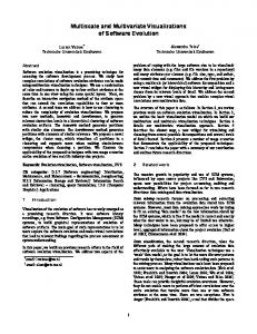
Figure 2. The hypothetical Paycheck spreadsheet with a fault in the Overtime_Pay cell. The Test-Count Technique is visually assisting the user’s effort to localize the fault contributing to the failures he or she has observed.
Property 1: If cell C or any of its consumers have a failed test, then C will have non-zero fault likelihood.
Regular_Pay, Overtime_Pay, and Gross_Amount to be estimated at Medium while Withholdings and Net_Amount have been estimated at Low. Finally, the user hovered the mouse over Overtime_Pay to see an explanation of its visualization. Figure 2 is a simple example in order to clearly illustrate the differences in fault likelihood visualizations among our three techniques.
This first property ensures that every cell that might have contributed to the computation of an incorrect value will be assigned some positive fault likelihood. Property 2: The fault likelihood of C is proportional to the number of C’s failed tests.
This technique came about by leveraging algorithms and data structures that were written for another purpose—to support semiautomated test re-use (regression testing) in the spreadsheet paradigm [Fisher II et al. 2002]. The algorithms and data structures are detailed in that paper. Here, we summarize the information stored in those data structures. We then consider the costs of the Test-Count Technique under two settings: first, given the existence of the test re-use feature in the environment (as is the case in our prototype), and second, a “bare” spreadsheet language that has only checkboxes for recording faults.
This property is based on the assumption that the more incorrect calculations a cell contributes to, the more likely it is that the cell contains a fault. Property 3: The fault likelihood of C is inversely proportional to the number of C’s successful tests. The third property, in contrast to Property 2, assumes that the more correct calculations a cell contributes to, the less likely it is that the cell contains a fault.
There are three basic interactions3 the user can perform that could affect these properties. Each interaction potentially triggers activity by the technique. The interactions are: users might change a constant cell’s value (analogous to running with a different input value), users might change a non-constant cell’s formula, or users might add another test by checking off or X’ing out a cell’s value.
To implement these properties, let NumFailingTests(C) (NFT) be the number of C’s failed tests, and let NumSuccessfulTests(C) (NST) be the number of C’s successful tests. If a cell C has no failed tests, the fault likelihood of C is None. Otherwise, the fault likelihood of a cell C is calculated as follows:
Under the first setting, the test re-use data structures already maintain the necessary information about previous tests. In this setting, changing a constant value to another constant value does not trigger any activity. This is because the WYSIWYT methodology does not define a new execution to be a new test; only a √ or an X mark by the user defines a set of values to be a test. Changing C’s non-constant formula incurs an additional time cost of O(1); the data structures are already reinitialized by the regression testing subsystem, but C and its consumers must be recolored. The added cost to recolor is only O(1) because these cells must already be visited to update their values and “testedness” border colorings. Finally, when the user enters a
fault likelihood(C) = max(1, 2 * NFT – NST) This calculation is mapped to one of four possible fault likelihood ranges: a value of 1 or 2 maps to the fault likelihood Low, 3 or 4 maps to Medium, 5-9 maps to High, while anything above 10 maps to Very High. Consider the spreadsheet in Figure 2. Overtime_Pay has a fault: Wage should be multiplied by 1.5 times Overtime_Hrs. This spreadsheet’s user has indicated (with an X) his or her observation of a failure in both the Gross_Amount and Net_Amount cells, as these cells contain incorrect values for the given inputs. Furthermore, the user has indicated (with a √) that the value contained in Regular_Pay is correct. Using this information and the dataflow relationships, the Test-Count Technique has assigned an estimated fault likelihood, visually represented by varying shades of red (gray in this figure), to each non-input cell in the spreadsheet. Specifically, the visualization shows the fault likelihood of
3
126
Variations on these interactions also trigger activity. For example, removing a test (undo’ing a checkmark) triggers action that reverses the changes made by placing the checkmark. However, we will usually ignore these variations, because they are obvious and do not add materially to this discussion.
mark, the additional cost is O(1): the system needs to update the test counts and colorings of C and its producers, but these cells must already be visited given the testing subsystem to update the border colorings. Thus, given the presence of the regression testing subsystem reported in [Fisher II et al. 2002], the highest additional cost of this fault localization subsystem for any trigger is only O(1), showing the Test-Count Technique to be extremely reasonable in cost in this setting.
Property 5: A checkmark on C blocks the effects of any X marks on C’s consumers (forward slice) from propagating to C’s producers (backward slice), with the exception of the minimal fault likelihood property required by Property 1. Similar to Property 4, this property uses checkmarks to prune off C’s producers from the highlighted area if they contribute to only correct values, even if those values eventually contribute to incorrect values.
Now consider the other setting, a bare spreadsheet language with only checkboxes for entering decisions about whether a test was successful or has failed. Because of the responsiveness requirements of spreadsheet languages, we have chosen to trade space to save time whenever possible, storing relationships between cells and tests in both directions. Given these data structures, the users’ interactions trigger the same algorithms as presented in [Fisher II et al. 2002] for test re-use purposes, plus the work just described for the setting in which those algorithms already existed. Thus, we simply add in the time complexities for the test re-use algorithms. As discussed in that work, after a user enters a mark in cell C, the affected information stored about tests is updated in O(up) time where u is the maximum number of uses of (references to) any cell in the spreadsheet, and p is the number of C’s producers. Changing cell C’s non-constant formula to a different formula requires all saved information about C’s tests and those of its consumers to be considered to be obsolete. For the same reason, C’s and its consumers’ fault likelihoods must all be reinitialized to zero. All of the related testing information can be updated in O(mc* max(u, cost of set operations)), where m is the number of marks (tests) that reach the modified cell, c is the maximum number of consumers affected by C’s tests, and u is still the maximum number of uses for any cell in the spreadsheet. Clearly, in this setting, the Test-Count Technique’s costs may be an issue to responsiveness.
To implement these properties, let NumBlockedFailedTests(C) (NBFT) be the number of C’s consumers that are marked incorrect but are blocked by a value marked correct along the data flow path from C to the value marked failed. Furthermore, let NumReachableFailedTests(C) (NRFT) be the result of subtracting NBFT from the number of C’s consumers. Finally, let there be NumBlockedSuccessfulTests(C) (NBST) and NumReachableSuccessfulTests(C) (NRST), with definitions similar to those above. If a cell C has no failed tests, the fault likelihood of C is None. If C has failed tests, but none reachable, then C’s fault likelihood is Very Low. Otherwise, we first assign fault likelihood ranges to NRFT and NRST using the same colorization scheme as the TestCount Technique. We then calculate cell C’s fault likelihood: fault likelihood(C) = max(1, NRFT – floor(NRST / 2)) Figure 3 demonstrates an example of the Blocking Technique. The spreadsheet and tests are the same as in Figure 2. However, the Blocking Technique has assigned Very Low fault likelihood to the Regular_Pay cell, because its strategic √ blocks most of the effects of the downstream X marks, whereas the Test-Count Technique estimated the cell’s fault likelihood as Medium. Furthermore, the fault likelihoods of Overtime_Pay and Gross_Amount are estimated as Low rather than Medium.
4.2 The Blocking Technique
Note that the mathematics behind the Blocking Technique differ from that of the Test-Count Technique. The essence of the difference is that the Blocking Technique mathematically emphasizes the impact of a blocking mark, whereas the Test-Count Technique mathematically emphasizes the difference between failing and successful tests. More precisely, the Blocking Technique first maps fault likelihood ranges to NRFT and NRST and then estimates the fault likelihood of C using the equation provided earlier. The Test-Count Technique, on the other hand, directly calculates the fault likelihood of C, without mapping any range to
Similar to program dicing [Chen and Cheung 1997], the second technique, which we term the Blocking Technique, notices the dataflow relationships existing in the marks that “reach” C. It further notes if a mark is “blocked” from C by another mark in C’s forward slice. Finally, it includes a Very Low fault likelihood category, in addition to the five ranges utilized by the Test-Count Technique, to be used in certain “blocking” situations. This technique has been presented previously [Reichwein et al. 1999], and was chronologically the first technique we developed. We have chosen to present our summary of it second because it can be easily explained in terms of its addition to the Test-Count Technique of two properties, which allow marks, at certain times, to block the effect of other marks. These two properties, which attempt to more accurately predict the source of incorrect values found by the user, are: Property 4: An X mark on C blocks the effects of any checkmarks on C’s consumers (forward slice) from propagating to C’s producers (backward slice). This property is specifically to enhance localization. Producers that contribute only to incorrect values are darker, even if those incorrect values contribute to correct values further downstream, preventing dilution of the cells’ colors that lead only to X marks.
Figure 3. The Paycheck spreadsheet with the Blocking Technique.
127
NFT and NST. Test-Count also multiplies failed tests by a factor of two, thus providing a second mathematical distinction between the two techniques. As in the Test-Count Technique, the only two interactions that trigger algorithms, including data structure updates, are (1) placing a √ or X mark, and (2) changing a non-constant formula. The Blocking Technique keeps track of which cells are reached by various marks, so that blocking can be computed given complex intertwined dataflow relationships. These data structures exist solely for the purpose of the fault localization visualization; thus this cost is incurred in any spreadsheet environment, whether “bare” or WYSIWYT, whether with or without test re-use. Figure 4. The Paycheck spreadsheet with the Nearest Consumers Technique.
Let p be the number of cell C’s producers, i.e., cells in its backward slice. Furthermore, let e be the number of edges in C’s backward slice, and let m be the total number of marks (tests) in the spreadsheet. The time complexity of placing or undoing a mark is O((p+e)m2), while adding or modifying C’s formula has time complexity O(p+em2).
niques gave these cells either Low or Medium fault likelihood. In addition, the fault likelihood of the Withholdings and Net_Amount is now Medium, as opposed to Low. The technique’s advantages are that it does not require the maintenance of any data structures; it stores only the cell’s previous fault likelihood. Given this information, marking cell C requires only a look at C’s direct consumers, followed by a single, O(p+d) breadth-first traversal up C’s backward slice, where d is the number of direct consumers connected to the p producers. Editing C’s formula requires the same breadth-first traversal, and therefore the same cost. These costs are independent of whether the environment is “bare” or includes WYSIWYT.
4.3 The Nearest Consumers Technique The techniques’ costs are incurred during the interactive activities of placing a mark and of updating the formula of a cell, and hence they could be too great to maintain the responsiveness required as spreadsheet size increases. To approximate all five properties, but at a low cost, we developed a third technique, which we term the Nearest Consumers Technique. It is a greedy technique that considers only its direct consumers (consumers connected with C directly by an edge). When a mark is placed on a cell C, the fault likelihood of that cell is calculated solely from the mark placed on the cell and the average fault likelihood of C’s direct consumers (if any). C’s producers are then updated using the same calculations.
5 Experiment Which of the above techniques intended for end-user programmers in interactive environments should we continue to pursue, and in what ways should we consider adjusting them? Answering this kind of question while development is still in progress is the purpose of a formative study, so named because it helps to inform the design. In the formative experiment we describe here, our goal was to gain insights into two attributes of effectiveness—ability to visually localize the faulty cells, and robustness—given test suites created by end users.
Let DC be the set of C’s direct consumers. Let x be the number of X marks in DC and y be the number of √ marks in DC. Let z = 1 if any of the following are true: (1) x > 1 and y = 0; or (2) x > y and y > 0; or (3) x > y and C has an X mark. Otherwise, z = 0. The fault likelihood of C is then calculated as follows:
One possible experiment aimed at these questions might have been to create hypothetical test suites to simulate a user’s actions in some collection of spreadsheets. We could have then run each hypothetical test suite under each technique to compare effectiveness. However, to tie our study more closely to its ultimate users, we instead elected to use as test suites the testing actions end users actually performed in an earlier experiment. These test suites were the subjects of our experiment.
fault likelihood(C) = average fault likelihood(DC) + z There are three exceptions to this calculation. First, if C is currently marked correct, it automatically has a fault likelihood of Very Low. Second, if C is marked incorrect and average fault likelihood(DC) < Medium, then C has a fault likelihood of Medium. Finally, if an X is placed in C, the Nearest Consumers technique does not allow the fault likelihood of either C or any of C’s producers to drop below their previous value. Similarly, if a check is placed in C, the technique forbids the fault likelihood of either C or any of C’s producers to increase from their previous estimation.
In the previous study that generated our current study’s test suite subjects, end-user participants recruited from a computer literacy course were instructed to test and identify errors in two Forms/3 spreadsheets: Change and Grades. Change calculates the optimized number of dollars, quarters, dimes, nickels, and pennies that are returned when a jar of pennies is cashed at a bank, and Grades computes a letter grade (A, B, C, D, F) based on four quiz scores and an extra credit score. Each of the two spreadsheets contained three seeded faults. A difference with implications for fault localization is that Change involves a narrow dataflow chain
Figure 4 demonstrates the Nearest Consumers Technique on the same spreadsheet as in previous examples. In mimicking the blocking behavior of the Blocking Technique, the fault likelihood of the Regular_Pay cell has been estimated as Very Low. However, this technique has assigned High fault likelihood to Overtime_Pay and Gross_Amount, whereas the previous tech-
128
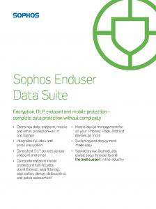
The mean visual separations are presented in Table 1, with standard deviations parenthesized. In the table, ~ denotes marginal significance in a technique’s difference from the other techniques (.10 level of significance), * denotes a difference significant at the .05 level, and ** at the .01 level. The box plots in Figure 5 add to the table’s information, showing the span of the 25th to the 75th percentile (interior of the box), the median (line inside the box), the tails of the distribution (vertical lines) and outliers (circles).
leading to a single output, whereas Grades has several relatively independent dataflow paths. In the previous study, no fault localization technique was present. Also, the participants were not allowed to change any formulas; they could only change the values of the input cells and communicate testing decisions using √ and X marks. These restrictions were important for control and measurement purposes of the current experiment, because it meant all spreadsheets contained the same faults throughout. Eventually it will be important, however, to run interactive experiments with end users actually present to take into consideration how the techniques influence the testing decisions users make.
A negative visual separation is in the correct direction (faulty cells darker than correct cells); given the correct direction, the larger the absolute value of this separation, the greater the visual difference. Hence, being close to the bottom of the Visual Separation axes in the box plots is best. From now on, we will simply refer to larger differences in the correct direction as “better.”
During the course of this previous study, we recorded the testing actions of each participant into an electronic transcript. For the current study, we ran these recorded testing actions through a tool that replays testing actions to extract the test values the users actually entered and checked off or X’d out. These test suites obtained from the electronic transcripts were the test-suite subjects of our current experiment.
We used the Friedman test to statistically analyze the results pertaining to each research question. This test is an alternative to the repeated measures ANOVA, when the assumption of normality or equality is not met. For the first X mark placed in the Change spreadsheet, statistical analysis using the Friedman test showed the Blocking Technique to have a better visual separation than the other two experimental techniques, with marginal significance (df=2, p=0.0561). In the Grades spreadsheet, the Nearest Consumers Technique had a significantly better visual separation (df=2, p=0.0028) than the other two techniques. We therefore reject H1.
6 Results 6.1 Effectiveness Comparisons The effectiveness of a fault localization visualization technique rests on its ability to correctly and visually differentiate the correct cells in a spreadsheet from those cells that contain faults. The better job a technique does in visually distinguishing a spreadsheet’s faulty cells from its correct cells, the more effective the technique. Thus, we will measure effectiveness by measuring the visual separation between the faulty cells and the correct cells of each spreadsheet, which is the result of subtracting the average fault likelihood of the faulty cells from the average fault likelihood of the correct cells. Subtraction is used instead of calculating a ratio because the color choices form an ordinal, not a ratio, scale.
Note that the First-X results for the Change spreadsheet had most of its separations in the wrong direction—the correct cells tended to be colored darker than the faulty ones—but this did not happen in the Grades spreadsheet. Recall that the Change spreadsheet’s cells lined up in a single dataflow chain feeding into the final answer, whereas the Grades spreadsheet had multiple dataflow chains. This may suggest that the techniques are all at a disadvantage in providing reasonable early feedback given a single dataflow chain. The question of whether certain dataflow patterns are especially resistant to early feedback about faulty cells is an interesting one, but it requires further experimentation with additional spreadsheets.
We measured visual separation at two points in time: at the end of testing after all information has been gathered, and very early, just after the first failure is observed (regardless of whether successes have occurred). The reason for measuring visual separation at the end of testing is obvious. The reason for measuring after the first failure (X mark) is because it is at this point that a technique would first give a user visual feedback. This initial visual feedback may be flawed because the technique has very little information upon which to base its estimations; however, this initial feedback is important because it may influence the subsequent actions of the user.
By the last test, the Test-Count Technique showed the benefits of the information that it builds up over time. More tests did not help the Blocking and Nearest Consumer Techniques as much. In fact, by the last test, the Nearest Consumers Technique had significantly worse separations than the Test-Count Technique in both spreadsheets (Change: df=2, p=0.0268; Grades: df=2, p=0.0109), and was not significantly different from the Blocking Technique. Given these differences, H2 must also be rejected.
As a statistical vehicle to shed light on effectiveness, we state the following (null) hypotheses:
We caution that the standard deviations in the data are quite large. These large standard deviations may not be surprising, however,
H1: At the point the first failure is recorded, there is no significant difference in effectiveness among the three fault localization visualization techniques.
Table 1. Mean visual separations, all subjects. First X Last Test TC B NC TC B Change .212 -.008~ .201 -.466* -.227 (n=44) (.798) (.612) (1.213) (.812) (.593) Grades -.016 -.093 -.190** -.151* -.031 (n=43) (.879) (.738) (1.213) (.756) (.597)
H2: By the time all tests have been completed, there is no significant difference in effectiveness among the three fault localization visualization techniques.
129
NC -.152 (.868) .081 (.874)
Table 2. Is the darkest cell faulty at the end of testing? True Identifications False Identifications TC B NC TC B NC Change 18.18% 13.64% 31.82% 11.36% 13.64% 9.09% Grades 44.19% 51.16% 39.53% 6.98% 11.63% 16.28%
Table 3. Mean visual separations, “perfect” subjects. First X Last Test TC B NC TC B NC Change .089 -.078 .078 -.667 -.389 -.456 (n=15) (.877) (.678) (1.367) (.893) (.760) (.856) Grades -.296 -.333 -.722 * -.037 0 .148 (n=9) (.735) (.493) (.833) (.740) (.577) (.626)
given the variations in human behavior during interactive testing. Still, we must be cautious about generalizing from these data.
To consider this issue, of the 44 subjects for the Change spreadsheet, we isolated 29 that contained either a wrong X or a wrong √ mark. Similarly, 21 of the 43 subjects for the Grades spreadsheet contained an erroneous mark. We refer to subjects with no erroneous marks as “perfect,” and refer to the others as “imperfect.” Given this information, we form the following (null) hypotheses to investigate robustness.
The large standard deviations suggest another view of the effectiveness of our visualizations: for how many subjects did the visualization succeed and fail? That is, how often was the darkest cell—colored dark to draw the user’s attention—truly faulty? At the left of Table 2 is the percent of test suites (subjects) in which the darkest cell at the end of all testing was indeed faulty. The right side shows the percent of subjects in which a correct cell was erroneously colored darker than the faulty ones. (Ties, in which the darkest correct cell and faulty cell are the same color, are omitted from this table.) The low false identification rates may be particularly important to end users, who may be relying on the visualizations for guidance in finding the faults.
H3: At the point the first failure is recorded, there is no significant difference in effectiveness among the three fault localization visualization techniques for “perfect” subjects. H4: By the time all tests have been completed, there is no significant difference in effectiveness among the three fault localization visualization techniques for “perfect” subjects.
6.2 Robustness End users engaging in interactive testing are likely to make some mistakes. (Professional programmers would also make mistakes if testing interactively, but in professional software development testing is often treated as more of an asset, with test suites carefully maintained and run in batch.) For example, a user might pronounce a test successful when in fact it reveals a failure. A fault localization visualization technique may not be useful, regardless of its effectiveness, if it cannot withstand mistakes.
H5: By the time all tests have been completed, there is no significant difference in effectiveness among the three fault localization visualization techniques for “imperfect” subjects. Table 3 contains the data for the perfect subjects. Recall that all four of the situations compared in Section 6.1 showed at least borderline significant differences among the techniques. In con-
Figure 5. The box plots for the Change and Grades spreadsheets when all subjects are considered. Of particular interest are the large variances in the data for the Nearest Consumers Technique, and the small variances for the Blocking Technique.
130
trast to this, when restricted to only the perfect subjects, the differences were only significant for the first test of Grades. (First X Change: df=2, p=.6592; last test Change: df=2, p=.3618; first X Grades: df=2, p=.0169; last test Grades: df=2, p=.2359). Although this may be due simply to the smaller sample sizes involved, another possibility is that the errors included in the full sample were part of what distinguished the techniques from one another. We reject H3, but not H4.
sons with the others’ data, and in the large variances within its results. Further, in some cases it performed quite badly by the last test. However, it sometimes performed quite well, especially in the “First X” comparisons. This may say that, despite the fact that it is less consistent than the Blocking Technique, it may still be viable to use during the early feedback period, and its lower expense may make it the most cost-effective choice for this purpose.
Comparing data on the imperfect subjects in isolation is a way to investigate this possibility. We cannot do a “First X” comparison for these subjects, since the sample necessarily includes both subjects with a correct first X followed by other errors, and subjects with an incorrect first X. However, the data for the last test are shown in Table 4.
7 Conclusions and Future Work We have devised three visual fault localization techniques for end-user programmers. Two of the techniques are new in this paper. All three techniques draw from traditional approaches to fault localization, but their incremental algorithms and visualization strategies are unique to the requirements of end-user programming. In particular, all three techniques seamlessly integrate incremental visualizations into the spreadsheet environment.
In the “last test” data for the Change spreadsheet, the Test-Count Technique was best, at a marginal significance level (df=2, p=.0697). For the Grades spreadsheet “last test” data, the TestCount Technique was significantly better than the Nearest Consumer Technique (df=2, p=.0433). Thus, H5 is rejected.
These techniques are still evolving, and thus we conducted an empirical, formative study to direct our efforts toward which one(s) to pursue and in what ways. Some of the more surprising results were:
6.3 Cost-Effectiveness Implications
• Robustness: The ability to withstand user errors was quite different among the three techniques. Test-Count was the most robust in the presence of mistakes. We believe this resilience is tied to Test-Count’s accumulation of historical information. • Consistency: Consistency of results on different spreadsheets and with different test suites was a way in which the techniques differentiated themselves. Blocking had the least variation. • Early feedback: The correctness of feedback at the time of the first X may be critical in encouraging end users to continue testing, marking cells accordingly. Test-Count was not effective at this point. Interestingly, the low-cost Nearest Consumers Technique often did extremely well here.
Whenever the Friedman tests revealed a significant difference by the last test, Test-Count was always the most effective. It was also fairly reliable, reporting a reasonably low number of false identifications, although it did not distinguish itself in true identifications. Further, it seems to be the most robust, maintaining the best visual separations even in the presence of errors. These positive attributes are despite the fact that it is not as expensive as the Blocking Technique. However, it was the least effective of the three techniques at providing early feedback. The Blocking Technique is the most expensive. Despite this, we had expected its effectiveness to be commensurately high, producing a good cost-effectiveness ratio. The previous section’s statistics, however, do not lead to this conclusion by the end of a test suite.
Taking the findings of this study into account, we are considering a number of refinements to our techniques. The robustness of the Nearest Consumers Technique may be improved by incorporating simple counters to record the number of correct and incorrect marks placed on a cell. Furthermore, we plan to manipulate the mathematics of our techniques as an independent variable to learn the extent to which it impacts the performance of the techniques.
The Blocking Technique did show two important advantages, however. First, it was always better than Test-Count for the early feedback. Second, it was much more consistent than the other two techniques, showing smaller spans and smaller variances than the other two in most cases. These facts suggest that if effectiveness were the only goal, a possibility might be to start with the Blocking Technique for early feedback, and switch to the Test-Count Technique in the long run.
The ties with the end-user programmers themselves are our next research focus. For example, the incremental reward that users receive after each mark could have a critical impact on their debugging strategies. Their ability to understand and predict the incremental changes in our visualizations also need to be investigated. We are currently planning empirical work to investigate these and similar issues.
We devised the Nearest Consumers Technique with the hope that it would approach the performance of the other two with less cost. Instead, we learned that the Nearest Consumers Technique was less consistent than the other two techniques, both in the compari-
Other software visualization research is concerned with human factors, but the extent to which our approach depends on these factors is magnified, since our audience consists of end users untrained in fault localization. Supporting this particular audience—which necessitates the highly interactive, incremental approaches presented in this paper—is the essential difference between our work and other software visualization research.
Table 4. Mean visual separations, “imperfect” subjects. First X Last Test TC B NC TC B NC Change -.362 ~ -.144 .006 (n=29) (.763) (.479) (.847) Not applicable Grades -.181 * -.039 .064 (n=34) (.768) (.610) (.936)
131
KIMELMAN, D., ROSENBURG, B., AND ROTH, T. Visualization of dynamics in real world software systems. Software Visualization: Programming as a Multimedia Experience (J. Stasko, J. Domingue, M. Brown, and B. Price, eds.), MIT Press, Cambridge, MA, 1998, 293-314.
Acknowledgments We thank the Visual Programming Research Group at Oregon State University for their feedback and help. This work was supported in part by NSF under ITR-0082265.
LASKI, J. AND KOREL, B. A data flow oriented program testing strategy. IEEE Trans. Soft. Eng. 9, 3, May 1993, 347-354.
References ATWOOD, J., BURNETT, M., WALPOLE, R., WILCOX, E., AND YANG, S. Steering programs via time travel. 1996 IEEE Symp. Visual Languages, Boulder, Colorado, Sep. 3-6, 1996, 4-11.
LIEBERMAN, H. AND FRY, C. ZStep 95: A reversible, animated source code stepper. Software Visualization: Programming as a Multimedia Experience (J. Stasko, J. Domingue, M. Brown, and B. Price, eds.), MIT Press, Cambridge, MA, 1998, 277-292.
BOEHM, B.W., ABTS, C., BROWN, A.W., CHULANI, S., CLARK, B.K., HOROWITZ, E., MADACHY, R., REIFER, D., AND STEECE, B. Software cost estimation with COCOMO II. Prentice Hall PTR, Upper Saddle River, NJ, 2000.
NOTKIN, D., ELLISON, R., KAISER, G., KANT, E., HABERMANN, A., AMBRIOLA, V., AND MONTANEGERO, C. Special issue on the GANDALF project. J. Systems and Software 5, 2, May 1985.
BURNETT, M., ATWOOD, J., DJANG, R., GOTTFRIED, H., REICHWEIN, J., AND YANG, S. Forms/3: A first-order visual language to explore the boundaries of the spreadsheet paradigm. J. Functional Programming 11, 2, Mar. 2001, 155-206.
NTAFOS, S.C. On required element testing. IEEE Trans. Soft. Eng. 10, 6, Nov. 1984. PAN, H., AND SPAFFORD, E. Toward automatic localization of software faults. 10th Pacific Northwest Software Quality Conference, Oct. 1992.
BURNETT, M., AND GOTTFRIED, H. Graphical definitions: Expanding spreadsheet languages through direct manipulation and gestures. ACM Trans. Computer-Human Interaction 5, 1, Mar. 1998, 1-33.
PANKO, R. What we know about spreadsheet errors. J. End User Computing, Spring 1998.
CHEN, T.Y., AND CHEUNG, Y.Y. On program dicing. Software Maintenance: Research and Practice 9, 1, 1997, 33–46.
RAPPS, S., AND WEYUKER, E.J. Selected software test data using data flow information. IEEE Trans. Soft.Eng. 11, 4, Apr. 1985, 367-375.
DUESTERWALD, E., GUPTA, R., AND SOFFA, M.L. Rigorous data flow testing through output influences. 2nd Irvine Software Symp., Mar. 1992.
REICHWEIN, J., ROTHERMEL, G., AND BURNETT, M. Slicing spreadsheets: An integrated methodology for spreadsheet testing and debugging. 2nd Conf. Domain Specific Languages, Oct. 1999, 25-38.
EICK, S. Maintenance of large systems. Software Visualization: Programming as a Multimedia Experience (J. Stasko, J. Domingue, M. Brown, and B. Price, eds.), MIT Press, Cambridge, MA, 1998, 315-328.
REISS, S. Graphical program development with PECAN program development systems. Symp. Practical Software Development Environments, Apr. 1984.
FISHER, M., CAO, M., ROTHERMEL, G., COOK, C., AND BURNETT, M. Automated test case generation for spreadsheets. 24th Int. Conf. Software Engineering, May 2002, 241-251.
REISS, S. Visualization for software engineering—programming environments. Software Visualization: Programming as a Multimedia Experience (J. Stasko, J. Domingue, M. Brown, and B. Price, eds.), MIT Press, Cambridge, MA, 1998, 259-276.
FISHER II, M., JIN, D., ROTHERMEL, G., AND BURNETT, M.M. Test reuse in the spreadsheet paradigm. Int. Symp. Software Reliability Engineering, Nov. 2002.
ROTHERMEL, G., LI, L., DUPUIS, C., AND BURNETT, M. What you see is what you test: A methodology for testing form-based visual programs. Int. Conf. Soft. Eng., Apr. 1998, 198-207.
HEATH, M., MALONY, A., AND ROVER, D. Visualization for parallel performance evaluation and optimization. Software Visualization: Programming as a Multimedia Experience (J. Stasko, J. Domingue, M. Brown, and B. Price, eds.), MIT Press, Cambridge, MA, 1998, 347-365.
TEITELBAUM, T. AND REPS, T. The cornell program synthesizer: A syntax-directed programming environment. Comm. ACM 24, 9, Sep. 1981, 563-573.
HEGER, N., CYPHER, A., AND SMITH, D. Cocoa at the visual programming challenge 1997. J. Visual Languages and Computing 9, 2, Apr. 1998, 151-169.
TELCORDIA TECHNOLOGIES, xSlice: A tool for program debugging. xsuds.argreenhouse.com/html-man/coverpage.html, July 1998.
JONES, J.A., HARROLD, M.J., AND STASKO, J. Visualization of test information to assist fault localization. Int. Conf. Software Engineering, May 2002, 467-477.
TIP, F. A survey of program slicing techniques. J. Programming Languages 3, 3, 1995, 121-189.
132