modes of the dual source trolleybus, an optimal control strategy based on Dynamic Programming was designed, which is aimed at reducing grid peaking.
Liwei Zhang i dr.
Strategija upravljanja energijom zasnovana na dinamičkom programiranju za trolejbus s dvojnim izvorom napajanja ISSN 1330-3651 (Print), ISSN 1848-6339 (Online) https://doi.org/10.17559/TV-20170628043048
ENERGY MANAGEMENT STRATEGY BASED ON DYNAMIC PROGRAMMING FOR DUAL SOURCE TROLLEYBUS Liwei Zhang, Yang Yang, Minghe Sun, Hui Liu Original scientific paper The dual source trolleybus of a new model with battery and super capacitor energy storage system was designed. The related parameters of dynamical system were designed on the basis of theory deduction, and the simulation model was re-developed in ADVISOR software. Based on the analysis of work modes of the dual source trolleybus, an optimal control strategy based on Dynamic Programming was designed, which is aimed at reducing grid peaking power of on-line mode and energy consumption of off-line mode. In addition, the rule based control strategy has also been implemented and compared to the optimized control strategy. The results have demonstrated that the optimization techniques based on Dynamic Programming can make full use of the supercapacitors with high power and fast charging/discharging characteristics, and more effectively distribute the power between the power sources, improve the dynamic performance and economic performance of the trolleybus. Keywords: dual source trolleybus; supercapacitors; energy management; optimal control; Dynamic Programming
Strategija upravljanja energijom zasnovana na dinamičkom programiranju za trolejbus s dvojnim izvorom napajanja Izvorni znanstveni članak Dizajniran je novi model trolejbusa s dvojnim izvorom napajanja s akumulatorom i super električnim kondenzatorom, a s tim povezani parametri dinamičkog sustava dizajnirani su na temelju teorije dedukcije. Simulacijski model razvijen je u ADVISOR softveru. Zasnovana na analizi radnih modova trolejbusa s dvojnim sustavom napajanja, dizajnirana je optimalna strategija upravljanja na temelju dinamičkog programiranja čiji je cilj reduciranje vršne snage mreže on-line moda i potrošnje energije off-line moda. Uz to, upravljačka strategija zasnovana na tom pravilu također je implementirana i uspoređena s poboljšanom strategijom upravljanja. Rezultati su pokazali da metode optimizacije temeljene na dinamičkom programiranju mogu u potpunosti iskoristiti super električni kondenzator velike snage, s brzim punjenjem i pražnjenjem, i učinkovitije rasporediti energiju među izvorima energije te poboljšati dinamičke i ekonomske karakteristike trolejbusa. Ključne riječi: trolejbus s dvojnim izvorom napajanja; super električni kondenzator; upravljanje energijom; optimalno upravljanje; dinamičko programiranje
1
Introduction
In recent years, with the strong support of the government, urban public transport has developed rapidly. However, with the urban environmental pollution, energy shortages and other issues further intensified, the traditional fuel power bus has been unable to meet the needs of energy-saving emission reduction, so the state began to vigorously promote the new energy bus [1]. Nowadays, with the development of rechargeable battery technology and energy-saving environmental protection policy, dual-source trolley bus has been rapidly developed. Dual-source trolley bus’s prominent features are the use of rail and its own power battery installed to generate electricity through dual-source. In the cable network section, the network can generate electricity for the bus and charge the battery at the same time, while in the wireless network section, the bus can rely on the power stored in the battery [2, 3]. Therefore, not only does the dual-source trolleybus solve the problems of traditional trolleybus controlled by the network layout, which has inherent flaws in energy saving and environmental protection, but also those of new energy bus. Trolleybus driving conditions are more complex, especially in the urban environment. Frequent start, acceleration or deceleration often produces a large peak power to the grid causing a lot of load pressure. However, the existing power battery cannot withstand the vehicle acceleration or braking generated by the peak power, and in the regeneration brake process, the battery is also difficult to withstand the brake feedback pulse current, causing the waste of braking energy. Besides, the pulse current will seriously damage the lithium-ion battery and reduce its life [4]. With the rapid Tehnički vjesnik 24, 5(2017), 1439-1447
development of energy storage technology, super capacitor is a new energy storage device with higher power, good safety performance, long cycle life and other outstanding advantages. Therefore, this paper uses lithium battery - super capacitor hybrid energy storage system as the auxiliary power source of trolleybus. Giving full play of lithium batteries and super capacitors in the specific energy and specific power of their respective advantages, can not only reduce the peak power grid and lithium battery power, reduce the charge and discharge frequency of lithium battery, which will extend its life, but can also provide recovery of vehicle braking generated by the regenerative kinetic energy efficiently, thus improving vehicle energy efficiency [5]. There are two kinds of power sources in the dualsource trolleybus: online operating mode and off-line operating mode. To make the two power sources coordinated, a reasonable vehicle energy management strategy is required to coordinate the distribution of power requirements between the different power sources. At present, more control strategies are based on the rule based control algorithm. According to the engineering experience and experiment, the working area of the working parts and the control rules of the vehicle are determined [6]. This control method relies on the accuracy of the rules can’t make the performance of the vehicle to the best. Dynamic programming method is a global optimization algorithm, which is suitable for the optimal control problem under multi-constrained and nonlinear conditions. It has the characteristics of theory completeness, applicability and easy engineering, which has become a hotspot in recent years [7, 8]. Based on the model of vehicle simulation, this paper aims to reduce the 1439
Energy management strategy based on dynamic programming for dual source trolleybus
peak power and vehicle energy consumption of the power grid. The dynamic programming method is used to obtain the energy management strategy under specific working conditions, and it is optimized and compared with the traditional control strategy by means of simulation comparison analysis. Table 1 Parameters of dual source trolleybus
Parameter Full load quality Windward area Maximum speed Rolling resistance coefficient Air resistance coefficient Wheel radius
2
Unit t m2 km/h m
Value 16 7 55 0.012 0.65 0.501
Dual source trolleybus structure and parameter matching
Dual-source trolleybus is powered by the grid and auxiliary energy storage devices, the power system structure and the parameters of the components have to meet the need of vehicle's dynamic performance and the standard of driving range. According to the design Substation
Liwei Zhang et al.
requirements, the selected dual parameters are shown in Tab. 1.
source
trolleybus
2.1 System structure The hybrid energy storage device, which is composed of super capacitor and lithium battery, serves as trolley bus auxiliary power source is shown in Fig. 1. Power system is consists of grid, lithium battery, super capacitor, DC/DC converter, inverter, motor and mechanical transmission system. The power source of the vehicle is the power grid, battery and super capacitor. The power supply is provided by the pantograph for the vehicle. The rated voltage of the power supply in Beijing is DC 650V. The lithium battery is directly connected to the DC bus and can be charged through the grid. The super capacitor is connected to the DC bus through a bidirectional DC/DC converter. When the tram is traveling on a section without overhead contact, the energy is supplied by the energy storage system. The inverter converts the regulated DC voltage into an AC voltage to drive the AC motor. The drive system is used to change the speed ratio and adjust the speed of the output to the wheel. Inverter Wheel
Battery
M
Braking resistor
AC power supply
Rectifie r bridge
Bidirectional DC/DC converter
Mechanical transmission
Electric drive system
S
Super capacitor
Figure 1 The structure of dual source trolleybus
2.2 Motor parameters In the process of trolley bus operating, the response power of the vehicle's demand power is supplied by driving the motor. Therefore, it is necessary to determine the power of the motor according to the vehicle parameters and the dynamic requirements first. The rated power of the motor shall be greater than the demand power of the vehicle at the maximum speed which is:
Pm ≥
1
ηT
(cr mv gvmax +
1 3 rvmax ACd ) . 2
(1)
Where Pm is the motor rated power, cr is the rolling resistance coefficient, mv is the vehicle mass, g is the gravitational acceleration, ρ is the air density, vmax is the maximum vehicle speed, A is the windward area of the vehicle, Cd is the air resistance coefficient, ηT is powertrain efficiency. 1440
The peak power of the motor should be greater than the required power for the maximum acceleration of the vehicle, which is:
Pm ≥
1
ηT
(mv a max v + cr mv gv +
1 3 rv ACd ) . 2
(2)
Where, Pm_max is the motor peak power, amax is the maximum acceleration of the vehicle. The motor speed nm and torque Te are calculated as follows:
vi g nm = (0 ,377 r ) . P 9550 Te = nm
(3)
Technical Gazette 24, 5(2017), 1439-1447
Liwei Zhang i dr.
Strategija upravljanja energijom zasnovana na dinamičkom programiranju za trolejbus s dvojnim izvorom napajanja
Where ig is the transmission ratio, r is the wheel radius. The existing bus transmission ratio is 4.33, 4.875, 5.134, 5.57 and so on. The minimum transmission ratio ig_min should meet the requirements of the maximum speed of the trolleybus, calculated and combined with the actual situation of permanent magnet synchronous motor to Maximum power (kW) 187
Rated power (kW) 100
determine the rated speed of the drive motor 2000 r/min, and the maximum speed 6000 r/min. Based on the above analysis, this paper chooses MC_AC187 motor in ADVISOR simulation software to meet the vehicle power demand. The specific parameters are shown in Tab. 2.
Table 2 Parameters of MC_AC187 motor
Maximum torque (N·m) 850
2.3 Capacity optimization of energy storage system The parameter design of the energy storage system is a compromise optimization process, that is, in addition to meet the basic energy and power requirements of the vehicle,we should also minimize the input cost [9-12]. As for the dual source trolleybus, the access line running can be achieved by online charging, therefore the vehicle travel distance and off-line travel distance directly affect the energy storage system capacity configuration. Combined with the characteristics of lithium batteries and super capacitors, lithium batteries preforms as the main energy source meet the vehicle capacity requirements, while super battery as a secondary energy source meets the power needs of vehicles. Therefore, this paper not only uses the idea of main and auxiliary energy source capacity and power independent design, but also considers the off-line comparison of the running route of trolleybus to design the parameters of hybrid energy storage system. Tab. 3 is the Parameters of the selected battery and super capacitor.
Rated torque (N·m) 530
Model (V) Rated voltage (Wh/kg) Power density (kW/kg) Monomer quality (kg) Monomer price (yuan)
Lithium battery Super capacitor Saft_LSH14 Maxwell_PC2500 3.6 2.5 116 6 0.4 12 0.275 0.51 120 324
At an average speed va = 30 km/h, the average energy consumption per kilometre of the trolleybus Qa is:
Qa =
Pa 1 1 (cr mv g + rva2 ACd ) = 1,5 kW ⋅ h/km . = va h T 2
Rated rotating speed (r/min) 2000
Where L is the full distance travelled, D is the off-line travel distance. In order to achieve the maximum use of wire network, in addition to charging during the grid section, there is no need to spend additional parking time to charge the lithium battery. So the energy consumed in the off-line section should be compensated in the cable section. Running time for a single bus is generally 2 hours, when it is considered that the maximum cycle is 7 times a day, that the balance of the lithium battery is 30%, and that a single cycle of energy difference is 10%, there is formula:
X + 0.1 ≥
D . Dmax
(7)
It can be drawn that the condition lithium battery capacity should meet is as follow: Ebatt ≥
Table 3 Parameters of battery and super capacitor
Parameter
Maximum rotating speed (r/min) 6000
90 D . L−D+6
(8)
Taking the off-line ratio k = D/L, there is:
E batt ≥
90k . 1− k + 6 L
(9)
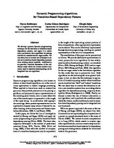
Fig. 2 is a three-dimensional relationship diagram which shows the relationship among off-line ratio k, travel distance L and lithium battery minimum capacity Emin, we can see that the greater the off-line ratio, the greater the required lithium battery capacity.
(4)
Set the lithium battery capacity as Ebatt, if the lithium battery is fully charged, the maximum off-line mileage Dmax on theory of the vehicle is:
Dmax =
Ebatt 2 = Ebatt . Qa 3
(5)
The charging rate of lithium battery by network is 0.5C, the vehicle at an average driving speed under the charge energy percentage X is:
L−D × 60 L−D X = 30 = . 120 60 Tehnički vjesnik 24, 5(2017), 1439-1447
(6)
Figure 2 The dimensional diagram of k, L and Emin
Taking the 103 trolleybus in Beijing as an example, the full travel distance L = 26.7 km, off-line distance D = 6.9 km, off-line ratio k = 0.26, the minimum capacity of 1441
Energy management strategy based on dynamic programming for dual source trolleybus
lithium battery is 23.9 kW·h, so the amount of lithium battery monomer is at least n1 = 23.9/0.032 = 746.8. Taking the method of lithium battery connection into account,we use 125 monomer in series, the rated voltage is Ub_nom = 125 × 3.6 V = 450 V, and then take 3 series in parallel, thus n1 = 750. Super capacitor has to meet the requirements of energy and power when it comes to the conditions that the vehicle has the maximum acceleration. According to the motor peak power derived above, the super capacitor power has to meet: Psc ≥
Pm_max
ηm
(10)
= 208 kW .
Among them, ηm is the motor efficiency. Super capacitor energy to meet the vehicle t = 10 s peak power, is: Esc ≥
Pm_max
hm
(11)
⋅ t = 0.58 kW ⋅ h .
Considering the power and energy requirements, the amount of supercapacitor monomers is n2 = 190. Using a single series connection, the super capacitor group rated voltage Usc_nom = 190 × 2.5 V = 475 V. When considering the power output capacity and energy storage capacity of the energy storage system, the amount and cost of the single unit in the single lithium battery storage mode and the mixed energy storage mode are shown in Tab. 4. Table 4 Cost comparison of different energy storage
Energy storage method Lithium battery Mixed energy storage
Lithium battery amount
Super capacitor amount
Total cost (Million yuan)
1890
0
22.68
750
190
15.16
As can be seen from Tab. 4, due to its low density, when performing as the vehicle energy storage device, lithium battery system costs more than mixed energy system when there is a need to meet the requirement of vehicle power as well as that of storage at the same time. The super capacitor in hybrid energy storage system is responsible for providing high demand for vehicle power. Lithium battery is responsible for meeting the requirements of the vehicle driving range. Therefore, the use of hybrid energy storage system can reduce costs and improve economic efficiency. 3
performance can optimize the aims. The control requirements are: to ensure the full power of the vehicle under the premise of giving full play to the advantages of super capacitor, such as, high energy density, charge and discharge in a fast speed when there is a high current. In the on-line operating mode, reduce the peak power of the grid; in the off-line operating mode, reduce the impact of high current on the battery, improve the charge and discharge efficiency, extend the battery life, maximize the recovery of braking energy and improve vehicle economy. The global optimization management strategy is a multi-source system energy allocation strategy developed by the application optimization method and the optimal control theory. The strategy includes linear programming method, nonlinear programming method, dynamic programming method, Multi-target tracking algorithm and genetic algorithm. Genetic algorithm is a computational model for simulating the natural selection and genetic mechanism of Darwin's theory of biological evolution. It is a method to search the optimal solution by simulating the natural evolutionary process. Arango et al. proposed a mathematical model and developed a heuristic procedure based on a genetic algorithm to solve non-linear problems. Nishimura et al. developed a heuristic procedure based on a genetic algorithm to obtain a good solution with considerably small computational effort. This algorithm can also be used to solve the problem of production coordination [13, 14]. Multi-target tracking algorithm is based on depth learning. First, the GoogLeNet + LSTM model is used for target detection to obtain accurate target detection results. On the basis of this, a method of extracting the depth feature directly from the feature map based on the target detection method is proposed. The traditional feature of the depth feature can reflect the appearance of the detection target more accurately than the traditional feature such as scale invariant feature transform (SIFT), so it can improve the accuracy of the target tracking algorithm [15]. 3.1 Analysis of operation mode of dual - source trolleybus According to the difference among power supply for energy work of dual-source trolleybus, the operating mode of dual-source trolley bus is divided into on-line operating mode and off-line operating mode, as is shown in Fig. 3. On-line operating Off-line operating On-line operating
Energy management strategy based on dynamic programming
The energy management strategy is an indispensable part of efficient operation of dual-source trolleybus. It allocates the power between the grid and the energy storage equipment according to the power demand of the vehicle under different road conditions, so that the vehicle 1442
Liwei Zhang et al.
Figure 3 The operating mode of dual source trolleybus
Fig. 4 shows that the power flow of the trolleybus is in the on-line operating mode. At this time, the trolleybus Technical Gazette 24, 5(2017), 1439-1447
Liwei Zhang i dr.
Strategija upravljanja energijom zasnovana na dinamičkom programiranju za trolejbus s dvojnim izvorom napajanja
is connected with the catenary, the vehicle is powered by the power grid and the super capacitor. The super capacitor is connected with the DC bus through the bidirectional DC/DC converter, power relationship is shown in Eq. (12). Among them, Preq is the demand power of the vehicle, Pgrid is the power of grid, Psc is the power of the super capacitor. When the vehicle is running in the traction mode, the grid provides steady power required for normal driving. When the vehicle accelerates, the super capacitor provides the different power of the power grid and the demand power, and reduces the average power of the grid output. When the vehicle decelerates while braking, the super capacitor charging, recycling regenerative braking energy. In addition, if the battery charge state is lower than the off-line driving demand, the grid needs to charge the battery to ensure the energy needs of off-line operating mode. Preq (t ) = Pgrid (t ) + Psc .
(12)
the field of operational research. It is a numerical algorithm based on Bellman's optimization principle for solving multi-stage decision problems [16, 17]. The multi-stage decision problem is divided into N stages by time. At each stage, it is necessary to make a decision, and the decision variable uk of the given stage is determined. The state variable xk of the k + 1 stage xk+1 is also determined, the k stage to k + 1 stage of the state transfer law is called state transition equation, expressed as:
xk +1 = f k ( xk , u k ) where k = 0, 1, ..., N−1. The control vector of the system is:
u = {u 0 , u1 , ...., u N −1} u k ∈ U k .
In off-line operating mode, the lithium battery is the main energy source, the super capacitor is the auxiliary energy source, and the power flow is shown in Fig. 5. The power flow is the same as that of the pure electric vehicle. The power relationship is shown in Eq. (13), where Pbatt is the power of battery. When the vehicle is running in the traction mode, the power battery and the super capacitor cooperate to provide energy for driving the motor; when the vehicle decelerates while braking, the motor is in the power generation state, the regenerative braking energy is given to the super capacitor through the DC/DC converter, the excess part of the energy is used to charge the lithium battery.
Preq (t ) = Pbatt (t ) + Psc (t ) .
(13)
N −1
∑ L( xk , u k ) .
(16)
k =0
Among them, L(xk, uk) is the state between xk and xk+1, and the optimal value function obtained by optimizing the calculation is the function that minimizes the total value, and the corresponding control vector is the best control vector. The central idea of the Bellman principle is that if the optimal solution path of the problem passes through an intermediate state, then the optimal solution from the state to the end of the process is the continuation of the optimal solution path of the whole process [18].
B 5 2 4 4 8 C4 5 A 7 6 5 3 D8
E 4 9 F6 8 8
H 6
6 9
G6 a)
B 20 A
3.2 The principle of dynamic programming Dynamic programming method is one of the tools to solve the global optimization problem, which belongs to Tehnički vjesnik 24, 5(2017), 1439-1447
16
25 C17
23 Figure 5 Power flow of off-line operating mode
(15)
The goal of dynamic programming is to find the best control strategy so that the sum of the objective function values at each stage is minimized. The value function starting with state x0 is as follow:
J u ( x0 ) =
Figure 4 Power flow of on-line operating mode
(14)
I8
K
8 J
E 13
H
F
I8
14
9 K
8
17 D
9
G 14
J
b)
Figure 6 Shortest path optimization problem
Fig. 6 is the diagram of shortest path optimization problem, which calculates the shortest path from point A to point K, the number of stages is N = 5, the figure 1443
Energy management strategy based on dynamic programming for dual source trolleybus
between the two lines of the edge of the line is the distance from the previous point to the next point. If the state points of the process are not too many, it is very easy to find the minimum time path by considering all the possible paths, but it is not possible to use this method if there are too many state points. And the use of optimization algorithm can reduce the need of considering the number of paths. The first step in applying the dynamic programming algorithm is to calculate the consumption value of the state changes between two consecutive steps. As shown in Fig. 6(a), all the values between any two states are shown. Once all values between any two states are determined, the minimum value of all state points is reversed to the end point. At stage N = 4, the minimum value of each state point to end point K is the corresponding inter-state value. In the case of N = 3, there are three paths to the end point K for point F, which are F → H → K, F → I → K, F → J → K, and the corresponding distances are 15, 14 and 16, respectively. The best path from the state point F to the state point K is the path of the state point I, with the shortest path length 14. Similarly, the best path for point E to point K is E → H → K, the minimum distance is 13, and the best path from point G to point K is G → J → K, and the minimum distance is 14. After calculating these figures, the algorithm moves to N = 2 to calculate the minimum value of state points B, C, and D. According to the Bellman optimization principle, the optimal path from the state points E, F and G to K is not affected by the previous time step, so the minimum value from B to K is the state from B to E, F and G. The value plus the minimum value from these points to K, for example, the minimum value of path B → E → K is equal to the value of state between B and E plus the minimum value of E to K. In the same way, we can calculate the minimum value of all the state points as shown in Fig. 6(b) and the optimal path with the shortest distance of 20 from A to K. The path passes through the state points B, F and I. 3.3 Dynamic planning process
1444
2.78 × 10 −5 E _ J . L
t
∫
E _ J = ( Pbatt + Psc )dt .
(17)
(18)
0
Where ECR is the vehicle energy consumption per 100 km; E_J is the energy consumed in the vehicle travelling process; L is the travel distance of the vehicle, 2.78 × 10⁻⁵ is the unit conversion factor. The SOCsc of the super capacitor is the state variable in both modes, and the control variable is the electric power Psc of the super capacitor, as shown in the following equation:
x = {SOCsc (t ) }, u = {Psc }.
(19)
The relationship between the system state variable and the control variable is: t
SOC sc (t ) = SOC0 +
∫ Psc (t )dt 0
Esc
.
(20)
Where Esc is the maximum capacity of the super capacitor, and the charge state transition equation is obtained by deriving and discretizing both sides of the above equation:
SOC k +1 = SOC k +
Psc ⋅ ts , k = 1,..., N t − 1. Esc
(21)
Where ts is the sampling time and Nt is the number of sampling points. For the system state variable SOCsc, it can be discretized into Ns values between the maximum and minimum values, as shown in the following equation: SOCi = SOC min + (i − 1)
The goal of energy management of dual-source trolleybus is to realize the reasonable allocation of power between the energy sources. This process is discretized by time and can be regarded as a multi-stage decision problem. The dynamic programming method can be used [19, 20]. When the dual-source trolleybus is in on-line operating mode, the power is supplied from the grid to the vehicle. The super capacitor replenishes the peak power and recovers the braking energy. The dynamic programming method is used to optimize the power distribution between the grid and the super capacitor. The goal is to reduce the peak of the grid power Pgrid max; in the off-line operating mode, the dynamic programming method is used to reasonably allocate the power between the battery and the super capacitor, the evaluation index is the vehicle energy consumption ECR, the formula is as follows.
ECR =
Liwei Zhang et al.
SOC max − SOC min , i = 1,..., N s . (22) Ns −1
For the battery and the super capacitor, in order to extend their service life, their SOC should work within a certain allowable range during working process, namely:
SOC batt min (t ) ≤ SOC batt (t ) ≤ SOC batt max (t ). SOCsc min (t ) ≤ SOCsc (t ) ≤ SOCsc max (t ).
(23) (24)
If the SOC value is too high, the trolleybus is hard to recover renewable energy, which will produce energy waste; on the other hand, if the SOC value is too low for a long time, it will greatly reduce the battery life, and affect the vehicle acceleration performance. In actual operation, we set the SOC of the battery and super capacitor in the range of [0.3, 0.9]. 3.4 Dynamic Programming reverse order method Based on the Bellman principle, we can see that if the intermediate state to the end state of the optimal path of the whole process is regarded as a subroutine, then the Technical Gazette 24, 5(2017), 1439-1447
Liwei Zhang i dr.
Strategija upravljanja energijom zasnovana na dinamičkom programiranju za trolejbus s dvojnim izvorom napajanja
optimal path of the subroutine is the latter part of the optimal process of the whole process. The dynamic programming algorithm is an optimization method of reverse calculation. The recursive equation of the reverse order method is:
(
)
J k ( SOCi ) = min Lk ( xk , u k ) + J k +1 ( SOC j ) , J Nt ( SOC Nt ) = 0.
maximum output power of the grid is 27.2 kW, and the maximum output power of the power grid is 21.7 kW under the dynamic programming method.
(25)
Where Jk(SOC) represents the minimum value consumed from time k to the final time along the optimal path, and Lk(xk, uk) is the value consumed by state xk to xk+1. Fig. 7 is the flow chart of dynamic programming reverse order method, roughly divided into the following three steps: 1) Initialize, the vehicle driving process is divided into N stages, and from the Nth stage to calculate the minimum value from this stage to the final state; (2) For the kth stage, the optimal decision of the kth stage is obtained for the value of Eq. (15) uj under the state variable xi of this stage. (3) If k = 1, then go to (4), otherwise, k = k − 1, go to (2); (4) When k = 1, the optimal decision of the whole cycle is obtained.
Figure 8 Rule based control simulation waveform of on-line operating mode
Initialization
For k=N:1
no
no
For x=xmin:xmax
j=1
While uj