Engineering of Validatable Automation Systems Based on an Extension of UML Combined With Function Blocks of IEC 61499 Viktor Dubinin Penza State University, Russia e-mail:
[email protected]
Abstract - This paper suggests a comprehensive engineering framework for software design for component-based distributed industrial automation based on the combination of UML with the function block concept of the newly emerging international standard IEC61499. Four UML diagram types have been used, namely: class, sequence, cooperation and state-chart diagrams. The UML design is transformed then to the executable function block specification following the IEC61499.
I.
INTRODUCTION
The main focus that is currently observed in the development of automation systems is in the transition to distributed intelligent systems based on network technologies. This process goes hand in hand with the recognition of the growing importance (and complexity) of software and correspondingly software engineering in automation. Both these trends resulted in the development of new international standard IEC61499 [1]. According to the IEC61499 reference architecture a control system consists of one of several independent physical devices communicating via a network media. The functions of the system are determined by an application that can be allocated to a single device or can be distributed over several devices of the system. The application is defined as a network of function blocks (FB) interconnected via event and data links. A device is defined as a collection of resources, each of them is a unit structure having independent control of its operations and providing certain services to the applications that may include scheduling and execution of algorithms. Examples of automation system design using the function block concept of IEC61499 can be found in [2,3]. Thus, in [2] several patterns are suggested, among which the object-oriented pattern Model/View/Controller (MVC), the Distributed Application Pattern, the Proxy pattern, etc. In [3] the MVC pattern is applied to automation of a model of modular production system based on mechatronic components of FESTO Didactic GmbH (Germany). The IEC61499 standard supports the function block based engineering paradigm. This concept accumulates the experience of industrial automation practice and combines it with modern concepts of component-based software engineering. System
Valeriy Vyatkin Thomas Pfeiffer Martin Luther University of Halle-Wittenberg, Germany e-mail:
[email protected],
[email protected]
description in terms of FB is a kind of executable specification. For example, the control system exemplified in [3] executes the function blocks on a Netmaster control device (a make of Italian company Elsist), that is built using the embedded Java™ microprocessors TINI of Dallas Semiconductors (USA) in the Series I and SNAP of Imsys (Sweden) in the Series II. However, despite its numerous advantages, the function block concept of IEC61499 does not use all the potential benefits of the object-orient and component-based software engineering. The object-oriented approach to software engineering is one of the most promising in the industry. First works on application of this approach in industrial automation and control systems date back to early 90-s. One of the dominating trends in them is the use of Unified Modeling Language (UML) [5] in general, and of its extensions, such as UML-RT [6] dedicated for complex embedded and realtime applications in particular. Another example of UML extension for modeling of control systems is CSML [7]. In some works the UML is combined with some other means of system description, e.g. data flow diagrams [8], SDL [9], etc. Along with clear benefits of the object-oriented methodology, the use of UML exhibits also certain problems, among which: 1) A weak orientation of control engineers in advanced software engineering methods. 2) Certain difficulties in implementation of event flows; 3) Difficulties in generation of a fully executable control application from UML; There were certain efforts in the last years to bring together the UML and the FB-based engineering methodologies, in particular in [10, 11, 15]. Thus, in [15] both approaches were compared in details, and the conclusion was made that they are very close to each other though the former is a subset of the latter. The work [10] suggests transformation of certain UML diagrams (use case and sequence diagrams) into networks of function
blocks. These transformations have been used in the software toolset FBDK CORFU. In [11] a profile for adapter interface FBs is suggested that would connect ports of the UML-RT with the FB-oriented languages of IEC61131 [12], IEC61499, and Matlab/Simulink. Besides, a new initiative of IMS (Intelligent Manufacturing Systems International R&D Program [13,14]) targets the integration of automation system developers using open standards, such as IEC61499, IEC61131, and UML. However, despite the stirring up of the works on bringing together the function blocks and UML engineering approaches, they are far from being completed. In particular, the methods of transformations between UML and FB are still not enough developed. As the experience of the authors shows, there is a gap between the engineering paradigms that sets hurdles in implementation of UML specifications using the FBs of IEC61499. One of the reasons of that lays in different approaches for description of program systems and business processes (UML) and block diagrams (FB). The goal of the recently started research project VAIAS Validatable Architectures for Industrial Automation Systems (funded by German Ministry for Education and Research and by the industrial partners) is the development of an architecture that attempts to combine: - an approach to software (and system) engineering following the structure of the original system (object-based engineering), and - inherited validatability, that means facilitated application of formal analysis methods through the architecture. VAIAS intends to meet the new challenges of the automation world providing new software architecture that could better fit to the decentralized reconfigurable nature of automation systems of new generation, will have a higher inherited level of robustness, and will be “friendlier” to formal analysis and synthesis. The basic building blocks of VAIAS will be Automation Objects (AO), which can be basic or composite. Description of a basic block type does not include references to other AO types. The architecture will be based on the standard IEC61499 architecture at the execution level, and will employ some ideas of UML at the design level. In this paper an attempt is made to bring closer the UML with the function block representation that has resulted in a draft proposal of UML-FB language, which is considered as the initial engineering language in the VAIAS architecture. The paper is structured as follows: In Section 1 the language UML-FB is introduced. Section 2 features a case study report on application of the UML-FB for development of distributed control systems of a mechatronic testbed. Section 3 provides the rules for transformation of UML models into function blocks. In conclusion the results and plans for further research works are discussed. II. UML-FB LANGUAGE FOR MODELING AND IMPLEMENTATION OF AUTOMATION SYSTEMS USING THE IEC61499 STANDARD All structures that are representable in function blocks can be represented also in the UML-FB language. Thus, the UML-
FB can be considered as a language for modeling automation systems, and the same time as certain extension of the FB specification of IEC61499 by the UML means. For instance, the UML-FB allows explicit definition of the system’s hierarchy as a class diagram. For specification of the desired behavior the sequence and cooperation diagrams can be used, which are not available in IEC61499. Besides, there is an opportunity to use UML as a specification query language (for validation and testing of the model) and as a structural and functional constrain language (for the synthesis of correct models). The UML-FB extends UML using the mechanism of stereotypes. At the same time the firm rules of diagram application and specific semantic constrain its application in other application domains. The approach introduced in this paper relies on the following assumptions: 1) The function blocks and other structures of IEC61499 are used for describing an “executable specification” of a control system. 2) The UML-FB is used as a language supporting the engineering process: modeling, design and maintenance of the automation system. These assumptions explain why the transition from the UML-FB to FB needs to be very smooth and consistent. Both UML and IEC61499 are using the concept of typing/instantiation not only for data but also for code capsules. We implicitly assume that the class concept of UML corresponds to the function block concept of IEC61499 and vice verse. A. Types of diagrams used The UML-FB uses the following types of diagrams: class diagrams, sequence diagrams, cooperation diagram and state charts. Class diagrams are used for the representation of structure that includes: - the full hierarchy of functional system components (defined by the aggregation and inheritance relations); - the types of function blocks, subapplications, adapter interfaces, resources and devices; - the system, device and resource configurations; - the function block interfaces including event and data inputs and outputs and the corresponding WITH qualifiers; - the connections between function blocks typical for instances of given types; - the constant data representing input parameters of function blocks, subapplications, resources and devices; Sequence and cooperation diagrams are used to support definitions of the application’s dynamics and its transformation to the connections between function blocks, as well as between parameters and corresponding function
blocks, resources and devices. They also can be used for the generation of time-sequence diagrams following ISO TR 8509 which are applied in IEC61499 function block paradigm for description of behavior of Service Interface Function Blocks. Using the cooperation diagrams (extended with text constructs at connections) it is possible to define point to point connections between function blocks. State Chart Diagrams of UML-FB are used to specify exact behavior of components that is determined the Execution Control Charts (ECC) of basic function blocks. In accordance with the ECC structure the state charts of UML-FB are made fairly simple: they do not include composite and historic states, as well as complex transitions. B. Types of connections by localization The class diagrams, sequence diagrams and cooperation diagrams allow the use of various connection types that are specified by the criterion of connection’s localization. An illustration of connection types is given in Figure 1. In the upper part of the Figure1 (a) a tree of object hierarchy is presented and in the right part a system of nested function blocks is shown that is generated from the tree. Among the connections we distinguish local and transit ones. The local connections are direct links at the same level of hierarchy (e.g. between sibling objects as the F1 – F4 connection) and direct inter-level connections, such as the link between objects F0 and F1.
definition of interfaces in the classes through which it goes by. For example, an implementation of the transit link between F3 and F5 (that is outlined in Figure 1 by a bold line) requires four links between F3, F2, F1, F4, F5. Each of the blocks F2 and F1 requires a new output and block F4 acquires a new input. The naming of the generated inputs and outputs is done according to the name of the link or to the names of the link roles. C. Class stereotypes The stereotyping of classes in UML-FB is done according to the basic concepts of the IEC61499 standard and to the classification of function blocks presented below. A base of the IEC61499 architecture is the concept of Function Block (FB). The standard distinguishes basic (BFB), composite (CFB) and service interface function blocks (SIFB). Besides, the standard defines subapplication that is different from the composite FB only in processing of inputs and outputs: definition of a subapplication type does not have WITH links between events and data. This means that no specific storage provided for inputs and outputs on the level of the subapplication. The classification of function blocks is presented in Figure 2.
FB
F0:A
F1:B
F2:C
BFB
CFB
F4:E
SIFB F5:G
PSIFB а)
F0:A
F2:C
F4:E
F3:D
CSIFB
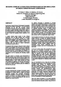
Figure 2. Function block classification.
F3:D
F1:B
TSIFB
F5:G
б)
Figure 1. An example of object hierarchy and the implied structure of nested function blocks. The transit connections are used between objects located on different levels and possibly even in different branches of the hierarchy tree. The IEC61499 does not allow direct use of such connections. To implement a transit connection several interlevel links have to be used. Besides, a transit link implies re-
The FB-Class is located in the root of the hierarchy and defines all other classes. BFB represents basic function block. BFB stands for Basic Function Blocks, CFB for Composite Function Blocks, and SIFB for Service Interface Function Blocks. This classification comes directly from IEC61499. We suggest some specification of the classification of SIFBs based on their functional domain: PSIFB stands for process interface function blocks that provide connection with controlled object (plant), TSIFB are used to implement for interfaces with peripheral equipment, such as timers, and CSIFB for encapsulation of communication functions. Besides, the class diagrams if UML-FB use the following stereotypes of classes with self-explanatory names: SUB for subapplications, ADAPTER, CONSTANT, SERVICE (a service in a SIFBs), SYSTEM, DEVICE, DEVICE_TYPE, RESOURCE,
RESOURCE_TYPE, Interface stereotype.
APPLICATION
and
a
pre-defined
D. Class diagram relations A class diagram of the UML-FB uses relations of aggregation, inheritance, association, and dependency. The system hierarchy of function blocks can be completely defined using the aggregation. It defines not only a complete hierarchy of classes (or FB types) but also determines the hierarchy of objects (in other words, instances of function blocks) that is achieved using aggregative connections roles. Name of the role determines the name of the corresponding function block instance. Thus the number of instances of certain function block type is determined by the number of the corresponding aggregation links. The association relation is used to determine the event, data and adapter connections between FB. An associative link (which can be of type EVENT, DATA or ADAPTER) determines an each-to-each correspondence between the corresponding FB instances. The inheritance relation can be applied to describe inheritance of event, data, and adapter inputs and outputs of function blocks, as well as to describe inheritance of complete interfaces. The dependency relation allows the definition of various semantic relationships between objects, such as “Client-Server”, “Daemon”, “Mechanic link”,” Physical link”, but does not directly influence the code-generation. III. AN EXAMPLE OF UML-FB SPECIFICATION
A commercially available modular processing system of FESTO Didactic (Germany) was taken as a base of the testbed. Each station is controlled by a Netmaster control device (a make of Italian company Elsist) that is a minicontroller with analogue and discrete I/Os and TINI microprocessor – a hardware implementation of the Java virtual machine. For execution of function blocks we used FBRT from Rockwell Automation – that is a Java based run-time platform included in the experimental software toolset supporting IEC61499, which runs both on PC and on Netmasters thanks to the platform independence of Java. The other part of the toolset is Function Block Development Kit (FBDK) – the engineering software tool [17]. A PC was used as an engineering station, as well as for allocation of human-machine interface components and for rendering of the process. PC and Netmaster were connected via Ethernet. As shown in Figure 3, the plant is composed of three stations, namely Distribution Station, Test Station, and Processing Station. The function of the Distribution Station is to draw a workpiece from a magazine and to feed it to the Test station. The Distribution Station is composed of two modules, i.e., the feed magazine module and the transfer module. The function of the Test Station is, to determine the material characteristics of the workpiece, to check the workpiece height, and either to reject the workpiece or to make it available for the subsequent station determined by its material characteristics.
In this Section the ideas of UML-FB based system engineering will be justified by giving an example of a control system development for a testbed that is a model of modular production system presented in Figure 3. The system consists of three production stations that model production process by moving workpieces and performing various operations on them. The processing units are represented by “mechatronic objects” that are capable of performing certain operations, for example measuring of the workpiece height, drilling the workpiece, etc. a)
Figure 3. A model of modular production system. The testbed is installed in Automation Technology Lab of Martin-Luther University of Halle-Wittenberg (Germany) [16].
b)
Figure 4. UML-FB representation of a cylinder (pusher).
The Processing station consists of a rotary table with 4 slots for workpieces, a drill, a device measuring quality of the drilling (checker), and a clamp preventing rotation of the table during the drilling and measurement operations. One may clearly distinguish 4 “mechatronic objects” in this system: table, drill, checker and clamp. In addition, there is a human machine interface panel with several buttons, switches and LEDs. The development of the control system of the testbed was performed following the methodologies of object-oriented and structural design. The latter includes both bottom-up and topdown methodologies. The application of the bottom-up methodology is justified by the existence of mechatronic equipment that can be delivered by its vendor accompanied by some pre-programmed embedded devices and/or software components.
devices of level n and of a control of level n. It is assumed that a virtual device of level n provides services of a higher level than a device of level n-1. Electromechanical devices like sensors and actuators are assumed to be of level 0. Virtual devices of level 1 are designated to be standard event flow devices that play a special role in system engineering. In terms of IEC61499 such devices are represented as SIFBs. Figure 4 features an example of class and sequence diagrams representing a virtual control device of a pusher that is implemented by a pneumatic cylinder. The pusher, represented as a class SGV2 (of level 2), has an event input req_eject “eject the workpiece” and event output cnf_eject for confirmation of the ejection. It is assumed that the vendor of the pusher supplies it with the service interface function block SGV1. Control of the pusher follows the specification presented in Figure 4 (bottom) as a sequence diagram. IV. GENERATION OF FUNCTION BLOCKS FROM UML MODELS
In the presented methodology the design of purely program components can be conducted in accordance with the top-down approach. For instance, to implement a binary semaphore initially a CFB-class Semaphore was developed, that was specified further with BFB classes EI_Var and Arbitr as exemplified in Figure 5, top. The CFB-class Semaphore has the following event inputs: p1,p2,p3 – close requests from clients 1,2,and 3 correspondingly; v – a request to open semaphore; and event outputs e1, e2 and e3 – that are the confirmations of the semaphore’s closure from the clients 1, 2, and 3 correspondingly.
Figure 5. Binary semaphore implementation in UML and in the form of function blocks. The design process consists of the hierarchical composition of virtual logic devices up to the level sufficient to control the whole station. A control device of the (n+1)th level of hierarchy is represented as a pair, consisting of one or more controlled
Figure 6. A composite function block generated from the class diagram in Figure 4. The example in Figure 5 also illustrates the use of different types of relations in the class diagram. Thus, the Semaphore class aggregates three instances Var1, Var2 and Var3 of type EI_Var. A same-level connection “av>w” between the classes Arbitr and EI_Var implies that
the event output av of the block Arbitr will be connected with event outputs of blocks Var1, Var2 and Var3. The inter-level link “v-> v” with an EVENT stereotype between classes Semaphore and Arbitr defines a connection between input v of the capsule and the same name input of the nested function block of the Arbitr type. The Semaphore class inherits the event inputs e1, e2 and e3 from the Arbitr class. Class EI_Var inherits the interface I_EI_Var. Provided that there is a cooperation diagram is defined, a network of function blocks can be generated as the one in Figure 5. Figure 6 illustrates another example of a function block network generated from the diagrams in Figure 4. V. TOOL FRAMEWORK All steps of the suggested engineering process are supported by the corresponding software tools developed in Penza State University as follows: - Converter from UML to IEC 61499 function blocks is intended for transformation of UML-model supported by CASE-tool Rational Rose to XML-representation of IEC 61499 function blocks. A set of function blocks is in accordance to IEC 61499 standard. - Converter from IEC 61499 function blocks to UML is intended for transformation of XML-representation of IEC 61699 function blocks to UML-model supported by CASE-tool Rational Rose. A set of function blocks is in accordance to IEC 61499 standard. Experimental prototypes of tools are available at [18, 19] for download. VI. CONCLUSION The paper presented an approach supporting the automation systems’ engineering that is based on UML and IEC61499. Application of several UML diagrams has been studied that together provide a comprehensive support of the engineering process. The further steps of the work will include extensions of the developed backbone framework in the direction of particular ontologies that would make the engineering more “objectoriented” in the sense of physical mechatronic objects rather than objects in pure software-engineering sense. The goal of such an extension would be to provide a consistent system engineering approach around the engineering of the software part. Another possible extension would be to study the ways of encapsulation of the object’s dynamics with a goal of providing a comprehensive framework for modeling of the closed-loop automation systems. ACKNOWLEDGEMENT The work of V. Vyatkin and T. Pfeiffer was supported in part by the cooperative project VAIAS funded by the German Ministry for Education and Research (BMBF) and industry.
REFERENCES [1]. IEC61499 – Function Blocks for Industrial Process Measurement and Control Systems, International Electric Commission, Draft, Tech.Comm.65, Working group 6, Geneva, 2001 [2]. J.H. Christensen. Design patterns for systems engineering with IEC 61499, Conference “Distributed Automation” (Verteile Automatisierung), Proceedings, Magdeburg, Germany, 2000 [3]. X. Cai, V. Vyatkin, H.-M. Hanisch, Design and implementation of a prototype control system according to IEC 61499, 9th IEEE International Conference on Emerging Technologies and Factory Automation (ETFA2003), Proceedings, Lisbon, Portugal, 2003 [4]. T. Tomilla, O.Venta, K. Koskinen. Next generation industrial automation – needs and opportunities // Automation Technology Review, 2001, p.34-41 [5]. Gomma, H. Designing Concurrent, Distribute, and Real-Time Applications with UML, Addison Wesley 2000 [6]. B.Selic, J.Rumbaugh. Using UML for complex real-time systems, http://www.objecttime.com/technical/umlrt.html [7]. K.Zagar, M.Plesko, M.Sekoranja, G.Tkacik, A.Vodovnik. The control system modeling language, 8 th Int. Conf. On Accelerator&Large Experimental Physics Control Systems, Proc., San Jose, California, 2001, p. 472-474 [8]. M.Bonfè, C.Donati, C.Fantuzzi. An application of software design methods to manufacturing systems supervision and control, IEEE Conf. on Control Application (IEEE-CCA), Glasgow, Scotland, 2002 [9]. H.J. Koehler, U. Nickel, J. Niere, A. Zuendorf, Integrating UML diagrams for production control systems, Proc. 22nd Int. Conf. on Software Engineering, Limerick, Ireland, 2000, pp.241-251 [10]. C. Tranoris, K. Thramboulidis. Integrating UML and the function block concept for the development of distributed control applications, 9th IEEE Int.Conf. on Emerging Technologies and Factory Automation (ETFA2003), Lisbon, Portugal, 2003 [11]. T. Heverhagen, R. Tracht, R. Hirschfeld, A profile for integrating function blocks into the Unified Modeling Language, International Workshop SVERTS'03, Proceedings, San Francisco, California 2003 [12]. International Standard IEC 1131-3, Programmable Controllers Part 3, International Electrotechnical Commission, 1993, Geneva, Switzerland [13]. OOONEIDA: An Open Object-Oriented kNowledge Economy for Intelligent Industrial Automation: Official web-site: http://www.oooneida.info [14]. Vyatkin V., Christensen J., J.L. Martinez Lastra, Auinger F. OOONEIDA: An Open, Object-Oriented kNowledge Economy for Intelligent Distributed Automation, 1st IEEE Conference on Industrial Informatics (INDIN'03), Proceedings, Banff, Canada, August, 2003 [15]. Wei Zhang, Christian Diedrich, Wolfgang Halang, Comparison between Function Block-Oriented and Object-Oriented Design in Control Applications, 27th IFAC/IFIP/IEEE Workshop on RealTime Programming, WRTP 2003, Proceedings [16]. Distributed Automation halle.de/~testbeds/plant.htm
Testbed:
http://at.iw.uni-
[17]. Function Block Development http://www.holobloc.com/fbdk/README.htm
Kit
[18]. Converter from UML to IEC 61499 function blocks: http://alice.stup.ac.ru/~dvn/fb61499/uml_fb/converters/alshin/ [19]. Converter from IEC 61499 function blocks to UML: http://alice.stup.ac.ru/~dvn/fb61499/uml_fb/converters/raskin/