Networks using Modified Cuckoo Search with Mobile ... Search with Mobile Anchor Positioning (CS - MAP) ...... He obtained his second Masters degree MS in.
International Journal of Computer Applications (0975 – 8887) Volume 95– No.6, June 2014
Error Minimization in Localization of Wireless Sensor Networks using Modified Cuckoo Search with Mobile Anchor Positioning (MCS-Map) Algorithm S.Sivakumar Asst. Professor (Sr.Gr) Department of Information Technology PSG College of Technology Coimbatore, India
ABSTRACT Localization of the sensor nodes is considered as one of the most important issue in a Wireless Sensor Network (WSN). The objective of localization is to determine the physical coordinates of a group of sensor nodes. The location information plays a significant role for coverage, deployment of sensor nodes and rescue operations. Many applications such as routing and target tracking are all location dependent. This work aims at determining the location of the sensor nodes with high precision. This work is based on localizing the nodes using Mobile Anchor Positioning (MAP), a range-free localization method. As the anchors move through the network, they broadcast their location as beacon packets. The sensor nodes use the location information of beacon packets obtained from mobile anchors as well as the location packets from neighbouring nodes to calculate their location. The proposed approach for Localization is Modified Cuckoo Search with Mobile Anchor Positioning (MCS - MAP) algorithm. The MCS – MAP algorithm is incorporated over the results of MAP to enhance the location accuracy and also to compare the performance between MCS-MAP and Cuckoo Search with Mobile Anchor Positioning (CS - MAP) algorithm. Root Mean Square Error (RMSE) is the performance measure used to compare between the two approaches namely, MCS-MAP and CS-MAP. Simulation results demonstrate that our proposed MCS-MAP algorithm is effective in bringing down the localization error as well as converges faster when compared to CS-MAP algorithm.
General Terms Localization in Wireless Sensor Networks.
Keywords Localization, Mobile Anchor, Modified Cuckoo Search, Cuckoo Search, Root Mean Square Error.
1. INTRODUCTION A Wireless Sensor Network (WSN) is a kind of ad hoc network that consists of autonomous sensors with low cost, low energy sensing devices, which are connected by wireless communication links. These sensor nodes are tiny in size and possess limited resources namely processing, storage, sensing and communication [1]. They are usually deployed in large numbers over the region of interest for object monitoring and target tracking applications. The densely deployed sensors are expected to know their spatial coordinates for effective and efficient functioning of WSNs. Location awareness plays an important role in high-level WSN applications like locating an
R.Venkatesan, Ph.D Professor and Head Department of Computer Science and Engineering PSG College of Technology Coimbatore, India
enemy tank in a battlefield and locating a survivor during a natural calamity and in certain low-level network applications like geographic routing and data centric storage. Localization is a fundamental problem which can be defined as the process of finding the position of the sensor nodes or determination of spatial coordinates of the sensor nodes. Localization is especially important [2] when there is an uncertainty on the exact location of fixed or mobile devices. Localization is the process of making every sensor node in the sensor network to be aware of its geographic position [3]. The usual solution is to equip each sensor with a GPS receiver that can provide the sensor with its exact location. As WSNs normally consist of a large number of sensors, the use of GPS is not a cost-effective solution and also makes the sensor node bulkier [4]. GPS has limited functionality as it works only in open fields and cannot function in underwater or indoor environments. Therefore, WSNs are required of some alternative means of localization. Currently the existing non-GPS based sensor localization algorithms [5] are classified as range-based or range-free. Range-based localization schemes rely on the use of absolute point-to-point distance or angle estimate between the nodes to determine the position of unknown sensor nodes using some location-aware nodes. Location-aware nodes are also called as anchors or beacons. Typical range-based localization techniques used are Received Signal Strength Indicator (RSSI) [6], Time Difference of Arrival (TDoA) [7], Time of Arrival (ToA) [8], and Angle of Arrival (AoA) [9]. Depending on the signal feature used, the position estimation is found using geometrical approaches such as Triangulation, Trilateration or Multilateration. Range-based methods give fine-grained accuracy but the hardware used for such methods are expensive. In range-based mechanisms, the nodes obtain pair wise distances or angles [10] with the aid of extra hardware providing high localization accuracy. Due to cost, the use of range-based methods will not be preferred. Range-free or proximity based localization schemes rely on the topological information, e.g., hop count and the connectivity information, rather than range information. Range-free localization schemes may or may not be used with anchors or beacons. A range-free localization scheme does not involve in the use of complex hardware and are cheaper when compared to range-based schemes. Range-free methods use the content of messages from anchor nodes and other nodes to estimate the location of non-anchor sensor nodes. Centroid Algorithm [11] and Distance Vector Hop (DV-Hop) method
1
International Journal of Computer Applications (0975 – 8887) Volume 95– No.6, June 2014 [12] are certain range-free algorithms. Range-free algorithms sometimes use mobile anchors [13] for localization. Rangefree algorithms are not costly but they provide coarse-grained accuracy. Range-free schemes provide lower localization accuracy at lower cost. Localization in Wireless Sensor Networks is intrinsically an unconstrained optimization problem [14]. Evolutionary algorithms are local search methods, capable of efficiently solving complex constrained or unconstrained optimization problems. The proposed evolutionary approach namely Modified Cuckoo Search with Mobile Anchor Positioning (MCS-MAP) algorithm is applied after performing location estimation using mobile anchors. This work uses a range-free approach, where the anchor nodes broadcast their location on the move and the obtained localization result is optimized by means of optimization as stated above. The rest of the paper illustrates the related research work in this area, elaborates the proposed Modified Cuckoo Search with Mobile Anchor Positioning (MCS-MAP) algorithm and compares it to Cuckoo Search with Mobile Anchor Positioning (CS-MAP) algorithm and also with an existing algorithm namely Mobile Anchor Positioning (MAP).
2. RELATED WORK W-H Liao et al. [15] proposed an algorithm (Mobile Anchor Positioning) in which each sensor node receives beacons (messages containing location information) in its receiving range from the moving anchor as the anchor moves around the sensing field. Among the received beacons, the sensor node selects the farthest two beacons. The node constructs two circles with each chosen beacon as centre. The radius of the circle is the communication range of the sensor node. It the two points, one is chosen to be the location of the sensor node based on a decision strategy. Kuo-Feng Ssu et al. [16] presented a range-free algorithm, which uses the following conjecture. A perpendicular bisector of a chord passes through the centre of the circle. When there are two chords of the same circle, their perpendicular bisectors will intersect at the centre of the circle. A mobile anchor moves around the sensing field broadcasting beacons. Each sensor node chooses two pairs of beacons and constructs two chords. The sensor node assumes itself as the centre of a circle and determines its location by finding the intersection point of the perpendicular bisectors of the constructed chords. The first two approaches have advantages - Like, they do not require additional hardware and depend only on messages passed but they are coarse grained i.e. their accuracy will not be very high. Jia Huanxiang et al. [17] proposed a new localization method with mobile anchor node and genetic algorithm. It combines weighted centroid method with genetic algorithm. Initially, the mobile anchor node, which is equipped with GPS, was allowed to traverse around the entire sensing area. The unknown sensor nodes can obtain useful information for localization through mobile anchor node. Then, the initial coordinates of unknown sensor nodes are calculated by the weighted centroid method. Now, the initial position coordinates of the unknown sensor nodes are converged towards the actual coordinates. As the genetic algorithm is iterative - looped, the localization accuracy is improved to some extent.
PLA does not require the mobile anchors to move along an optimized or a pre-determined path. This property makes mobile data sinks with localization capability to serve for data gathering and network management applications. Simulation results demonstrate that PLA can achieve superior performance in various scenarios i.e. in wide range of conditions when compared to centroid localization method. The proposed approach in this paper is Modified Cuckoo Search with Mobile Anchor Positioning (MCS - MAP) Algorithm. Cuckoo Search optimization algorithm [19] has the advantages of high accuracy with the usage of less hardware. The location of nodes is initially estimated using Mobile Anchor Positioning. Then the proposed evolutionary strategy, Modified Cuckoo Search with Mobile Anchor Positioning (MCS - MAP) Algorithm [20] is applied over the results of MAP. The observation is that, when MCS-MAP algorithm is applied over MAP, it estimated the location of the sensor nodes providing very high accuracy better than MAP.
3. PROPOSED LOCALIZATION APPROACH The localization strategy used in this work can be visualized to work in two phases. In the first phase, a range-free algorithm namely Mobile Anchor Positioning (MAP) is used for determining the location of the unknown sensor nodes. Since a range-free algorithm is used, (which offers coarsegrained accuracy) the obtained location will be just as an estimate. In the second phase, an evolutionary strategy namely Modified Cuckoo Search with Mobile Anchor Positioning (MCS - MAP) is applied over MAP for fine-tuning the localization accuracy of the sensor nodes obtained from MAP.
3.1 Mobile Anchor Positioning (MAP) The simulation environment is set-up as follows: The sensor nodes are randomly deployed in the sensing field. Mobile anchors are location aware nodes that move in the sensing field, fitted with GPS. As they move around the sensing field, they periodically broadcast messages containing their current location at fixed time interval to all the nodes, which are at a hearing distance from it. Such messages are known as beacons. The mobile anchors traverse around the field with a specific speed and their directions are set to change for every 10 seconds. All the nodes in the communication range of the mobile anchor will receive the beacons. A sensor node will collect all the beacons in its range and store it as a list. Communication range of the sensor node and the mobile anchor node are assumed as same. Once enough beacons are received and if a sensor node does not receive a beacon, which is at a distance greater than the already received ones, the localization begins at that particular node. Assume that the sensor node has received and stored four beacons (locations of the mobile anchor) in its list {T1, T2, T3, and T4} (refer Figure 1).
Han Bao et al. [18] proposed a PSO based localization algorithm (PLA) for WSNs with one or more mobile anchors.
2
International Journal of Computer Applications (0975 – 8887) Volume 95– No.6, June 2014 It is assumed that the communication range of a mobile anchor is R. The MAP-M maintains the visitors list after receiving the beacon packets from the mobile anchor. The information from the visitor list is used to approximate the location of the sensor node. Let the visitor list of a sensor node S consists of various location information represented as {T1, T2… Tn}. The beacon points are the two extreme points i.e., T1 and Tn. Two circles with radius R and center T1 and Tn are constructed and their intersection points of two circles are found to be S′ and S′′.
Beacon points
If there is any Ti (2 ≤ i ≤ n-1), such that the distance between Ti and S′ is less than R and that between Ti and S′′ is greater than R, then we can conclude the location of the sensor node is S′. This is because of the fact that the sensor node should lie inside the communication range of mobile anchor to receive the beacon packets. Consequently, the distance between the sensor node S and beacon packet Ti should be less than R. There is an area named as the shadow region, as shown in Figure 2.
Possible locations of the sensor node Beacon packets Figure 1: Possible locations of the sensor node From the list, two beacons, which are farthest from each other, are chosen (T1, T4). These points are known as Beacon points. These two points are marked as the end of the sensor node’s communication range since the sensor node has not received a beacon farther from this point. Hence T1 and T4 (Beacon points) represent either two positions of the same mobile anchor or positions of two different mobile anchors when they were at the end of the sensor node’s communication range. With those two points as centers and communication range of a sensor node as radius, two circles are constructed (refer fig 1). Each circle represents the communication range of the mobile anchor which has sent the beacon, and so the sensor node has to fall inside the circle. Since the sensor node has received packets from both the anchors, the node falls inside both the circles. So the circles will intersect each other. The intersection points of both the circles are determined (S1, S2).The intersection points are the possible locations of the sensor node. The reason is as follows. The two farthest points (Beacon Points) are the end points of a sensor node’s communication range. The sensor node lies on the circumference of the other circle since it is the same with the other mobile anchor position. Therefore, the sensor node lies on the circumference of both the circles. The only points satisfying the above condition are the two intersection points. Hence, by means of Mobile Anchor Positioning, the location of the sensor node has been approximated to two locations.
Figure 2: Shadow area If all the Beacon points lie inside this region, it is not possible to determine the location of the sensor as the shadow region comes under the range of both the intersection points. This could be explained by drawing two circles with S' and S" as centre and the shadow region is the intersection of the two circles. Hence, in order to estimate the location of the sensor node there is a need that at least one of the beacon packets in the visitor list must lie outside the shadow region, as shown in Figure 3.
3.1.1 Identifying the Sensor Locations using MAP-M The visitor list is searched after identifying the two possible positions i.e. the intersection points. If a node could hear around its range, there is a possibility of a beacon point which can be situated at a distance r from one of the two possible locations. Thus, there is one point in the list, whose distance from one possible location is less than r, and the distance from other possible location is greater than r, then the first possible location is chosen as the location of the sensor node.
S’ and S’’ indicate possible locations of the sensor Node Beacon packets Figure 3: Node seeking Information from Neighbour Sensors
3
International Journal of Computer Applications (0975 – 8887) Volume 95– No.6, June 2014 Therefore, it is not possible to determine the location of the sensor node S using the available beacon packets, thus the node is made to wait until it gets further beacon packets. If no further beacons are obtained, then a single position for the sensor node S cannot be obtained. The node will have two positions S' and S". In order to overcome this problem, the method of Mobile Anchor Positioning-Mobile Anchor & Neighbour (MAP-M&N) is being adopted.
3.1.2 Forming Additional Anchors and Identifying Sensor Locations with MAP - M&N The location estimation done for sensors using MAP-M method gives positions for few sensors and for the others, it gives two positions and hence by MAP-M&N method it is possible to produce outputs with a single position for each sensor. The sensor nodes that have already determined their location will assist other nodes in determining their locations. As soon as the location is identified, the localized nodes start acting like anchors. They embed their calculated location inside the packet and then broadcast the beacons. Nodes, which are at its hearing range and waiting for additional beacons to finalize their location, can make use of these beacons. However, if the sensor node has determined its location, it simply discards the beacon packet. As a consequence, by using MAP-M&N method, the cost of movement of the mobile anchor can be reduced. The steps followed while finding the location of the sensors in the field using MAP – M & N method are listed below: 1. Deploy 100 sensor nodes randomly in the 1000 m x 1000 m area of the sensing field in the simulation environment and deploy 3 location aware nodes (anchor nodes) i.e sensor nodes fit with GPS. 2. The anchor nodes move randomly through the entire sensing field. The anchor nodes periodically broadcast their location packets, which are known as beacon packets, while on the move through the sensing field. 3. Every sensor node maintains a visitor list containing beacon packets based on the information obtained from anchors. 4. The sensor nodes can identify the farthest beacon packets and chooses those beacon packets as beacon points. 5. With those two beacon points as the centres and the communication range of a sensor node as radius, two circles are constructed and the intersection points are found. 6. Sensor nodes try to identify its position out of the two intersection points. Now, atleast one of the beacon points in the visitor list must lie outside the shadow region or based on the beacon points obtained from neighbouring nodes. 7. The approximate location for each of the sensor nodes is estimated using the MAP - M & N method.
4. CUCKOO SEARCH WITH MOBILE ANCHOR POSITIONING (CS-MAP) ALGORITHM The steps followed to identify the location of the sensors in the field using CS-MAP Algorithm are as listed below: 1. The algorithm takes the results of Mobile Anchor Positioning (MAP) as its input. The results of MAP-M&N, giving the approximate solution of the location of each sensor
at each specified time instance are given as the input to the post optimization method. 2. Let each node's (x,y) co-ordinates at different instances of time be (x1,y1),(x2,y2)......(xn,yn), where n denotes the number of sensor nodes. Each of these positions is considered as separate cuckoo. Hence, producing as much of cuckoos around the approximate positions, which are found at regular intervals. 3. Each cuckoo lays eggs at random positions inside the chosen area around it. 4. A circle of radius 'r' is formulated around the approximate positions to eliminate the other eggs that were laid. r = [number of eggs per Cuckoo/sum] * [ radiusCoeff * (varHi-varLo) ] (1) 5. With this, a bunch of possible locations of the sensor node is created. Thereby, it is built in and around the approximate locations obtained from MAP - M&N and it is repeated to narrow down the solution around the area of the approximate solution. 6. At first round, each of the egg's position is compared with the position of all the other eggs and eliminated if the difference is comparatively large and hence ending up in one egg. Thus, the best habitat for this particular round is found. 7. The position of this egg is given as the input to the next round and the process is continued until the stopping criterion meets its profit value. Stopping criteria
= Maximum iterations or Profit value
Maximum iterations = arbitrarily chosen as 100 Profit value = Minimum difference in values (10cm) obtained in the current and previous rounds. 8. As a result, various cuckoos give different (x,y) coordinates for a single node, hence the average of the obtained positions given by each cuckoo is estimated as the (x,y) coordinate of that particular node. The same procedure is performed for each of the other sensor nodes in the field.
5. MODIFIED CUCKOO SEARCH WITH MOBILE ANCHOR POSITIONING (MCS-MAP) ALGORITHM The steps followed in identifying the location of the sensors in the field using MCS-MAP Algorithm are as listed below: 1. The algorithm takes the results of Mobile Anchor Positioning as its input. The results of MAP-M&N which gives the approximate solution of the location of each sensor at each specified time instance is given as the input to the post optimization method. 2. Let each node's (x,y) co-ordinates at different instances of time be (x1,y1),(x2,y2)......(xn,yn), where n denotes the number of sensor nodes. Each of these positions is considered as a separate cuckoo. Hence producing as much of cuckoos as that of the approximate positions found at regular intervals.
4
International Journal of Computer Applications (0975 – 8887) Volume 95– No.6, June 2014 3. Each cuckoo lay eggs at random positions inside the chosen area around it with a radius as stated by equation (1) above.
step size after which its fitness is calculated and assumed to be Xi, Where α = A/G2. (iii) If their values differ, Calculate and move dx from the
4. With this a bunch of possible locations of the sensor node are created. This is built in and around the approximate locations obtained from MAP-M&N. This is repeated to narrow down the solution around the area of the approximate solution. 5. In each of the generation, calculate the fitness for every nest and sort them in the order of fitness thus helping in the classification of nests into abandoned and top ones.
worst nest towards best nest generating Xk. Where, dx= | xi - xj| / Ф Golden Ratio = (1+√5)/2 (iv) After obtaining Xk from either of the two steps, choose a random nest (Xl) from all the nests and check if its fitness is
6. For all the nests to be abandoned, perform the following: lesser than that of Xk, if so, assume Xk as Xl. (i) Choose a nest of position Xi. (ii) Calculate levy flight step size, α = A/√G, where G denotes the generation number. This implies that the levy flight step size changes as the generations differ.
8. The position of this egg is given as the input to the next generation and the process is continued until the stopping criterion meets its profit value. Stopping criteria
(iii) Perform levy's flight and generate new egg X k and assume it as Xi. (iv) Calculate the fitness for the newly generated egg. 7. For all the top nests, perform the following: (i) Let the current position be Xi and choose a top nest Xj. (ii) If their values are the same, calculate levy flight step size α and generate the new egg Xk after performing the levy's
= Maximum iterations or Profit value
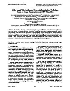
Maximum iterations = arbitrarily chosen as 100 Profit value = Minimum difference in values (10cm) obtained in the current and previous rounds. 9. Thus various cuckoos give different locations for a single node. Hence the average of the positions given by each cuckoo is estimated as the location of that particular node. The localization steps in the MCS-MAP algorithm so far discussed above can be pictorially represented as shown below in Figure 4.
5
International Journal of Computer Applications (0975 – 8887) Volume 95– No.6, June 2014
Fig 4: Flowchart for Localization steps used in MCS-MAP algorithm
6. SIMULATION RESULTS The following parameters namely, the number of mobile anchors, speed of mobile anchors, the number of sensor nodes and execution time are varied and the results were analyzed for each of the parameter variation in NS-2.
6.1 Simulation Setup The following simulation set-up as mentioned in Table 1 was maintained when the proposed Modified Cuckoo Search (MCS) Algorithm was applied over MAP algorithm and also to compare simultaneously with Cuckoo Search (CS) Algorithm when applied over MAP algorithm. From the various simulation studies made on Mobile Anchor Positioning (MAP), the following scenario is found as an optimum setup for providing minimal localization error. With the above simulation settings used in NS-2 as mentioned in Table 1, the results were analyzed to compare the performance of proposed Modified Cuckoo Search with Mobile Anchor Positioning (MCS-MAP) and Cuckoo Search with Mobile Anchor Positioning (CS-MAP) evolutionary strategies and the respective graphs were plotted.
Table 1. Simulation Settings Parameter Description
Value
Number of Sensor Nodes
100
Area of the Sensing Field
1000 X 1000 m2
Number of Mobile Anchors
3
Speed of Mobile Anchors
100 m/sec
Time interval between successive Anchors
1 sec
Execution time
500 sec
Transmission range
250 m
Routing Protocol
AODV
MAC Protocol
IEEE 802.11
6
International Journal of Computer Applications (0975 – 8887) Volume 95– No.6, June 2014
6.2 Metric used in determining the Localization Accuracy
6
The metric that is used to evaluate the accuracy in localization process is Root Mean Square Error (RMSE). The RMSE was calculated for both MCS-MAP and CS-MAP approaches by using the formula,
5
RMSE
n
x x act ( i )
i 1
y 2
obt ( i )
act ( i )
yobt (i )
3
RMSE value obtained using MCS-MAP
2
RMSE value obtained using CS-MAP
N (2)
Where, xact (i ) , yact ( i ) - represent the actual values of x and y coordinates of the sensor nodes.
1
- represent the obtained values x and y
coordinates of the sensor nodes and number of Localized nodes.
N - represents the total
0 10 20 30 40 50 60 70 80 90 100
xobt (i ) , yobt (i )
2
RMSE
4
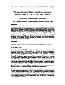
6.3 Comparison of RMSE obtained using MCS-MAP and CS-MAP approaches The accuracy in localization can be evaluated based on minimization in positional error. Root Mean Square Error (RMSE) is calculated for both MCS-MAP and CS-MAP approaches as listed below in Table 2. Table 2. RMSE Calculation for CS-MAP algorithm and MCS-MAP algorithm No. of Nodes
RMSE value obtained using CS-MAP
RMSE value obtained using MCS-MAP
10
5.423313
1.242948
20
3.647875
0.823340
30
3.151320
0.746681
40
2.781019
0.832958
50
2.566447
0.829156
60
2.292289
0.742992
70
2.079784
0.729530
80
2.018683
0.769892
90
1.946303
0.780737
100
1.826926
0.714813
From Table 2, pertaining to 100 nodes scenario on an average it is clear that the Root Mean Square Error (RMSE) drastically reduces when MCS-MAP algorithm is applied for localization when compared to that of CS-MAP algorithm applied for estimating the location of sensors.
Number of Nodes
Figure 5. Comparison of Root Mean Square Error values of MCS-MAP versus CS-MAP algorithms This observation shown in Table 2 has been graphically displayed in Figure 5 where, the x-axis indicates the number of nodes and the y-axis indicates the corresponding value of RMSE. It is clearly noted that RMSE value obtained using MCS-MAP algorithm on an average corresponding to 10, 20, 30 etc. up to 100 nodes scenario reduces when compared to CS-MAP algorithm.
7. CONCLUSION MAP uses range-free localization mechanism that does not involve usage of any hardware. In this method, messages containing location information are being shared among the nodes in the field and it does not require flooding and complicated computation for localization. The percentage of localized nodes is high which indicates that MAP method is appropriate for localization purpose. Since this method does not give fine-grained accuracy in localization, optimization techniques are applied on the results of MAP. In this paper, MCS-MAP algorithm has been applied over MAP to reduce localization error. From the simulation results pertaining to 100 nodes scenario, it can be noticed that on an average, the Modified Cuckoo Search with Mobile anchor positioning (MCS-MAP) algorithm significantly brings down the RMSE based localization error by 60.87 % (calculated by percentage error formula) when compared to Cuckoo Search with Mobile anchor positioning (CS-MAP) algorithm. Thus, it can be concluded that proposed MCS-MAP evolutionary approach is better than using MAP alone. Further, Hybrid cuckoo search algorithm can be applied instead of Cuckoo Search or Modified Cuckoo algorithm in order to minimize the localization error further. Moreover cuckoo search algorithm can also be combined with particle swarm optimization (PSO) and similar hybridization of optimization can be applied to further reduce the localization error.
7
International Journal of Computer Applications (0975 – 8887) Volume 95– No.6, June 2014
8. REFERENCES [1] I.F.Akyildiz, W.Su, Y. Sankarasubramanium, and E. Cayirci, “Wireless Sensor Networks: A Survey,” IEEE Computer., 2002, Vol. 38, Issue 4, pp.393 -422. [2] Jonathan Bachrach and Christopher Taylor, “Localization in Sensor Networks,” Chapter 9, “Handbook of Sensor Networks: Algorithms and Architectures,” Ivan Stojmenovic, 2006, pp. 277-297. [3] Guoqiang Mao, Barıs¸ Fidan , and Brian D.O. Anderson, “Wireless Sensor Networks Localization Techniques ,” Science Direct, Computer Networks 51, 2007, pp. 25992533. [4] Guibin Zhu,Qiuhua Li, Peng Quan; Jiuzhi Ye “A GPSfree localization scheme for wireless sensor networks “, 12th IEEE International Conference on Communication Technology (ICCT 2010), Nov 2010,pp. 401-404, doi: 10.1109/ICCT.2010.5688823. [5] Chaczko Zenon, Klempous Ryszard, Nikodem Jan, and Nikodem Michal, “Methods of Sensors Localization in Wireless Sensor Networks,” 14th Annual International Conference and Workshops on Engineering on Computer based Systems (ECBS 2007), Mar. 2007, pp. 145-152. [6] Hoang Q.T., Le T.N., and Yoan Shin, “An RSS comparison based Localization in Wireless Sensor Networks,” 8th workshop on Positioning Navigation and communication (WPNC 2011), April 2011, pp.116-121. [7] Pengfei Peng, Hao Luo, Zhong Liu, Xiongwei Ren “ A cooperative target location algorithm based on time difference of arrival in wireless sensor networks”, International Conference on Mechatronics and Automation (ICMA 2009), Aug. 2009, pp. 696-701,doi: 10.1109/ICMA.2009.524601. [8] Guowei Shen, Zetik R, Honghui Yan, Hirsch O., and Thoma, R.S.,“ Time of Arrival Estimation for rangebased localization in UWB sensor networks”, in Proc. of IEEE Int. Conf. on Ultra-Wideband (ICUWB 2010),Sept.2010,Vol.2,pp.1-4. [9] Yanping Zhu, Daqing Huang, and Aimin Jiang, “Network Localization using Angle of Arrival,” IEEE International Conference on Electro/Information Technology (EIT 2008), May 2008, pp. 205-210. [10] G.Yu, Fengqi Yu, L.Feng (2007), “A Localization Algorithm using a Mobile Anchor Node under Wireless Channel”, in Proc. of IEEE Int. Conf. on Robotics and Biomimetics (ICRB), Dec. 2007, pp. 1104-1108. [11] Binwei Deng, Guangming Huang, Lei Zhang, and Hao Liu, “Improved Centroid Localization Algorithms in WSNs,” 3rd International Conference on Intelligent System and Knowledge Engineering (ISKE 2008), Nov 2008, Vol. 1, pp. 1260-1264. [12] Zhang Zhao-yang, Gou Xu, Li and Shan-shan Huang, “DV Hop based Self-Adaptive Positioning in Wireless Sensor Networks,” 5th International Conference on Wireless Communications, Networking and Mobile Computing (WiCom 2009), Sept. 2009, pp. 1-4, doi: 10.1109/WICOM.2009.5301412.
[14] Qingguo Zhang, Jinghua Wang, Cong Jin,and Qingjiang Zeng, “Localization Algorithm for Wireless Sensor Network based on Genetic Simulated Annealing Algorithm,” in Proc. of 4th IEEE Int. Conf. on Wireless Communications, Networking and Mobile Computing (WiCOM) , 2008, pp. 1-5. [15] W-H Liao, Y.C.Lee, and S.P. Kedia, “Mobile Anchor Positioning of Wireless Sensor Networks,” IET communications, 2011, Vol. 5, Issue 7, pp.914-921. [16] Kuo-Feng Ssu, Ou, C.-H., Jiau, H.C.: ‘Localization with mobile anchor points in wireless sensor networks’, IEEE Transactions on Vehicular Technol, May 2005, Vol. 54, Iss. 3, pp. 1187–1197, doi: 10.1109/TVT.2005.844642. [17] Jia Huanxiang and Wang Yong, “Localization Algorithm for Mobile Anchor node based on Genetic Algorithm in Wireless Sensor Network,” Int. Conf. on Intelligent Computing and Integrated Systems (ICISS), 2010, pp.4044. [18] Han Bao, Baoxian Zhang, Cheng Li, and Zheng Yao, “Mobile Anchor Assisted Particle Swarm Optimization (PSO) based localization algorithms for Wireless Sensor Networks,” Wireless Communications and Mobile Computing, Oct. 2012, Vol. 12, Iss. 15, pp. 1313-1325. [19] RaminRajabioun and Elsevier B.V, “Cuckoo Optimization Algorithm”, Applied Soft Computing, Elsevier 2011, pp. 5508-5518. [20] Walton.S, Hassan.O, Morgan.K, and Brown.M.R, “Modified Cuckoo Search: A new gradient-free Optimization algorithm”, Chaos, Solutions and Fractals, Elsevier 2011, Issue 44, pp. 710-718.
AUTHORS PROFILE Mr.S.Sivakumar was born in Tamilnadu, India in the year 1977. He received his Bachelors degree B.E in Electronics and Communication from Bharathiyar University, Coimbatore in the year 1999.He completed his Masters degree M.E in Communication Systems from Anna University, Chennai in the year 2006. He is a part time research scholar at Anna University, Chennai. He is currently working as an Assistant Professor (Sr.Gr) in the Department of Information Technology at PSG College of Technology, Coimbatore, India. His research interests include Wireless Sensor Networks, Digital Signal Processing, Information coding Techniques and Networking. Dr.R.Venkatesan was born in Tamilnadu, India, in the year 1958. He received his B.E (Hons) degree from Madras University in the year 1980. He completed his Masters degree in Industrial Engineering from Madras University in the year 1982. He obtained his second Masters degree MS in Computer and Information Science from University of Michigan, USA in the year 1999. He was awarded with PhD from Anna University, Chennai in the year 2007. He is currently Professor and Head in the Department of Computer Science and Engineering at PSG College of Technology, Coimbatore, India. His research interests are in Simulation and Modeling, Software Engineering, Algorithm Design, Software Process Management.
[13] Patro, R.K. “Localization in wireless sensor network with mobile beacons”, 23rd IEEE convention of Electrical and Electronics Engineers Israel, Sept. 2004, pp. 22-24, doi: 10.1109/EEEI.2004.136107.
IJCATM : www.ijcaonline.org
8