use of expensive hardware. On the other hand, the ... point-to-point, the distance between each pair of nodes. With ... of a chord passes through the centre of the circle. ... W.-H.Liao et al. ... end points of a sensor node's communication range.
International Journal of Computer Applications (0975 – 8887) Volume 159 – No 7, February 2017
Error Minimization in Localization of Wireless Sensor Networks using Fish Swarm Optimization Algorithm S. Sivakumar, PhD Assistant Professor (SG) Department of ECE PSG College of Technology Coimbatore, India R.
Venkatesan, PhD Professor and Head Department of Computer Science & Engineering PSG College of Technology Coimbatore, India
ABSTRACT Node localization in wireless sensor networks (WSNs) is one of the most important primary requisite that needs to be resolved efficiently as it plays a significant role in many applications namely environmental monitoring, routing and target tracking which is location dependent. Localization is defined as finding the physical co-ordinates of a group of sensor nodes. Localization is classified as an unconstrained optimization problem. Localization protocols are broadly classified as range-based and range-free protocols. The range based protocols employ distance or angle estimation techniques, hardware. The range-free techniques depend on the contents of received messages to support coarse grained accuracy. In this paper, a range-free localization method known as Mobile Anchor Positioning - Mobile Anchor & Neighbor (MAP-M&N) is used to calculate the location of sensor nodes. Mobile Anchor equipped with Global Positioning System (GPS), broadcasts its coordinates to the sensor nodes as it moves through the network. As the sensor nodes collect enough beacons, they are able to calculate their locations. MAP-M&N with Fish Swarm Optimization Algorithm (MAP-M&N with FSO) is the proposed metaheuristic approach to calculate the location of sensor nodes with minimal error. Root Mean Square Error (RMSE) is used as the performance metric to compare between the two approaches namely, MAP-M&N and MAP-M&N with FSO. Simulation results reveal that MAP-M&N with FSO algorithm is effective to bring down the localization error to a bigger level when compared to using only MAP-M&N algorithm.
General Terms Localization in Wireless Sensor Networks.
Keywords Localization, NP-Hard, Mobile Anchor, Optimization, Root Mean Square Error;
Fish
Swarm
1. INTRODUCTION A Wireless Sensor Network (WSN) consists of spatially distributed autonomous sensors to monitor the physical or environmental conditions such as climate prediction, atmospheric pressure, etc. and it passes their data by using network to the desired location. They are usually deployed in huge numbers over the region of interest for object monitoring and target tracking applications. The more modern networks are bi-directional, also enabling control of sensor activity. The major inspiration behind the development of wireless sensor network was due to military applications such as battlefield surveillance and in the current scenario such networks are useful in many applications, such as process monitoring,
control and so on. Wireless Sensor Networks are useful only if sensor nodes are aware of the environment surrounding them. For each & every instance, each sensor could only monitor around its region and send the collected data to sink node [1]. The great prospective of Wireless Sensor Network lies in its ability to correlate the collected data in time and in space.
1.1 Localization Techniques Localization is defined as the process of making each sensor node in the sensor network to be aware of its geographic position. The simplest solution is attaching a GPS to each sensor node. But attaching GPS to every sensor is costly. Localization serves as one of the most critical issue in wireless sensor networks, because the location information is typically useful for coverage, deployment, routing, location service, target tracking and rescue operations [2]. As the sensor nodes are small, inexpensive, co-operative and deployed in large quantities, there exist unique challenges and opportunities for WSN localization. Localization algorithms [3] are broadly classified into two categories: range-based and range-free algorithms. The rangebased algorithms employ distance or angle estimation techniques to achieve fine-grained accuracy, which require the use of expensive hardware. On the other hand, the range-free techniques depend on the contents of received messages to support coarse-grained accuracy. In recent years, a large number of range-based and range-free algorithms have been proposed for WSN localization. Most of these algorithms share a common feature in that they estimate the locations of the sensor nodes with initially unknown positions (target nodes) using apriori knowledge of the absolute positions of a section of nodes (anchor nodes) and inter-sensor measurements [4]. Distance estimation: This phase involves measurement techniques to estimate the relative distance between nodes. Position computation: It consists of algorithms to calculate the coordinates of the unknown node with respect to the location of known anchor nodes or other neighboring nodes. Triangulation, multilateration, and proximity are some techniques that are used for location sensing. It uses the geometric properties of triangles to calculate node locations. Triangulation is classified into lateration, using distance measurements and angulation, using bearing angle information. In 2-dimension to calculate the node location using lateration distance information from three reference points is required and using angulation two angle measurements and one distance information is required.
39
International Journal of Computer Applications (0975 – 8887) Volume 159 – No 7, February 2017 Localization algorithms: It determines how the information concerning distances and positions, is manipulated in order to allow most or all nodes of WSN to estimate their position. Optimally the localization algorithms may involve algorithms to reduce the errors. In this paper, a range-free localization method known as Mobile Anchor Positioning with Mobile Anchor & Neighbor (MAP-M&N) was applied to localize the sensor nodes and then the proposed meta-heuristic Fish Swarm Optimization algorithm was used along with MAP-M&N. The average error during localization was analyzed using these two algorithms.
1.2 Fish Swarm Optimization Reza Azizi, Hasan Sedghi, Hamid Shoja, et al. [5] developed Fish Swarm Optimization based on collective movement of the fish and their various social behaviors. FSO is one of the best methods of optimization among the swarm intelligence algorithms. This algorithm is inspired by searching for food, immigration and dealing with dangers all happen in a social form and interactions between all fish in a group will result in an intelligent social behavior. This algorithm has many advantages including high convergence speed, flexibility, fault tolerance and high accuracy. Fish Behaviors in Fish Swarm are free-move behavior, prey behavior, follow behavior, swarm behavior and chasing behavior.
2. RELATED WORK 2.1 Range-Based Localization Method Nabil Ali Alrejeh et al.[6] have proposed range-based and range-free localization techniques. These techniques estimate, point-to-point, the distance between each pair of nodes. With this information and using techniques, such as multilateration, triangulation or other methods, the absolute position of the non-anchor nodes can be estimated. Lovepreetsingh et al. [7], described about Received Signal Strength Indication (RSSI) [8], Time of Arrival (ToA) [9], Time Difference of Arrival (TDoA) [10] and Angle of Arrival (AoA) [11] techniques for localization. New algorithms continue to appear based on these classical methods for the improvement of accuracy, for example, based on AoA, based on ToA and based on TDoA. Several authors propose a range-based algorithm that uses a likelihood calculation for determining the distance. Received Signal Strength Indication: It requires no additional hardware, and are unlikely to significantly impact local power consumption, sensor size and thus cost. Time Difference of localization algorithms transmitter’s signal at location information transmitter.
Arrival: There is a category of utilizing TDoA measurements of the a number of receivers with known to estimate the location of the
Time of Arrival: In this technique cross co-relation method is used to estimate the location of the sensor node. Angle of Arrival: The beam of the receiver antenna is rotated electronically or mechanically, and the direction corresponding to the maximum signal strength is taken as the direction of the transmitter. Relevant parameters are the sensitivity of the receiver and the beam width. In general, the range-based ones offer good accuracy, but additional hardware is often needed. Therefore, the weight, the cost and the power consumption of the node devices increase and make these techniques unsuitable for the proposed application.
2.2 Range-Free Localization Method Range-free or proximity based localization schemes rely on the topological information, e.g., hop count and the connectivity information, rather than range information. Range-free localization schemes may or may not be used with anchors or beacons. A range-free localization scheme does not involve in the use of complex hardware and are cheaper when compared to range-based schemes. Radio coverage membership An anchor node detects whether a non-anchor node is in its radio coverage. Using this information, the system can estimate the non-anchor node position as a function of the intersection of the coverage areas of every anchor node that are in its radio coverage and intersection of the coverage areas between the two anchor nodes. Number of hops to an anchor-node If there is no connectivity with an anchor node, a non-anchor node can estimate its position knowing the number of hops to every anchor node. An example of that is Node A is at a distance of two hops to anchor node one, three hops to anchor node two and two hops to anchor node three. According to this information and considering the mean distance between the nodes, the absolute position can be calculated by applying algorithms, such as triangulation. Some commonly used range-free localization techniques are Centroid Algorithm [12] Distance Vector Hop (DV-Hop) [13], Approximate Point-In Triangulation Test (APIT), etc. Kuo-FengSsu et al. [14] presented a range-free algorithm, which uses the following conjecture. A perpendicular bisector of a chord passes through the centre of the circle. When there are two chords of the same circle, their perpendicular bisectors will intersect at the centre of the circle. A mobile anchor moves around the sensing field broadcasting beacons. Each sensor node chooses two pairs of beacons and constructs two chords. The sensor node assumes itself as the centre of a circle and determines its location by finding the intersection point of the perpendicular bisectors of the constructed chords. W.-H.Liao et al. [15] describes many range free localization techniques. In range-free localization methods neighborhood information such as node connectivity and hop count is used to determine node locations. Range-free methods [16] do not require additional hardware, but they generally only work well when networks are dense. Sparse networks by nature contain less connectivity information and are thus more difficult to localize accurately. These algorithms require that each node knows which nodes interact with each other i.e. in the communication range of each other, their location estimates and ideal radio range of sensors. Range-free techniques are most cost-effective because they do not require sensors to be equipped with any special hardware but use less information than range-based. The current trend is to realize the performance of metaheuristic algorithms [17] for localization.
3. PROPOSED LOCALIZATION APPROACH The proposed localization approach used in this work can be visualized to work in two phases. In the first phase, a rangefree algorithm namely Mobile Anchor Positioning with Mobile Anchor & Neighbor (MAP-M&N) is used for determining the location of the unknown sensor nodes. In the second phase, a swarm intelligence optimization algorithm [18] named as Fish Swarm Optimization (FSO) algorithm is
40
International Journal of Computer Applications (0975 – 8887) Volume 159 – No 7, February 2017 applied over the results of MAP-M&N algorithm for enhancing the localization accuracy of sensor nodes and for further direction of improvement.
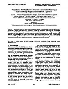
3.1 Mobile Anchor Positioning (MAP) The simulation environment is set-up as follows: The sensor nodes are randomly deployed in the sensing field. Mobile anchors are location aware nodes that move in the sensing field, fitted with GPS. As they move around the sensing field, they periodically broadcast messages containing their current location at fixed time interval to all the nodes, which are at a hearing distance from it. Such messages are known as beacons. The mobile anchors traverse around the field with a specific speed and their directions are set to change for every 10 seconds. All the nodes in the communication range of the mobile anchor will receive the beacons. A sensor node will collect all the beacons in its range and store it as a list. Communication range of the sensor node and the mobile anchor node are assumed as same. Once enough beacons are received and if a sensor node does not receive a beacon, which is at a distance greater than the already received ones, the localization begins at that particular node. Assume that the sensor node has received and stored four beacons (locations of the mobile anchor) in its list {T1, T2, T3, and T4} (refer Fig.1). From the list, two beacons, which are farthest from each other, are chosen (T1, T4). These points are known as Beacon points. These two points are marked as the end of the sensor node’s communication range since the sensor node has not received a beacon farther from this point. Hence T1 and T4 (Beacon points) represent either two positions of the same mobile anchor or positions of two different mobile anchors when they were at the end of the sensor node’s communication range. With these two Beacon points as centers and the communication range of a sensor node as radius, two circles are constructed (refer Fig.1). Each circle represents the communication range of the mobile anchor, which has sent the beacon. The sensor node has to fall inside this communication range, as it has received the beacon. Since the sensor node has received packets either from both anchors or from the two positions of the same anchor, the node has to fall inside both the circles. Hence, it can be concluded that circles will intersect each other. The intersection points of both circles are determined (S1, S2). The intersection points are the possible locations of the sensor node. The two farthest points (Beacon points) are the end points of a sensor node’s communication range. Thus in the circle with mobile anchor’s position as the center and the communication range of a node as the radius, the sensor node will be in the circumference of the circle.
T2
T5 S1
T3
T2 T1
T4
T6 S2
Possible locations of the sensor node Beacon points Beacon packets Fig 1: Possible Locations of the Sensor Node The sensor node lies on the circumference of the other circle since it is the same with the other mobile anchor position. Therefore, the sensor node lies on the circumference of both the circles. The only points satisfying the above condition are the two intersection points. Hence, by means of Mobile Anchor Positioning, the location of the sensor node has been approximated to two locations.
3.1.1 Identifying Sensor Locations using MAP-M The visitor list is searched after identifying the two possible positions i.e. the intersection points. If a node could hear around its range, there is a possibility of a beacon point which can be situated at a distance r from one of the two possible locations. Thus, there is one point in the list, whose distance from one possible location is less than r, and the distance from other possible location is greater than r, then the first possible location is chosen as the location of the sensor node. It is assumed that the communication range of a mobile anchor is R. The MAP-M maintains the visitors list after receiving the beacon packets from the mobile anchor. The information from the visitor list is used to approximate the location of the sensor node. Let the visitor list of a sensor node S consists of various location information represented as {T1, T2… Tn}. The beacon points are the two extreme points i.e., T1 and Tn. Two circles with radius R and center T1 and Tn are constructed and their intersection points of two circles are found to be S′ and S′′. If there is any Ti (2 ≤ i ≤ n-1), such that the distance between Ti and S′ is less than R and that between Ti and S′′ is greater than R, then we can conclude the location of the sensor node is S′. This is because of the fact that the sensor node should lie inside the communication range of mobile anchor to receive the beacon packets. Consequently, the distance between the sensor node S and beacon packet Ti should be less than R. There is an area named as the shadow region, as shown below in Fig 2.
41
International Journal of Computer Applications (0975 – 8887) Volume 159 – No 7, February 2017
3.2 Localization Steps followed with MAPM&N
T1
It is possible for the sensor nodes that have already determined their location to assist other nodes in determining their locations. As soon as the location is identified, the localized nodes start acting like anchors. They embed their calculated location inside the packet and then broadcast the beacons. Nodes, which are at its hearing range and waiting for additional beacons to finalize their location, can make use of these beacons. However, if the sensor node has determined its location, it simply discards the beacon packet. Thus by using MAP-M&N method, the cost of movement of the mobile anchor can be reduced.
T4
The steps in finding the location of the sensors in the field using MAP – M & N are listed below:
Figure 2: Shadow Area If all the Beacon points lie inside this region, it is not possible to determine the location of the sensor as the shadow region comes under the range of both the intersection points. This could be explained by drawing two circles with S' and S" as center and the shadow region is the intersection of the two circles. Hence, in order to estimate the location of the sensor node there is a need that at least one of the beacon packets in the visitor list must lie outside the shadow region, as shown in Fig.3.
1.
Deploy 100 sensor nodes randomly in the 1000 m x 1000 m area of the sensing field in the simulation environment and deploy 3 location aware nodes (anchor nodes) i.e sensor nodes fit with GPS.
2.
The anchor nodes move through the entire sensing field based on a movement file. The anchor nodes periodically broadcast their location packets, which are known as beacon packets, while on the move throughout the sensing field.
Consequently it is not possible to determine the location of the sensor node S using the available beacon packets, thus the node is made to wait until it gets further beacon packets. If no further beacons are obtained, then a single position of sensor node S cannot be obtained. Thus, the node will have two positions namely, S' and S". To overcome this problem, the method of Mobile Anchor Positioning with Mobile Anchor & Neighbor (MAP-M&N) is being applied. The location estimation for sensors using MAP-M method gives positions for few sensors and for the others, it gives two positions and so it is the responsibility of MAP-M&N method to produce outputs with a single position for each sensor.
3.
Every sensor node maintains a visitor list containing beacon packets based on the information obtained from anchors.
4.
The sensor nodes can identify the farthest beacon packets and chooses those beacon packets as beacon points.
5.
With those two beacon points as the centers and the communication range of a sensor node as radius, two circles are constructed and the intersection points are found.
6.
Sensor nodes try to identify its position out of the two intersection points. Here, at least one of the beacon points in the visitor list must lie outside the shadow region or based on the beacon points obtained from neighbor nodes.
7.
The approximate location for each of the sensor nodes is found using the MAP - M & N method.
S’ T6
T1
T3
T4
T5
T2
3.3 Localization steps used in Mobile Anchor Positioning with FSO Algorithm The steps followed while performing localization in MAPM&N with FSO algorithm are: 1.
S’’ 2. 3. S’ and S’’ indicate the possible locations of the Sensor node Beacon packets Figure 3: Node Seeking Information from Neighbor Sensors
4.
Initialize a population of particles with random positions. Calculate the fitness value for the given objective function for each particle. Current position of AF is taken as vector X=(x1, x2, …, xn) The visual is equal to visibility domain of AF and AF move towards Xv which is an intended position in visual. Food density in position X is the fitness value of the position and is shown with f(X)
𝑥𝑖 𝑡 + 1 = 𝑥𝑖 𝑡 + 5.
𝑥 𝑗 −𝑥 𝑖 𝑡 𝐷𝑖𝑠 𝑖,𝑗
∗ 𝑠𝑡𝑒𝑝 ∗ 𝑟𝑎𝑛𝑑𝑜𝑚 0,1 (1)
From equation (1) it is inferred that the food density in 𝑋𝑖 is compared with that of the current position,
42
International Journal of Computer Applications (0975 – 8887) Volume 159 – No 7, February 2017 if f(𝑋𝑖 ) ≥ f(𝑋𝑗 ), AF i moves forward a step from its current position to 𝑋𝑗 .
4. SIMULATION RESULTS The following are the simulation parameters used in ns-2 for result analysis as shown in Table 1: Table 1: Simulation Settings
Table 2: RMSE for MAP-M&N and MAP-M&N with FSO Algorithm No. of
RMSE for
RMSE for
Nodes
MAP-M&N
MAP-M&N with FSO
10
503.54
96.87
Parameter Description
Value
Number of Sensor Nodes
100
Area of the Sensing Field
1000 X 1000 m2
Number of Mobile Anchors
3
20
512.33
89.23
Speed of Mobile Anchors
100 m/s
30
560.11
72.45
Time interval between successive Anchors
1s
40
612.34
65.45
Execution time
500 s
50
562.45
90.34
Transmission range
250 m 60
523.45
87.54
Routing Protocol
AODV
MAC Protocol
IEEE 802.11
70
673.45
74.76
80
598.54
65.76
90
500.45
75.76
100
450.45
69.50
The topology setting is given as the input. It consists of details like x dimension, y dimension, number of unknown sensor nodes, number of mobile anchor nodes and the routing protocol used. It also includes the simulation period, radio range at different levels. With the simulation settings of ns-2 as shown in Table 1, the results were analyzed for both MAPM&N and MAP-M&N with FSO approaches.
4.1 Performance Metric to find Localization Accuracy The metric that is used to compare the accuracy obtained from MAP-M&N and MAP-M&N with FSO Algorithm is Root Mean Square Error (RMSE). The RMSE was calculated for both approaches using the formula, RMSE= 𝑥𝑎𝑐𝑡
𝑥𝑜𝑏𝑡 𝑖 ,𝑦𝑜𝑏𝑡 𝑖 - Obtained values of x and y coordinates of sensor nodes and N - Total number of localized nodes
𝑖
,𝑦𝑎𝑐𝑡
𝑛 𝑖=1 𝑥 𝑎𝑐𝑡 𝑖 −𝑥 𝑜𝑏𝑡 𝑖
2
𝑁 𝑖
+ 𝑦 𝑎𝑐𝑡 𝑖 −𝑦 𝑜𝑏𝑡 𝑖
2
(2)
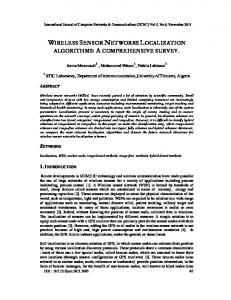
RMSE is calculated using equation (2) for both MAP-M&N and MAP-M&N with FSO approaches pertaining to every ten nodes scenario as listed in Table 2. Figure 4 depicts the graphical representation of RMSE value of MAP-M&N and MAP-M&N with FSO Algorithm as obtained in Table 2. It is observed from Figure 4, that the RMSE is drastically reduced when Fish Swarm optimization algorithm is used along with MAP-M&N when compared to the RMSE value that is obtained using MAP-M&N alone on an average for 100 nodes scenario.
- Actual x and y coordinates of sensor nodes
43
International Journal of Computer Applications (0975 – 8887) Volume 159 – No 7, February 2017
800 700 600
RMSE
500 400 MAP-M&N MAP-M&N with FSO
300 200 100 0 10
20
30
40
50
60
70
80
100
No. of Nodes Figure 4: Comparison Graph for RMSE of MAP-M&N with FSO versus MAP-M&N algorithm
5. CONCLUSION
6. REFERENCES
Mobile Anchor Positioning uses the range-free localization method which does not involve the usage of any hardware. The percentage of localized nodes is high which highlights that MAP algorithm is efficient for localization. However, since this method does not provide fine-grained accuracy in localization, swarm intelligence optimization technique named Fish Swarm optimization algorithm is applied over the results of MAP-M&N. From the experimental results of these two algorithms, Mobile anchor positioning with Fish Swarm optimization algorithm significantly brings down the RMSE based localization error on an average for 100 nodes scenario by 85.4% when compared to MAP-M&N. Consequently it is obvious that the localization error was significantly reduced while using MAP-M&N with Fish Swarm optimization when compared to MAP-M&N. The future work can be hybridization of Particle Swarm Optimization (PSO) combined to MAP-M&N with FSO algorithm. The localization error of the new hybrid evolutionary algorithm can be compared to MAP-M&N with FSO algorithm to validate its performance. Similar hybridization of optimization can be applied to have significant reduction in percentage of localization error.
[1] Ahmad AA Alkatib, Gurvinder S Baicher, Waleed K Darwish, “Wireless Sensor Networks: An Advanced Survey”, International Journal of Engineering and Innovative Technology (IJEIT), Vol 2, Issue 7, January 2013. [2] Guibin Zhu, Qiuhua Li, PengQuan, Jiuzhi Ye,“ A GPS free localization Scheme for Wireless Sensor Networks”, 12th IEEE International Conference on Communication Technology (ICCT 2010), pp.401-404, Nov 2010. [3] Guoqiang Mao, Barıs¸ Fidan , and Brian D.O. Anderson, “Wireless Sensor Networks Localization Techniques ,” Science Direct, Computer Networks 51, pp. 2599-2533, 2007. [4] Anil Kumar, Arun Khoslay, Jasbir Singh Saini, Satvir Singh, “Meta-Heuristic Range Based Node Localization Algorithm for Wireless Sensor Networks”, Proceedings of IEEE International Conference on Localization and Global Navigation Satellite Systems (ICL-GNSS), Starnberg, pp. 1-7, 2012. [5] Jie Hu, Fresh Educ. Dept., Yangtze Univ., Jingzhou, China; XizngjinZeng, JiaqingXizo, “Artificial Fish School Algorithm for Function Optimization”, Proceedings of 2nd International Conference on Information Engineering and Computer science (ICIECS 2010), Dec. 2010. [6] Nabil AliAlrajeh, Maryam Bashir and Bilal Shams, “Localization techniques in wireless sensor networks”,
44
International Journal of Computer Applications (0975 – 8887) Volume 159 – No 7, February 2017 International Journal of Distributed sensor networks, 2013. [7] Love preet Singh, Sukhpreetkaur, “Techniques of nodelocalization in wireless sensor networks: Review”, International Journal of innovative Research in Computer and Communication Engineering,Vol.2,Iss. 5, May 2015. [8] Hoang Q.T., Le T.N., and Yoan Shin, “An RSS comparison based Localization in Wireless Sensor Networks,” 8th workshop on Positioning Navigation and communication (WPNC 2011), pp.116-121, April 2011. [9] GuoweiShen, Zetik R, Honghui Yan, Hirsch O., and Thoma, R.S.,“ Time of Arrival Estimation for range based localization in UWB sensor networks”, in Proc. of IEEE Int. Conf. on Ultra-Wideband (ICUWB 2010), Vol.2, pp.1-4, Sept.2010. [10] PengfeiPeng, HaoLuo, Zhong Liu, XiongweiRen “A cooperative target location algorithm based on time difference of arrival in wireless sensor networks”, International Conference on Mechatronics and Automation (ICMA 2009), pp. 696-701, Aug. 2009. [11] Yanping Zhu, Daqing Huang, and Aimin Jiang, “Network Localization using Angle of Arrival,” IEEE International Conference on Electro/Information Technology (EIT 2008), pp. 205-210, May 2008. [12] Binwei Deng, Guangming Huang, Lei Zhang, and Hao Liu, “Improved Centroid Localization Algorithms in WSNs,” 3rd International Conference on Intelligent System and Knowledge Engineering (ISKE 2008), Vol. 1, pp. 1260-1264, Nov 2008.
IJCATM : www.ijcaonline.org
[13] Zhang Zhao-yang, Gou Xu, Li and Shan-shan Huang,“DV Hop based Self-Adaptive Positioning in Wireless Sensor Networks,” 5th International Conference on Wireless Communications, Networking and Mobile Computing (WiCom 2009), pp. 1-4, Sept. 2009. [14] Kuo-FengSsu, Ou, C.-H., Jiau, H.C.: “Localization with mobile anchor points in wireless sensor networks”, IEEE Transactions on Vehicular Technology, Vol. 54, Issue 3, pp. 1187–1197, May 2005. [15] W-H Liao, Y.C.Lee, and S.P. Kedia, “Mobile Anchor Positioning of Wireless Sensor Networks,” IET communications, Vol. 5, Issue 7, pp.914-921, 2011. [16] Chi-Chang Chen, Yon Nong Li, Chi Yu Chang, “A novel range-free localization scheme for wireless sensor networks”, International journal on applications of graph theory in wireless ad hoc networks and sensor networks (GRAPH-HOC), Vol.4, No.2, pp. 1-13, Sept. 2012. [17] Aloor Gopakumar and Lilly kutty Jacob, “Performanceof some meta-heuristic algorithms for Localization in Wireless Sensor Networks”, Int. Journal of Network Management, Vol.19, Issue 10, pp. 355-373, 2009. [18] R.Azizi, H.Sedghi, Hamid Shoja, A.S.Moghaddam, “A Novel Energy Aware Node Clustering Algorithm for Wireless Sensor Networks using a Modified ArtificialFish Swarm Algorithm”, Int. Journal of Computer Networks & Communications, Vol.7, No.3, pp.103-115, May 2015.
45