.
.
SPE/DOE Scclotyof
Potroloum Engineers
U.S. Department o?Enarsy
SPE/DOE 20241 Experimental Validation of a New Method for Optimizing Miscible Flooding of Stratified Reservoirs P, Ingst$y, Rogaland Research Inst., and SM. Sklaeveland, Rogaland u. Centre SPE Members
Copyright 1990, Scdety of Petroleum Enginwm Inc. This paper waa praparad for presentationat the SP13DOEseventh SymPcsiumon Enhanced oil Recoveryheld in TUISS.Oklahoma,APril Z2-25. 1990. This papar was eelected for preaanta!lonby an SPE prcgrem Commlffae followin9 review of information ccntalned in an abstract aubmifted by the author(s).Ccntente of the paper, as preeenwd, heve not been reviewedby the Society of Petroleum Engineersand are subject to correction by ths author(s).The material, as presented,does not necessarilyreflect any position of the SccIetyof PetroleumEngineers,Ite officers,or members.Paperspresentedat SPE meetingsare subject to publication reviewby Editorial Committeesof the Society of not morethan S&3wcfda. llluafratirmemaynot be
[email protected] abstractehculdcontainccnapkucuaeckwwladgfnant of PetroleumEnglnam. Permkalonto CCPYk restrictedtomabstract of where and by whom the paper k preeentad.Write Publicatlone Mna9ar, SPE, P.O. BOXrJWIS6, Richwdecn, n 7WW3r13e. Telex, 7S0989SPEDAL.
L ABWRACI
~xu&uI~phenomenonassociatedwithviscousmixing,discussedin .
Miscible displacementexperimentswere conductedin a stratified model reservoirs that permitted visual observation of the flow processes.Concentratingon favorablemobilityratiodisplacements, the results are analyzed by a VE theory which includes gravity effectsl s2. The results show that tie front shape, ~d hen= tie reeovery,of gravity stable displacementscan be predictedby the theory. Further, rates for breakdownof gravity stabilization are predictedin agreementwith experimentalresults. It is shown that channelinof the injectionfluidintohighpermeabilitylayersmaybe stabilizef by viscous cross-flow, even during relatively high injeetionrates.Observationof unexpectedlylargemixingzonesare explainedas viscousmixingcausedby crossflowbetweenlayers.
Severalexperimentsin stratifiedmodelshave been reportedin the petroleum literature. Starting in the fifties, experimenters have demonstrated the importance of cross-flow3 ad gravity segregation45$. The presenceof high permeabilitylayersend the location of such layers have been shown to influence recovery severely in some c~ess. UntiJ recently, the experimentalresults were usedqu~i~tively, or a physic~ modelwas us~ ss an ti~og computer,and measuredresults were transformedby scalingrules and appliedto the specrlc reservoirs.
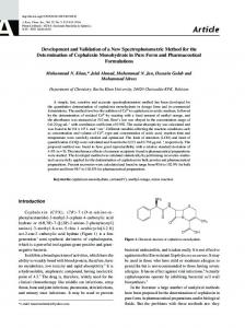
Recently,attemptshavebeenmadeto approachfloodingof stratified modelsquantitativelywithanalyticalmethods7-10.Quintsrdet al.‘O used the theory of large scale averaging to develop pseudoproperties, and was able to predict experimental water flood performance.Their solution,however,assumesthat gravitycan be me verticalsweepefficiencyobtainedduringmiscibleinjeetionin neglected as compared with capillary forces. A successful stratified reservous with communicatinglayers depends on both quantitativetzeatmentof the misciblecase,includinggravity,has, to avity and viscousforces,The combinedeffectof theseforceshas r een studied by numerical methods and in glass bead or sand our knowledge,not beenpresented. models3- 10. In some ewes a gravi~ stabilized front may be Following Marle13 and Ekrannl*2,we will adopt the followini obtainedg.In othereases,gravitycausesgrowing“fingers”(gravity terminology:A displacementis said to be stationary if the fronl over- or undernde), or viscous forces cause the injection fluid to moves through the reservoir withoutchanging its shape13. If tix channel through high permeability layers. Some of these front is monotonically depressing (S1OPCalways ne@iv) 01 observations, together with theoretical developments1J2,11, monotonically increasing (slope always positiv), it 1s called suggest that important properties of the displacement may be segregated. A segregatedstationaryffontis calledgrwity-stabilizti quantitativelyanalyzedby methodsbasedon the so-csll@ vertical ifgrsvity causesthedenwr fluidto underndetie 1SS dense. equilibrium(W) assumption 1)12. Treatingimmisciblepiston-likedisplacements,Ekrannlz2has used“ VE theory to describethe front shape, and heneereeove~, in the gravity stabilized case. Further,he has pledicteda eriticelmjeetion The ex~erimentswere carriedout in a two-dimensionaltrsnspsren rate “above which gravity stabilization is not ~ossible, and the cell using glass beads as the porous medium. !$tratifxcationwa[ obtainedby using differentgradebeadsin the differentlayers.TIN injectionfluidstartschannelingintohighpenneabditylayers. cell was moundet vertically to allow for gravity effeets. Fig. ; “ entalresultsarepresentedhereto verifysuchapplicationsof showsthe experimentalsystem,and definesthe coordinatesysten ‘r theory in miscible systemswith ~avity. The results are used used in this study.The innerdimensionsof the cell were 125by 3[ also to discussthe developmentof a dsplseement underconditions by 1.7cm. when the theory does not apply. The fwus in this study is on viscous and gravity forces only, mixing is negleetedexeept for a A pseking teehnique14was developedthat produced bead pack 04
EXPERIMENTALVALIDATIONOFA NEWMETHODFOR nPmMrzmJ~, ~lYN~ .- OF . . . ..— .-.. MTSCTRT -.—— F?H ------- SIT? -... A?TFI133 .-— — REfJl?RV~TRS -—.—. . -.. —
2
.
. SPE 20241
M porositks in the 36-3870 range, ~d flowed he layers to be wh~~ L is the leng~ (~ong s~~lcation) of the ~emoir, H k the nde with a fairly constant height(thickness),approximatelyMS height,andthe averagePermeabilitiesaredefinedas m. .. (3) le displacementexperimentswerecamiedout usinga salt solution nd distilledwater.Eitkerthe displacingor the displacedfluidwere olored, and the displacement process was recorded by Photographingor videorecording.Reasonable sharp fronts were sually observed so that the front position could be determined (4) * vithina 3- S cm interval.The pressuredistributionin the cellcould Ie measured through six holes (Shown in Fig. 1) drilled in the Jastic plates ~d connectedto differentialpressuretransducersor manometers.The pressuredifferenceswererelativelysmall, in the angeS -15 millibar,and considerableeffortwas neededto obtain Zapata and Lakel 1 have shown that the VE assumption is a eliablevalues. reasonableapproximationfor viscously-dominatedcasesprovided RLis greaterthan about 10.Note tim Table 1 that modelsused in rhe salt solution was made by dissolving sodium sulphate this study had RL ratios significantly lower than this, i.e. in the Na2S04) in water.Thedensitywasin the range 1.17-1.19g/cm3- range 2.5-3.6. i%eviscosity was in the rmige 1.8 -2.0 mPas, the S%,variation }eingintroducedby roomtemperatureandconcentrationvariations. Assumingthe distributionof saturationin the reservoiris given (a t followsthat themobilityratiocanbe estimatedas degree of freedom that must be removed later for practical applications),it is a simpletaskto developan expressionfor U* the 0.50 * 0.04, x componentof the fluiddarcyvelocityanywherein thereaemoir12 This result can be used to develop a method based on pseudo inthefavorablecase,and functions.We choosenot to follow this path in the analysisof OUI data, since it can be shown13 that the introductionof signifkan 2.0*0.1, gravity effects may make the equation for the pseudo-saturatio~ parabolicandhenceunsuitedfor the methodof characteristics. inthe unfavorable. The model geometriesunder study were divided into four groups Analyzingimmiscibledisplacements,Ekrann’stheoryis restrictedtc K31-G4),see Table 1. Note that the layers are numberedfrom the monotonically decreasing or increasing fronts which locally an bottom an up.llte porosities of the different layers could not be considered to be piston-likel J2. The fluid are considered measuredaccuratelyin the cell,andwerethereforedeterminedfrom incompressible.Mathematically,he arrivesat VEb takingthe lid separateporositymeasurementsin columns.Theresultsare givenin of intlnitepermeabilityin the vertical(y)direction.L the absenceoj Table 1. The error introducedby using the column results can be dispersion,Ekrann’sresultsmay 5e applieddirectlyto the misciblt assumedto be small, i.e. some 5%, since the porosity of normally case. packed glass beadsdo not varya greatdeal15. Under the assumption of infMe vertical permeability, Ekram Theperrneabilitiesof thebeadpacks(Table1)weremeasuredin-situ develops an equation describingthe shape of a gravity+abilim using a dye as a nonadsorbing tracer in the distilled water to decreasingfrontl ~2.With the deftitions given in Appendix1, thi obtainedthe average fluid velocity directly.l%esedisplacements equationcanbe written werealso used as qualitycontrolof the uniformityof each layerin the bead pack, The permeabilitymeasurementsare expectedto be accuratewithin 10!ZO. (5) Mostof the experimentswere duplicated,and the results from the wcond displacementwere always consistent with what had been Here, h(x,t) is a function describing the front (Fig. 1), q is tit previouslyobtained. volumetricinjectionrate and Az is the extensionof the reservoiri the z-direction.Ap is the densitydifferencedefinedas the densitya the displacingfluid minus the density of the displacedfluid. Th functionsdenoted,. +z (withsubscript)representintegralsover th A Vertical EquilibAurntheoxymay be developed based on the assumptionthat Suin of all fluiddrivingforcesin the vertical(cross- reservoir porosity, a]d the functions denoted by a and b (vW the mobility of the disphtcizq dip) direction is zero12. A consequenceof this is that the flow- suhscripts)representintegralaover ~~1displ~ed fluid, r~pectiveiy. Note from Appendix 1 d..t th~ potentialmust be a fimctionof x onlylJ2J2: on!yfree variableat the right handside of Eq. 5 is x whichappear Vj= Pj(Pj+8~x
(1)
+ SyYl
throu h h(o)(x).We will refm to the solutiongivenby Eq. 5 as th VE(Of solution.
5 giveathe solutionfor a monotonicallydecreasingfion~ Th HerePj is the &naity of phasej =dpj is the pressure.g%andgy are Eq. corresponding quation for an increasing front is obtained b: thex anay componentsof ~$ty. interchangingsubscriptsu ando. Deftig thereservoireffectivelengthto heightratioas —In L~
‘L=F
~ ()
9
: (2)
F~. 5 holds strictly for the case of infinite PerrneabilikyirI the y Ekrannls2 uses this solution to develop M direction. approximation,h(l)(x,t), for the real fiong I@@,in a system witi finiteverticalpermeabiliqu
.
. .
:-~-Apgy
[n these displacements, with M close to 0.5, the dense fluid tisplacedthe less dense, and gravity stabilizationrequiredgtw@ ,mdexride.
Here,and in the following, subscriptsa and b denote displacing M displaced fluid, respectively. U(0)Y=and U(o)yb are they bmponentsof the darcy velmitiy at the point (x,h(x)) on the fron~ slculated for the infinite vertiti permeability case @q. 5), see PIX@X 1.~~ and +b am thenobilities at the samepoin~In the >Ilowing,the solution given by Eq 6 is referred to as the VE(l) Nution.
Nationsryfronts were observedin all the low rate displacements :xccptEx@ment 3 wherethepmiicted gravitystabilizedfrontwas longer than the model reservoir. The observed stationary front ;hapesagreedreasonablywell with predictionsbasedon Eqs. 5 and 5,except for points netmthe boundariesbetweenthe layers.Here, thin tongues were observed to forme, see Figs. 2 and 4. Tlie Iongueswere some 1-3cm thick but did stabilize.In spite of these iongues (which strictly violate the requirement of gravity segregation)we stillCISSSNthesefkontsas gravity-stabilized.
iq. 6 is based on r uirihg pressure continuity along the isplacement tint h(l7 (x,t) in the system with finite vertical ermeability while approximatingthe darcyvelocitiesat the front titb the VE(~)velocities. Veextendthe theoreticalmodelslightlyby repeatingthis argumen~ gain requiringpressurecontinuity,and usingthe velocitiesU(l)ya nd U(l)ybcalculatedfkomthe VEO)solution(See Appendix1),to Ievelopa new approximationof thefront E- ~h(~ )% -Z-=
-AP8Y U(O N >.~.
ah(l) T
MIseenfkomFig. 2, Experiment1, the predictionsbased on Eqs. 5, 6 and 7 agreereasonablywell with the obstnvations,the differences betweenthe threetheoreticalpredictionsbeingsmall.FromTable2, therate, 0.167cm3/min(0.44ftlday),was well below the flcted rates for breakdownof gravitystabilization.Figure2 cont!rrna that in this case the recove~ can be approximately calculated by integrationof Eq. S or 6. The results obtainedfrom Experiment 1 sre consistent with @iminary results from a nearly similar expenrnengpresentedm Ref 9.
(7)
Fig. 3, Experiment2, showsa gravitystab~ frontobtainedin a threelayerreservoirwiththe mostpermeablelayerat the top. Some dispersionwaspresentin the bottomlayer,preventingdetermiriation of the front position, but it can be seen that the theoretical Vewill referto tbe solutiongivenby Eq. 7 as the VE(2)solution. predictionsare in goodagreementwith the observationsof the front in the two upper layers. The reason for the dispersion is not 3qs(5) - (7) have beendevelopedfor monotonicallydecreasingor understood, but gravity dominated displacements in three layer monotonicallyincreasin tints. Ekmnnpointsout that for a given reservoirs repeatedly to produced some dispersion in the lower eservoirgeometry,the & nt slopegivenby Eq. 6 may changesign layer.(CompareFig. 4). ifthe injectionrate exceedsa certaincritical rate. At this rate the Mxetical desctiptkmbresksdown,andEJcrannassumesthat at this Anotherlowrate displ~emeng Experiment3, wascsxriedout in an ate gravitystabtition breaksdown ,and the injectionfluid starts approximatelysymmetricthree layer m(xlel(Table2), the middle :harmelin into a high permeabili~layer,i.e forminga non-gmvity layerbeing the most permeable,l%e predictedgravig stable tint wassignificantlylongerthanthereservoirlength,However,the data Kmguelt#. showthat stabilizationwas obtainedin the two lowerlayersof the By inspecting the signsof the left sidesof Eqs. 6 and 7, we are now reservoir,and the front can be labelled parnally stationary. In the inpositionto detcnninetwo cfiticalratNs,termedqc(l)andqc(z)!for upperla~erthe front shapewas observedto changein direction of the predictedstation~ fmm The stationarypart had a shape that bkdown of gravity segregation.Three will be compared with agreeswell with the theoreticalprediction,see Fig. 4. It shotdd be Xperirnentalmsuksin the followingsection. notedthat the injectionrate againwaswellbellowthe criticalrates, seeTable2 Apgy
aya ay~
Mostof the resultsgivenhemarefkomdisplacementswithfavorable mobilityratio. Data are first presented to justify the use of Eqs. 5 and 6 to describe gravity stabilized displacements. Next, we considerthe breakdownof gravitystabilization,and comparewith predictions produced by Eqs. 6 and 7. Finally, we discuss the ~;~~t of displacementsat largerateswhichpreventedgravity .
The VE theorypredictzthatgmvitysegregationwill breslcdownat a certain critical rate, and that a tongue will start growinglJ2. The experimentsshowed that in the favorablemobilityratio c~e, thc breakdown of gravity segregation is a more gradual process. A small tongueformedusuallyat a rate lowerthan that predictedby Eq. 6 but moreconsistentwith the rateprcdictedbyEq. 7.
This is illustratedby Experiments4, Fig. 5, and Experiment5, Fi 6. In Experiment4, the critical rate is predicted by Eq 6 to 0.6J cm3/min and by Eq 7 to 0.35 cm3/min, see Table 2. The observationsshowthatat a rate of 0.42cm3/min,a tonguestartedtc grow in the high permeabilitylayer and introduceda positive fitm Injectionrates in the 0.17 to 0.2 cm3/minrange are refemcdto al slope. The tongue stabilized and the front reached a stationaq low rates, rates in the 0.42 -0.5 cm3/minrange are called tnediun shape, even though a barely visible dispersedzone with very Iovt salt concentration was formed in in fkont of the tongue TIN rates, andrateshigherthan0,8 cm%nin aredenotedhigh rates. stabtisation of the tongueis believedto be causedby the combind action of viscous cross flow and gravity, as will be rlhcussed k Section6. Note fkomPig. S that the thcoreticalptedictionbaarxlor
An overviewof the experimentsis given in Table 2. The injection rates were in the range 0.17- 1.0 cm3/min. The injection rates shov’ be multi lied by 2.6 to obtain the (approximate)averag~ frontvelocityin & day.
64s
I . EX%RMENTAL VAHDATIONOFA NEW~ODFOR -tA oPTIMIzmciMISCIBLEFL(X MING SPE 20241 OF STRATIFIEDRESEilVOIRS @5 or 6 is still in goal agreementwiththe observationsin spiteof ~onsideringas an exampleFig. 9, the arrowsindicatethe direction Ie tongue. ofthe viscouscross-flowgenerated.It is clear from Fig 9 that the ~the mediumrate ExperimentS, Fig. 6, gravitysegregation again xoss-ffowsuppressesthe tint velocityW&once in the twola1’era. roke down at a rate lower than predictedby Eq. 6 but consistent Kowever,it shouldbe noted that the criteriongivenby Lakel , for rith Eq 7. Also in this experimentthe tint oeacheda statiomuy Dbtainingequalfkontvelc@ie& hape. I Experiment 6, which was performed in the same three layer (8) lodel reservoir as Experiment 2, the front behavedqualitatively knilsx to what was observed in Experiment 4. A small tongue evelopedat mediumratesin the middlelayer,andsomedispersion wasnot satisfi~ neither in Experiment7 nor 8. This may indicate /asobservedin ffontof it, In spiteof this the front againreacheda that the combinedeffectof gravityand viscouscross-flowmust lx tationaryshape. takenintoaccountto explainthestabilization. Thecross flow also offers an explanationof the spectacularmixing zonewhichwas observedin the high permeabilitylayersin several Iigh rate displacementswere performedin Experiment7, Fig. 7, highrate floodings(seeFig. 7 and Ref.9),and to a lesserdegreeis md Experiment 8, Fig 6. A spectacular feature of the high rate some medium rate displacements(Fig 5). Consideringthe small [displacementswith high permeable layers at the top, was the dispersivityof glass beads, and the dispersionusually observedh developmentof a mixingzoneextendingin frontof the tongue,Fig. the experimentspresented here, the extensionof the mixing zone !. This phenomenonis diSCUSSed in Section 6. The mixing zone shownby Fig. 7 is verymuchlargerthanexpected. Ippearedfkomvisualobservationsto carryonly a small fractionof he salt concentration of the injected fluid, and as a matter of A close inspectionof the mixingzonerevealsa fingeringstructure erminology,is not consideredhemas partof the frongseeFig 7. Jn with fingers extending up and downstreamin the (qualitatively; expecteddirectionof the cross-flow,see Fig. 9. The width of the ;Pi~,Ofthe mixing zone it was generallypossibleto determinethe fingers was typically 2-3 cm in the high rate displacement msmonof the displacementfrontwithrea.ionableaccuracy(some 3 exemplifiedby Experiment7, Fig. 7. S cm). I
4n exampleof this is shownin Fig. 7, Experiment7. The tonguein Consideringthe geometryof the fronb Fig. 9, the developmento! he high permeability layer grew to a certain length before the fingersseems understandablesince the denser fluid was overlyirq the less dense, and since the cross-flowdirectedthe waterup intt yowth ceasedandthefrontmaintaineda statiomuyshape. the more dense and viscous in$cted fluid. As to the effect o Aless pronounced*g zonewasproducedin frontof thetongue gravity,it shouldbe notedthata radar mixingzonedid not devel7 hat developed in the high rate displacement shown by Fig. 6, in the high rate Experiment8, Fig. 8, andsimilarcaseswith M > Experiment8. Agaiq the front was observedto reach a stationary evenif thegravityeflkctshouldbe the same. Developmentof mixing zones due to viscouscross-flowhasbeerI $hape. suggestedearlieron the basisof ndcd simulationandtheoredcd srgumentsl1,and mayconvenientlybe termedviscousmising.‘his is to our knowledge the first experimental account of what is I’he unfavorable mobility ratio displacement reported here, probablysuch a phenomenon.From our ex rimentalobservations Experiment9, was performedin a model reservoir with the high we suspect the mixing zone to improve r e swee eftlciency by permeablelayer at the bottom,Fig. 8. Gravity stabilizationin this Mcingpart in stabilizing the displacement, but & s assumption casewouldrequh gravityoverride.However,gravitystabilization shouldbe contlrmedby furtherresearch. wasnot expecteddue to Eq..5 whichpredictsinfinitelylong~vky stabilized fronts in this geometry. This was consistent with the Starting an experiment, we carefully tried to establish a experimental results in the sense that no stationary fronts were monotonicallydeem!asingor increasingfrontwhichat a certaintime obsemed.The front shapeshowever,in the low rate displacements wasdefinedas the i ~itialconditionor int”rialfint at t=O.However, were seen to changein the directionof the predictedgravitystable dueto the stratitlcaiionof the media,this was not alwayspossible, tint. and small tongueJwould be present at the start of the experiment This poses the question whether the initial front shape had an Fig. 8 showsan exampleof a high rate displacement.The frontwm signitlcsntinfluenceon the finaloutcomeof theexperimen~ observedto changein the directionof the predictedgravity stable front except for a tonguethat startedto growas exceptedby Eq 7, h the favomblemobfity ratio displacementsthis did not seemto lx seeTable 2. However,in the high rate displacementswith mobility the case. Several experiments with slightly different initial ratio close to 2, no mixing zones were produced by the growing conditionsalwaysproducedessentiallythe sameresultwithtesped tongues.Nor did the tonguesstop growing,but continuedextendiq to gravitystabilization,growingor non-growingtonguesetc. in lengthuntilbreak-through.Notethat the highratein thiscaseww Forunfavorabledisplacementhowever,preliminaryresultsindicats belowthe VI@) criticalrate (fromEq. 5). that growing tongum developed in some displacementsat lowe] ratesthan expected,dependingon the steepnessof the initialfront These observations, which will be presented in a subsquenl TheVE theoryof gravi~ stabilization,seeSection4, can notexplain publication,may for the M>l case, to limit the value of the VE the stationaryfronts W@ stable tongues obtainedduring the high themypmsentcd in Section4. Thedifferencebetweenfavombleant ratedisplacementexperiments.Anexplanationof theseobservation unfavorabledisplacementin thisrmpec$is believedto be relatedtc must likely take viscous cross flow into accoun~ Disregarding the mechanismspreventingtonguesto growin the Mthestabilization.
) Breakdownof gravitysegregation,was successfullypredictedby ie theory,Eq. 7. For injectionrates exceedingthose predictedby ~. 7, the injectionfluid startedto forma tongueextendinginto the ighpermeabilitylayer(channeling).
~)Cross-flowwas observedto producelargeviscousmixingzones n high permeablelayers. The extension of these zones was very muchlargerthan expectedon the basis of ordinsry(ID) dispersion nodels.
1. ?or the unfavorable mobility ratio case it was shown that makdownof gravitysegregationin highratedisplacementsresulted n growingtonguesthatdid not stabilize.Disregardingthe tongues, he rest of the displacementfkontwas observed to change in the 2. Iirectionof thepredictedgravitystablefnxt
Ekrann,S., “An Analysisof Gravity-SegregatedPistonLikeDisplacementin Std.fied Reservoir”, SPE 18598, papersubmittedto SPEReservoir Engineering.
3.
Van Meurs, P., “The Use of Transparent ThreeDimensional Models for Studying the Mechanism of Flow Processes in Oil Reservom+”,Trans. AIME (1957), 295-301.
4.
Gaucher, D. H. and Lindley, D. C., “Waterflood Performance in a Stratified, Five-Spot Reservoir - A Scaled-ModelStudy: Trans. AIME (1960),219,208215.
5.
Richardson, J. G. and Perkins, F. M., “A laboratory Investigationof theEffectof Rateon Recoveryof Oil by WaterFlooding;’ Trans. AIME (19S7),210, 114-121.
6.
Craigh, F. F., et al., “A Laboratory Study of Gravity Segregation in Frontal Drivest’’Trans. AIME (1957),
iYmlKds = Integralovermobility,displacingfluid = IntegralovermobiIity,displacedfluid . Reservoirextensionin the z.~tion = Gravity = Reservoirheight = Functiondescribingthe displacementfront = Permeability = Reservoirlength = Mobiity ratio 2 = Presstu% injectionrate ? = Vohunetric RL = Effectivelengthto heightmtio r = Time # = Darcyvelocity r = spatialCooldlnate Y = Spatialcoordinate @ = Porosity = Flow potential P A = Mobility P =.Fluid viscosity Z = Integralover porosity = Fluid density P t
P ~z ; Y 1 c r ~
210, 275-281. 7.
= Displacingfluid = Displacedfluid
;
= Clitical . Fluid phase
Wright, R. J. and Dawe, R. A., “Fluid Dis@acement Efficiency in Layered Porous Mwliw Mobility Ratio Influence;’ Rev. Inst. Fr. du Petrole (1983), 38,455474.
8.
Amhed, G., et al., “An Experimental Study of WaterfloodingFrom a Two-DimensionalLayeredSand Model; SPERE (Feb. 1988),45-54.
9.
Ings@y, P. and Ekrann, S., “Laboratory StUdieSof
miscible displacement in two-dimensional layered reservoirs: Proc., 3th International Symposium on Enhanced Oil Recovery, February 19-22, 1989, Maracaibo.
(0) = CalculatedfromtheVE(0)solution. (1) = CalculatedfromtheVE(l) solution. (2) = Calculatedfromthe VE(2)solution.
a b
Ekrann,S,, “OmflOmmingav strati~sertemservoarer”, reportto SPOR,RogshmdResearchhtimte, Stavanger (1986).
- .-
10.
Quintard, M., et al., “Two-Phase F1OW in HeterogeneousPorous Medi%The Method of LargeScaleAveragingA@ied to LaboratcnyExperhnentsin a Stratified System,’ SPE 19682 presented at the 64th Annual Technical Conference of the Society of PetroleumEngineers,SanAntonio,October8-11,1989.
11.
Zapata,V. J. and Lake, W. L., “A theoreticalAnalysis of ViscousCrossflow”,SPE 10111presentedat the 56th Annual Technical Conference of the Society of
.
SPE 20241
. . . . ..
. . . ----
.. .-— ——.
PetroleumEngineers,San AlltOXliO, OctoberS-7, 1981. 2.
-------
—
-=—.
6“
. ---
Integralsoverprositieamedemoted rH
Lake, L., “Enhanced Oil Recovery”, Prentice Hall (1989), New
-.
(As)
jersey.
3.
Made, C. M., “MuMphaseFIow in Porous MediL” Technip (1981), Paris.
4.
Ings@y,P., “A 2D flooding rig for atratifml porous media”,report SPOR 3/88 (1988),Ro@and Research Institute,Stavanger.
(A6)
s.
Churchill,S. W., “ViscousFlows? Butterwmths Series in Chemical En@eenng (1988), Stoneham,MA.
(A7)
AssumingVE i.e. the flow potential ia a fimctionof x only, it ia straight fomtrd to calculate the x-corn ncnts of the darcy velociticslS2~12.Here, Ekrann’s rcsultslsP for decreasingfronts are given, the correspondingexpressionsfor increasingtints are lssuming that the displacementfkontis describedby the function obtainedby interchangingsubscriptso andu. l(x,r)(Fig. 1), and denoting the displacing fluid with the letter a, mdthe displaced fluid by b, we introducingthe followingnotation or mobilityintcgrak (A8) (Al)
(A9)
If the flont is stationary and dcscnbcd by h(@(x,r), h(l)(x,t) or h(2)(x,t), we mark the correspondingvelocitiesby SU-PtS (0 (1) and (2).Forpointa at a stationary fionb they componentsof the velocitiescan be foundby1~2: (X3
‘:y,-y-.)
(AIO)
‘:Y-’*)
(All)
u;:(x,h) = —
(A4)
u;:(x,h) = —
- .9U
TAIUJ32 TABLE 1
Summsryof experiments
Reservoir model properties Porosity GL1
G1.2
G2
G3
04
Penn. (-)
Height cm)
RL 3.5
;:
21.0 8.0
0.36
;
:
0.38 0.36 0.38
H 1.8
20.5 8.!5 11.0
@Anin)
qc(l) (Cc/mill)
W@ (cchin)
Obsemtkm
1
G1.1
0.17
0.62
0.35
-
2
G2
0.20
0.64
0.39
Gravitystable. Dispmsionin lowerlsyer.
3
G3
0.20
0.71
0.43
PartiaUy gravitystable
4
G1.1
0.42
0.62
0.35
Blwkdownof g@~Segregs.tion, Statlomuy frmt
5
G3
0.50
0.71
0.43
Bm.akdown of gravity-
3.2
~~
2.5
: 3
0.36 0.38 0.36 0.36 0.36 0.38
::: 1.9
10.2 10.2 8.5
3.6
: 3
0.38 0.36
;;
10.5 18.5
3.4
;
2:;
Gm-
riment
H
Segmgatiw Starimsri front. 6
G2
0.50
0.64
0.39
Breakdownof grsvity segregation,Stationsly frww
7
G1.2
1.00
0.58
0.35
Bmskdownof gravity Segfegs?io% Statkmmy fron~largemixingme.
8
G3
Loo
0.71
0.43
Breakdownof gravity SegmgstimStstionzuy fron% mixingzone.
9.
G4
1.00
1.27
0.85
Breakdownof glavity segregation,growing tongue.
, ., ‘> ~...
“.:.“’
20 -
------
—
VE(0)
‘--------’
VE(l)
10 ~
-Q-
x
o0
Fig. 1- Experimental system
-----
-------
-------
-------
VE(2)
Exp.f, Lowrate
25
50
75
100
125
150
Horizontal position (cm)
Figure2- Expaiment 1
30 ~ — 20 -
c
—
EXP.3,L0wrate VE(0)
--------------
20
-------
-
.-o .=
w(o)
Lo
~
VE(l) .------ -------
10 “
o
8,
------- ------- .
Exp.2Lowrate
10 ‘
------
------
------
-----
-------
----
7 11’xwnctfront
n
o
-0
50
25
75
100
125
-0
25
Horizontal position (cm) figure 3- Experiment2
50
75
100
125
Vettical position (cm)
Figure4- Ex_t
3 I
SF% ✎
✎
2024~
●
30
Mklw zone
+
>.1 mm
Mix~
--------
--------
--.a-
20 ‘--------------------HQhwmn
‘W
i ~
s
10 - — ----t--
10 “-------------------------
VE(0) VE(l)
Exp.4, Mediumrate
.~
$, \
. – “ 0
o
Exp.8,HQlt’8t@
50
25
100
125
-----------
.
75
Horizontal posltlon(om)
Horizontalfmsition (em)
Figures.Ex@mcnt
‘-
------
Exp.6,Mediummto
—
\
4‘--
‘--------
Fi:um6-E@tnen!s
4
5snd8
30 g
~
Exp.e,ltlf)hrah
—
VE(0)
20 E
!! d 10 “ ~
o
0
25
50
E !4’
Exp.7,Hbhrate
75
100
125
H@hfnmn
“o
50
75
HORKONTALPOSi7iON (an)
Lsngth(om)
FigJue7-Exfatait
25
7
_~fr:_p--Cross-flow
\
Low perm
100
125