Industrial Electronics Department, Engineering School, University of Minho,. Campus de Azurém, 4800-058 Guimarães, PORTUGAL,.
Proceedings of the IASTED International Conference ADVANCES IN COMPUTER SCIENCE AND TECHNOLOGY November 22-24, 2004, St. Thomas, US Virgin Islands
EXTENDING ArgoUML© FOR REAL-TIME UML® * Sérgio LOPES, Carlos SILVA, Adriano TAVARES, João MONTEIRO Industrial Electronics Department, Engineering School, University of Minho, Campus de Azurém, 4800-058 Guimarães, PORTUGAL, @dei.uminho.pt
ABSTRACT The “UML Profile for Schedulability, Performance and Time Specification” (UML-SPT) is an extension of the Unified Modeling Language™ (UML) for the real-time domain, defined by the Object Management Group™ (OMG™)i. This profile includes a model of key domain concepts that are mapped to UML in the form of stereotypes, with their respective tagged values and constraints. Software designers can annotate their application models with these UML standard extension mechanisms in order to model time-, schedulability-, and performance-related aspects. At the present time, only one tool declares support to the UML-SPT profile, however these are closed commercial Computer-Aided Software Engineering (CASE) tools from major vendors, and cannot be easily tailored to more specific ends. ArgoUMLii is an extensible platform-independent UML design tool with cognitive support, developed as an open-source project based on the Java™ programming languageiii. Extending it has the advantage of enabling further refinements to the real-time profile and also to have complete control over the application, and thus the possibility to include special features. Yet, there is no single and consistent document describing completely the implementation of a plugin/module for ArgoUML. This paper describes its extension to support the implementation of the UML-SPT profile, and presents our experience in developing the respective module, namely the difficulties faced, the discussion of different alternatives and the proposed final solutions.
1. Introduction The Unified Modeling Language standard defined by the OMG in [1], has been widely used in several different domains. But, its success has not spread to the real-time systems domain because UML does not provide by itself the required modeling features. Without changing UML fundamental modeling concepts, the OMG defined the “UML Profile for Schedulability, Performance and Time Specification”, described in [2], which addresses real-time domain issues by taking advantage of the standard UML extension mechanisms. This profile is a model of key domain concepts and their corresponding UML extensions, namely stereotypes, tagged values and constraints, organized in several packages. The annotation of UML models with these extensions will enable to make predictive and quantitative analysis regarding timeliness, schedulability and performance. This has a major impact in building real-time systems, not only because the existence of a standard makes easier the design communication and tool interoperability, but mostly because with the aid of a CASE tool, designers can verify and validate the system early in the development life cycle, thus increasing significantly the quality and reducing the total cost. Currently, only a few major CASE tool vendors give support for real-time, and only one (the ARTISAN Realtime Studio®) declares to provide a full implementation of the UML-SPT profile. However, they are expensive commercial tools that cannot be customized to meet specific needs or experiments. On the other hand, there are a few open-source software design tools supporting UML, but most of them have one or more important limitations (e.g. not platform independent, not extensible, don’t provide extensive support to UML diagrams, not well documented…). ArgoUML is an extensible UML tool, developed by an internet community hosted at Tigris.org (http://argouml.tigris.org). It is an open-source project of pure Java programming language source code, which has a very supportive web page, and is fairly documented ([3] is the user manual and [4] describes the project from the developer viewpoint). The latest stable release is version 0.16, and hereafter whenever any reference is made to ArgoUML internals, it implicitly means that specific version. ArgoUML gives the ability to add more
KEYWORDS Unified Modeling Language, ArgoUML, Object-Oriented Design, UML-SPT Profile, Embedded Systems, DesignPatterns.
i Unified Modeling Language, UML and OMG are either registered trademarks or trademarks of Object Management Group, Inc. in the United States and/or other countries. ii ArgoUML is copyrighted by The Regents of the University of California. iii Java is a trademark or registered trademark of Sun Microsystems, Inc. in the United States and other countries.
431-057
191
the plugin mechanism are restricted.
functionality to its environment, without modifying the basic tool, through its module/plugin extension mechanism.
ArgoModule
This paper describes the development of the SPT module for ArgoUML, which implements the UML-SPT profile. It explains the extension of ArgoUML trying to abstract as much as possible from its internals. A more detailed perspective is given in [5]. Section 2 describes how the SPT module is attached to ArgoUML, namely the first user interface (UI) items. The creation of UML diagrams supporting the UML-SPT profile is introduced in section 3, and section 4 discusses the insertion of new elements in ArgoUML diagrams. Section 5 describes the proposed solution to add SPT extensions to the standard UML diagrams. In section 6 the remaining module’s UI is explained, namely how the SPT extensions’ data is displayed and how it can be edited. Finally, the conclusions are drawn.
initializeModule() : boolean shutdownModule() : boolean setModuleEnabled(in tf : boolean) : void isModuleEnabled() : boolean getModuleName() : String getModuleDescription() : String getModuleVersion() : String getModuleAuthor() : String getModulePopUpActions(in popUpActions : Vector,in context : Object) : Vector getModuleKey() : String
ArgoSingletonModule
Pluggable
canActivateSingleton() : boolean
inContext(in context : Object[]) : boolean
canDeactivateSingleton() : boolean deactivateSingleton() : void activateSingleton() : void getSingletonType() : Class
PluggablePropertyPanel
PluggableAboutTab
getClassForPanel() : Class
getAboutTabPanel() : AboutTabPanel
2. Attaching the SPT Module
PluggableMenu getMenuItem(in context : Object[]) : JMenuItem
This section discusses how the first elements of the modules’ graphical user interface (GUI) are attached to the ArgoUML native UI. These UI elements are the entry door to the SPT module. At first, the extension options offered by the ArgoUML’s Application Program Interface (API) are discussed, then the approach chosen to implement the SPT module is presented. 2.1.
getPropertyPanel() : PropPanel
buildContext(in parentMenuItem : JMenuItem,in menuType : String) : Object[]
Figure 1 – ArgoUML Extension Interfaces.
A relevant aspect to the decision between modules and plugins is the insertion of new menu items for the creation of diagrams supporting the UML-SPT profile. This can be accomplished with plugins implementing the PluggableMenu interface (see [7] for a detailed description). The getMenuItem(…) method of each plugin returns the menu item for the respective diagram creation, and the inContext(…) method returns true if the context received corresponds to the “Create Diagram” menu. This results in new menu items being added immediately after the ones for creation of standard UML diagrams, without any separator, thus making the “Create Diagram” menu long and confusing. Furthermore, the order of appearance of the new menu entries is unpredictable, because the order plugins are listed in the project’s JAR manifest file does not determines their loading order (as described in [8]).
ArgoUML API
ArgoUML can be extended through modules and plugins. Modules have to interact with internal elements of its architecture. A plugin is a kind of passive module that provides methods that are attached at predefined places of ArgoUML core (for a more detailed discussion about modules and plugins see [4]). These predefined places are specified by Java interfaces. Figure 1 illustrates some of the interfaces that allow extensions to connect to ArgoUML core. In the current implementation, plugins and modules are loaded in the same way (described in [6]), when the application starts.
Another issue is the improvement of the GUI through the addition of a new toolbar, e.g. for easier creation of the new diagrams. But, there is no Pluggable interface providing that possibility to plugins.
Shortly, it can be said that modules implement the ArgoModule or ArgoSingletonModule interfaces, and plugins implement the Pluggable interface or any of its derived sub-interfaces. By implementing one or more of these interfaces, a plugin is automatically attached to specific components of ArgoUML, thus simplifying the extension of the tool. On the other hand, the classes of a module extend ArgoUML behaviour by interacting directly with its internal architectural elements, consequently becoming dependent on that code. But there is no other alternative if a module wants, for example, to provide some fancy user interface features, because the extensions available through Pluggable interfaces are limited. Therefore, the available extension options through
For these reasons, the module option was chosen to implement the menus and toolbar that create the extended diagrams. The modular plugin alternative has the proper support for inserting the diagrams’ property panels. 2.2.
Creation of New Diagrams
ArgoUML uses JFC/Swing to implement its GUI (see [9] for a reference guide about JFC/Swing). Figure 2 and 3 describe the classes involved in the implementation of the
192
SPT module UI for the diagram level (sections 5 and 6 deal with UI for the elements in the diagrams), i.e. creating the SPT diagrams and displaying their properties.
ModuleLoader
PluggablePropertyPanel
initialize() : void PropPanelDiagram
RTClassDiagramPlugin
RTprofileModule
ModuleLoader
ArgoModule
getClassForPanel() : Class
initialize() : void
RTClassDiagram
getInstance() : ProjectBrowser getJMenuBar() : JMenuBar
+item
+ + /toolbarPanel
+properties
Figure 3 – UI for Diagrams’ Property Panel.
getTabProps() : TabProps
JMenuBar
PropPanelRTClassDiagram()
identifies
ProjectBrowser
add(in menu : JMenu) : JMenu
PropPanelRTClassDiagram
getPropertyPanel() : PropPanel
getMenuAndToolbarPanel
+
+ _menuBar
JPanel add(in comp : Component,in constraints : Object) : void
3. Extended Diagrams
GenericArgoMenuBar +
getCreateDiagramToolbar() : JToolBar
toolbars 0..*
+ menus 0..* JMenu JMenu(in name : String)
This section briefly introduces the foundation of ArgoUML diagrams, and clearly identifies the steps necessary to extend the standard UML diagrams implemented in it.
ToolBar ToolBar(in name : String)
0..*
+ +
subMenu
add(in menuItem : JMenuItem) : JMenuItem
toolbarActions 0..* ActionAddDiagram
+ menuItems 0..*
ArgoUML uses the Java Graph Editing Framework (GEF)iv to build the UML diagrams. GEF is another opensource Java based project hosted at Tigris.org (http://gef.tigris.org). Just to introduce the GEF concepts behind the diagrams architecture, and avoiding too much of its internal details (briefly described in [6]), a diagram is composed of a title, a toolbar, a model, a renderer for nodes and a renderer for edges, and the graphical elements (derived from Fig class). The model defines the rules for connecting the elements in the diagram, and the renderers provide their graphical representation. There are two types of Fig elements: nodes which are nodal elements, and edges that make the connections between nodes (further details in the next section). This simplified architecture is illustrated in figure 4, which also includes the derived structure of a ArgoUML diagram.
createDiagram(in ns : Object) : UMLDiagram isValidNamespace(in handle : Object) : boolean
JMenuItem
actionPerformed(in e : ActionEvent) : void
JMenuItem(in text : String,in icon : Icon) addActionListener(in action : Action) : void
generator
RTClassDiagram
+listener
ActionRTClassDiagram
Figure 2 – UI for Diagram Creation (Menu and Toolbar).
Figure 2 describes the implementation of the module’s UI responsible for the creation of the diagrams, and its dependencies on the ArgoUML internal structure. RTprofileModule is the module’s main class, which builds the menus and toolbar GUI objects, and integrates them with ArgoUML native UI ([4] and [10] describe the screen frame and the object structure behind it). When ArgoUML starts, the ModuleLoader class loads RTprofileModule. The latter obtains, through ProjectBrowser (ArgoUML main window), the objects behind the “Create Diagram” menu and the toolbar panel. A “SPT Diagram” cascading sub-menu is inserted under the “Create Diagram” main menu, and the “SPT Toolbar” is added to the panel with the ArgoUML native toolbars. Both the menu and the toolbar contain the actions for the creation of diagrams implementing the SPT profile extensions – each action is added to the toolbar and registered as listener for the respective menu item.
Diagram
UMLDiagram getUMLActions() : Object[]
+ String
title toolbar
ToolBar + nodeRenderer
edgeRenderer GraphNodeRenderer + model objects GraphEdgeRenderer
UMLClassDiagram
ClassDiagramRenderer
+
ClassDiagramGraphModel
GraphModel
Figure 3 shows the implementation of a plugin responsible for attaching the properties panel describing one type of diagram. Each diagram plugin implements the PluggablePropertyPanel interface (e.g., RTClassDiagramPlugin class) and returns/creates the properties panel for the respective diagram (e.g., PropPanelRTClassDiagram class). The properties panels are automatically added to the properties tab container of the ArgoUML details panel by the plugin extension mechanism. When a diagram is being visualized in the editor panel, the properties tab displays the respective properties panel.
+
0..* Fig
+
Figure 4 – An ArgoUML Diagram derived from GEF.
ArgoUML introduces some changes, namely, the renderers for nodes and edges are unified in one class, and it isolates the variation of the diagrams’ toolbars through the getUMLActions() abstract method. Creating an extended UML diagram becomes a simplified task,
iv GEF is copyrighted by The Regents of the University of California, not to be confused with the Eclipse Graphical Editing Framework (http://www.eclipse.org/gef).
193
because we can inherit the current implementation of a standard diagram in ArgoUML, see figure 5. The necessary tasks are: · derive the standard diagram, model and renderer classes; · provide the title in the constructor of the diagram class, or through the getNewDiagramName(…) static method; · create the model and renderer objects in the setNamespace(…) method, like it is done in the same method of the super-class. · provide the actions for adding new elements to the diagram through the getUMLActions() method; these actions are placed in the toolbar; · augment the model behaviour by overriding the methods listed in the derived model class of figure 5; · extend the fig renderer by overriding the methods listed in the derived renderer class of figure 5. UMLClassDiagram
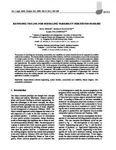
Figure 6 – Annotated diagram example (adapted from [2]).
The designer builds his/her diagrams through UML actions that add elements to the diagrams or change elements properties. These actions operate on two separate domains: the UML model, to which they add/change UML meta-model elements; and, the GEF graphical model, to which they add/change Fig nodes and/or edges. GEF node-port-edge graphical model provides two different types of commands for adding elements to the diagrams – CmdCreateNode for nodes, and CmdSetMode for edges –, for which the GEF architecture will get the renderer Fig and insert it in the model. In ArgoUML these simple commands are wrapped by actions that are added to the diagrams’ toolbar (see previous section). Adding new figs to the UML diagrams through this kind of actions is described in [4]. To annotate some element in a diagram, it is necessary one command to build the annotation node, and another to build the edge applying it to the element. Another characteristic of GEF commands is that they create empty UML model elements, e.g. a stereotype is created without a name.
RTClassDiagram RTClassDiagram() RTClassDiagram(in name : String,in m : Object) RTClassDiagram(in m : Object)
setNamespace(in handle : Object) : void getUmlActions() : Object[] getNewDiagramName() : String
ClassDiagramGraphModel
RTClassDiagramGraphModel canAddNode(in node : Object) : boolean addNode(in node : Object) : void
canAddEdge(in edge : Object) : boolean addEdge(in edge : Object) : void ClassDiagramRenderer
RTClassDiagramRenderer getFigNodeFor(in gm : GraphModel,in lay : Layer,in node : Object) : FigNode getFigEdgeFor(in gm : GraphModel,in lay : Layer,in edge : Object) : FigEdge
Nevertheless, another approach is possible. The actions that manipulate the diagrams can be made more complex, and add both node and edge figs. These actions derive from the UMLChangeAction class and do not wrap simple GEF commands, instead they interact directly with the GEF model and renderer. In terms of software architecture, the big difference between GEF commands and these actions, is that, in the former case, the rules that constrain the diagram construction are defined in the model (in the canAddNode(…) and canAddEdge(…) methods), while in the latter case, they are managed by the actions themselves (in their shouldBeEnabled() method). In functional terms, one single action can accomplish the full task of annotating a diagram element (see next section).
Figure 5 – Extending a ArgoUML Diagram.
When extending UML, it is good to remember that the standard language rules cannot be violated. The extended diagrams aimed to more specific domains can only augment the standard UML. Therefore, when deriving the classes of a standard diagram, the overriden methods must preserve their parents behaviour. For a different perspective about how to implement a new diagram in ArgoUML, see [7].
4. New Elements for the Diagrams This section discusses the possibilities that ArgoUML offers for adding new elements to UML diagrams, and justifies the proposed solution.
This leads to some important performance differences. Annotating a diagram element with GEF commands involves three user interventions (create an isolated empty node, choose a specific SPT annotation to fill it, and later link it to the element), whilst with UMLChangeAction actions only one user intervention is needed. Furthermore, with GEF commands, the UML-SPT meta-model rules that restrict the application of annotations to diagram elements, can only be verified at a late stage (the latest step, when the user is trying to link them), whereas actions can be enabled/disabled according to these rules before the
The implementation of SPT diagrams (with UML model elements annotated with SPT extensions) here described follows the guidelines and examples illustrated in [2], from which figure 6 is adapted. The SPT extensions (stereotypes, tagged values and constraints) are represented by UML notes connected to the annotated element through a dashed line. The stereotype name comes between guillemets (« ») or double angle-brackets (>), and the respective tagged values (pairs name = value) come as a coma (,) separated list enclosed in braces ({ }).
194
user makes a move.
· create the tags required by the stereotype, using the RTExtensionsFactory, and apply them to the target model element, through the ModelFacade; · create the GEF node (FigRTComment) to display the extension in textual form inside a note figure; · create the GEF edge (FigEdgeRTNote) to connect the target node (representing the model element being annotated) and the annotation node (representing the SPT extension) through a dashed line.
Consequently, actions achieve a more anticipated enforcement of the model syntactical correctness, are more efficient and more intuitive. Therefore, they are chosen to implement the addition of SPT annotations to the UML diagrams.
5. Adding SPT Extensions
ArgoUML core has several factories (see [11] for a description of the Abstract Factory pattern) named after the packages of UML meta-model, to create the respective elements. The factory for extension mechanisms elements (ExtensionMechanismsFactory class) does not allow the creation of stereotypes containing tags definitions. This is not compatible with the implementation the UML-SPT profile, not even with the UML 1.5 standard. It is necessary to have stereotypes with tag definitions, in order to create the corresponding tagged values and apply them to the model elements extended by the same stereotypes. For this purpose, the RTExtensionsFactory class is introduced.
This section describes the implementation of actions derived from UMLChangeAction that add SPT annotations (SPT stereotypes and tagged values) to extended UML diagrams. It also describes how the syntactical correctness of the annotations is assured. In terms of graphical tasks, these actions are similar to the core ArgoUML class for adding notes to UML diagrams (ActionAddNote class), since both have to create a GEF node to hold the annotation, and a GEF edge to make the connection between the annotation node and the node representing the model element to be annotated. In what concerns the changes to the UML model, they have to create the SPT extension (a stereotype and the respective tagged values) and apply it to the model element. This is accomplished by the ActionAddRTStereotype class in figure 7. To avoid dealing with the long list of extensions defined in [2], this action exemplifies the addition of a generic extension. diagramToolbar UMLDiagram
diagramToolbarActions JToolBar
+
The shouldBeEnabled() method of each action verifies the rules that enable/disable the respective button in the toolbar. More specifically, it returns true if the target’s meta-model class is one of the possible base classes to which the stereotype is applicable, and if it is not already extended by a stereotype with the same name. This way the UML designer gets a fundamental help in avoiding syntactic errors regarding the applicability of the UML-SPT extensions to the different model elements, and thus keeping the model correct from the early development stages.
TargetManager +
returnsActions 0..*
RTClassDiagram
0..*
UMLChangeAction
getInstance() : TargetManager getModelTarget() : Object +
+
getsTarget ActionAddRTStereotype ActionAddRTStereotype()
AbstractUmlModelFactory initialize(in o : Object) : void
6. Extensions Handling
actionPerformed(in ae : ActionEvent) : void shouldBeEnabled() : boolean +buildStereotype
RTExtensionsFactory
addTags
This section discusses how to provide an appropriate display for the UML-SPT tags, and an interface to edit their values in a manner that preserves the correct syntax. +
getInstance() : RTExtensionsFactory
In ArgoUML details panel (see [3] for a description of ArgoUML screen) there are several tabs that describe different aspects of the model. One of them (TabTaggedValues) is dedicated to the display and manipulation of the tagged values, in a double column table implemented with JFC/Swing table framework. Swing components are designed in a modified version of the Model-View-Controller paradigm (see [12]), in which the view and the controller are combined into an object called a delegate. In a Swing table framework the delegate is an instance of the JTable class, and the model is defined by the TableModel interface which is implemented by the AbstractTableModel class (see [13] for more details).
RTExtensionsFactory() buildStereotype(in me : Object,in name : String) : Object
ModelFacade
FigNodeModelElement FigEdgeModelElement
FigRTComment FigEdgeRTNote FigEdgeRTNote(in fromNode : Object,in toNode : Object)
Figure 7 – Adding a UML-SPT Stereotype.
Figure 7 illustrates also the other classes involved in the addition of the annotation. In a more detailed way the performed tasks are: · create a stereotype with a given SPT name (if not yet in the model) with its tag definitions and apply it to the target model element (represented by the diagram fig node selected at the moment), using the RTExtensionsFactory;
The table model in TabTaggedValues treats all cells
195
those characteristics.
as editable plain text, thus, they can have any text value, without restrictions. Besides, more tags can be added and existing tags can be removed.
The generic table presented, still needs to be tailored to handle properly the UML-SPT tagged values inside ArgoUML. More specifically, the RTTaggedValuesTableModel class makes the bridge between JFC/Swing table’s model and the UML model. The setTarget(…) method transfers the tagged values from the UML model to the table properties, and the setValueAt(…) is overridden to propagate the changes on the table properties to the tagged values in the UML model. To help with the translations between tagged values (UML model) and properties (GUI), an auxiliary class RTExtensionsProperties was introduced. It creates the Property objects for all the tagged values of the UML-SPT stereotypes.
This completely editable and dynamic table is an efficient and good looking solution. However, it is not optimized neither suitable for the UML-SPT tags, because they are predefined (in number and name) and they contain different types of values (boolean, enumerated, number and strings). Furthermore, it would be very important to syntactically validate their values. The previous section described how to ensure that the UML-SPT stereotypes are correctly applied to model elements, but the values of the respective tags have to be correct also. For example, if a tag is of boolean type, then it should be guaranteed that it only has the true/false values. Based on these considerations, it was necessary to implement another tab to display the tags for model elements annotated with UML-SPT extensions in a double column table with following requirements: · the first column is non editable and contains the tags’ names; · the second column contains the tags’ values, of different types of data, that should be editable in a syntactic correctness preserving manner; · it is not possible to add or remove tags.
ConfigLoader
JPanel
TabModelTarget TabSpawnable
TabTarget setTarget(in target : Object) getTarget() : Object refresh() : void
TabRTTaggedValues
shouldBeEnabled(in target : Object) : boolean TabRTTaggedValuesTable() resizeColumns() : void setTarget(in target : Object) : void
title
getTarget() : Object
JLabel
refresh() : void
JLabel()
shouldBeEnabled(in target : Object) : boolean
#
setText(in text : String) : void
scrollPane
targetAdded(in e : TargetEvent) : void JScrollPane
targetRemoved(in e : TargetEvent) : void
The JFC/Swing table framework provides functionalities that are very helpful in the implementation of a table verifying these properties. Swing’s tables have column oriented features like specifying/getting the type of data in a column for rendering/edition effects, and provide default cell views (renderers) and controllers (editors) for a predefined list of data types (the ‘How to Use Tables’ section in [9] gives further details). Nonetheless, this option is not valid to handle the UML-SPT tagged values, because in the same column different types of data coexist. One way around it is to provide views and controllers per cell, by overriding the JTable’s methods getCellRenderer(…) and getCellEditor(…).
+
targetSet(in e : TargetEvent) : void
JScrollPane()
JTable
#
+
tagsTable
displaysTags + DynamicPropertyTable
DynamicPropertyTable(in props : Property[],in nameCol : String,in valueCol : String) managesTags DynamicPropertyTable(in model : DynamicPropertyTableModel) getCellEditor(in row : int,in column : int) : TableCellEditor #
getCellRenderer(in row : int,in column : int) : TableCellRenderer
RTTaggedValuesTableModel
#
_model AbstractTableModel
RTTaggedValuesTableModel() setTarget(in t : Object) : void setValueAt(in value : Object,in row : int,in column : int) : void
DynamicPropertyTableModel managesProperties 0..*
RTExtensionsProperties
Property
Figure 8 – Tab for the UML-SPT Tagged Values.
A generic table was implemented, in order to cope with these constrictions. This table is constituted by a delegate of type DynamicPropertyTable, and an extensible model of type DynamicPropertyTableModel that manages a set of elements of type Property (see figure 8). The delegate class provides suitable renderers and editors, based on information provided by the Property class. It gets the default renderers and editors for the data types supported by Swing, and provides JComboBox editors with the appropriate SPT options for enumerated types, thus keeping the syntactic correctness of the model. The model is very simple and generic. It provides methods to add and remove properties, read and update the properties, and makes the first column non-editable. The Property class, that is part of the code in the CVS of ArgoUML project, defines a set of property characteristics (name, value, type…), and a set of methods to access
The tabs in the details panel are loaded by the ConfigLoader class, which reads the tabs’ class names from the file named ‘Argo.ini’ (complementary information can be found in [10]).
7. Conclusion This paper describes how the ArgoUML can be extended to implement the UML-SPT Profile. Some capabilities of its architecture are identified, and a few limitations are analyzed and worked around. The current ArgoUML API does not support pluggable toolbars and it is not possible to have the pluggable menus ordered. A description of how to overcome these issues, and provide a user-friendly interface, is given. The diagrams supporting the UMLSPT profile can be derived from the core ArgoUML
196
diagrams, thus resulting more simple. The different tasks for adding UML-SPT extensions should be grouped in a dedicated class, requiring only one user intervention, thus improving the tool’s efficiency. The current ArgoUML core does not allow the creation of stereotypes containing tag definitions, and consequently does not fully supports the UML specification. An abstract The implementation of such functionality is presented, to make possible the annotation of model elements with UML-SPT extensions. ArgoUML provides a tab panel which displays the tagged values without dictating any restrictions to their manipulation. Another tab panel with improved GUI is introduced, which handles the different tagged values with appropriate controls.
[4] L. Tolke & M. Klink, Cookbook for Developers of ArgoUML: An Introduction to Developing ArgoUML, revision 1.19. [5] S. Lopes & A. Tavares, Building a ArgoUML Module, ESRG Technical Report 04-01, University of Minho, Portugal, 2004. [6] Florent de Lamotte, Présentation d’ArgoUML, [cited September 2004]. [7] Florent de Lamotte, Ajout d’un diagramme à ArgoUML, [cited September 2004]. [8] Sun Microsystems, Inc., JAR File Specification, [cited September 2004]. [9] Sun Microsystems, Inc., Creating a GUI with JFC/Swing, [cited September 2004]. [10] Florent de Lamotte, Ajouter une nouvelle Tab dans le DetailsPane d’ArgoUML, [cited September 2004]. [11] E. Gamma, R. Helm, R. Johnson & J. Vlisides, Design Patterns: Elements of Reusable Object-Oriented Software (Reading, MA: Addison-Wesley Longman, 1995) [12] S. Burbeck, Applications Programming in Smalltalk80™: How to use Model-View-Controller (MVC), 19871992. [13] J. Zukowski, S. Stanchfield, Fundamentals of JFC/Swing: Part 2, MageLang Institute, April 1999.
The extension of ArgoUML is presented from the classes attaching to Argo to the last UI items, with a strong effort to systematize all the points necessary to implement a complete module. Hiding the ArgoUML internal details is a constant concern, and hence, an abstract and integrated perspective of the ArgoUML extension architecture is given. The solutions provided enforce the syntactic correctness of the SPT diagrams at design time. It was described how to guarantee that the stereotypes were applied to allowed base classes. Likewise, the table that handles the SPT tagged values ensures that their values are valid. Carrying out this error verification at design time is advantageous because it can decrease a project’s costs and significantly accelerate the development process. The UML-SPT is just a base for a more complete realtime profile, as stated in the standard itself. Having an open-source tool that implements it, is therefore a invaluable framework for the implementation and test of more refined profiles for that domain, and also for the study of different annotated UML diagrams to deal with other concepts and problems. ArgoUML exports the UML models in XMI format, which is also a door to innumerable analysis possibilities.
*
This work was supported by the “Fundação para a Ciência e a Tecnologia - PRAXIS XXI” program of the Ministério da Ciência e Tecnologia of the Portuguese Government.
References [1] Object Management Group, Unified Modeling Language Specification (UML), version 1.5, March 2003. [2] Object Management Group, UML™ Profile for Schedulability, Performance and Time Specification, version 1.0, September 2003. [3] M. Wulp, ArgoUML User Manual: A tutorial and reference description, revision 1.9.
197