Extending the UML for Designing Jack Agents Michael Papasimeon and Clint Heinze Air Operations Division Aeronautical and Maritime Research Laboratory (AMRL) Defence Science and Technology Organisation (DSTO) E-mail:
[email protected]
∗
April 19, 2001
Abstract Mainstreaming and industrialising agent technologies requires suitable methodological and technological support for the various engineering activities associated with managing the complexity of any software system development. Despite its origins in object oriented software engineering the UML provides a rich and extensible set of modelling constructs that can be applied to agent oriented technologies. This paper provides details of extensions to the UML for the design of agents that are to be implemented in the JACK language. These extensions provide the capacity to model the behaviour of agents for the purposes of design and, though the extensions are language specific, future generalisation and application to other agent languages can be supported as a industry-wide consensus about the nature of agency emerges over the next few years. This research builds on previously proposed extensions to the UML and moves a step closer to the goal of providing through-life engineering support to agent oriented systems development. This work is motivated by a pressing need to maintain, modify, develop and deploy existing and future agent based simulations of military operations for the Australian Defence Force.
1
Introduction
Although the Unified Modeling Language (UML) had its roots in the world of object oriented software, it has evolved into a general purpose graphical modeling language that can be used in the engineering of many different types of software systems. One of the advantages of the UML as compared to older object oriented design notations and methodologies is its capacity to accommodate the entire software development life-cycle. The language includes a rich set of diagram types and notation that allows the software engineer to model the system from requirements gathering, to analysis, architectural design, detailed design, implementation, testing, and deployment. The UML was designed to be extensible so that it could be tailored to suit not only different software design paradigms but to also support a specific domain. For example, to date the UML has been extended to deal with real-time systems, web based software, agents (see AUML), business and software process frameworks to name a few. The challenge of specifying, designing and implementing agent systems is made more difficult by the immaturity of the technology and the lack of specific methodological or tool support for agent languages. This paper presents a suite of extensions to the UML that can be used to specify, design, and implement a system that uses the JACK language1 . This work compliments previous work by Heinze, Papasimeon, and Goss [7] that extended the UML in the area of use cases and use case diagrams. This research is part of an ongoing effort to provide ∗ 506
Lorimer Street, Fishermans Bend, VIC 3207, Australia is an Australian developed Intelligent Agent language that implements a flexible agent reasoning framework as a series of extensions to JAVA. Further details about the language are available at the web site of Agent Oriented Software—www.agent-software.com.au 1 JACK
1
methodological and tool support for the construction of industrial multi-agent systems. This paper should be seen as a small component of this ongoing work. This work is motivated by the existence of large agent based simulations of air combat that are presently in operational use by the Australian Defence Force (ADF). To successfully manage the complexity associated with the future development, maintenance, and deployment of these systems a range of through-life software engineering tools and techniques are required. Specifically the JACK language is being evaluated as a candidate technology for the modelling and simulation of tactical decision making in the air combat domain [9]. Beyond a simple functional evaluation of the language the evaluation must also consider the ease with which JACK, or any agent language, can be integrated into existing software engineering processes. Obvious advantages are realised if the agent language can be easily integrated into the existing software engineering tools and processes. UML is a standard software engineering modelling language and when supported with tools such as Rational’s ROSE provides the basis for much of the organisations software development. The following section provides brief details about JACK followed by the extensions that have been added to the UML to support software design.
2
JACK
JACK (Java Agent Compiler and Kernel) is a JAVA based real time agent-oriented system that provides programming constructs for representing and implementing reasoning. It has its historical roots in the Belief-Desire-Intention (BDI) model developed by Rao and Georgeff [13] and is in that respect an advanced implementation of the Procedural Reasoning System (PRS) [6] developed by SRI International and thus has similarities with other BDI implementations such as dMARS and JAM. JACK is flexible enough to implement a variety of agent models with BDI being just one example. For the purposes of this paper JACK is considered only in its BDI form. The underlying theoretical model is described briefly here but detailed descriptions can be found in [13]. The interested reader can obtain information about dMARS in [5].
2.1
The Underlying BDI Theoretical Model
The logical foundations of BDI systems are based on the philosophical concepts of intentions, plans, and practical reasoning developed by Bratman [2]. Notions of practical reasoning, rational agency and beliefs, desires, and intentions themselves are based in good old fashioned folk psychology, Dennett [4] being an example of the formalising of folk psychology into a philosophical framework. BDI’s semantic model is based on a possible worlds branching-time tree structure. This model provides multiple possible worlds that represent the uncertainty in the world both now (due to limitations in perception) and into the future (due to dynamism). Each world includes a time tree with a single past and multiple futures. The multiple futures are dependant upon the action choices available to the agent. The beliefs, desires, and intentions of the agent are modal operators within this possible worlds semantics and are represented with a combination of modal logic and computational tree logic. The beliefs of an agent are its view as to the state of the environment. This view does not necessarily accurately reflect the actual world and is subject to uncertainty, error, distortion, or limitations in perception. The desires of an agent are those states of the environment that an agent would wish to attain. An assumption of rationality implies that an agent will maintain only desires that are believed to be achievable and are mutually consistent. This subset of possible desires is often referred to as goals. An intention is a commitment by an agent to achieve a goal. This commitment implies that the agent will endeavour, through whatever means are available to it, to arrive at the ends defined by that goal. The particular means available to an agent is a function both of the type of BDI implementation and the specific nature of the constructed agent. For example, the JACK implementation of the BDI model includes the notion of plans as specifications of means–ends reasoning or recipes [12]. Thus a JACK agent utilises plans as the means by which behaviour is realised. By adding an operational semantics associated with plans that is consistent with notions of bounded or resource limited rationality a family of BDI systems that can operate in dynamic, volatile, or real-time environments can be constructed. These agents implement a form of
2
reasoning where behaviours are pre-planned sequences of goals to be achieved and actions to taken. Thus plans provide an abstract specification for the achievement of a goal through the decomposition of that activity into sub-goals and their related sub-plans. By committing to a plan only when a sub-goal is reached the agent implements a least-commitment style of decision making that is appropriate for dynamic real-time systems. The BDI model has proven to be a good one for modelling intelligent behaviour in rapidly changing worlds. In part this is due to the power of the underlying concepts in dealing with the complexities of the reasoning behaviour and also the folk-psychological familiarity achieved through implementing everyday concepts such as beliefs, desires, and intentions [8].
2.2
The Components of a JACK Agent
A JACK agent is a computational implementation of the above BDI model and as such it provides a reasoning framework with a specific set of language constructs. These constructs are just one possible implementation of the BDI model but provide the programmer with a modeling framework that is a mix of the high-level representational abstraction of the BDI model and the low level detail of the JAVA language. This paper will concentrate on the modeling of the specific high level agent concepts and ignore the modeling of the JAVA aspects of JACK programming2 . The following section lists and briefly describes the major components of a JACK agent that need to be considered at design time. Further details of the operational semantics is available [3] or the detail of the implementation [10]. AGENT The agent is the primary entity within the BDI model and is implemented within JACK as an autonomous module composed of capabilities, plans, databases, and events. Agents can address other agents and post events to them thus modelling inter-agent communication. DATABASE The Database is the JACK implementation of the beliefs of the agent. These represent the agents view of the world as first order relational statements that are maintained as consistent through the specification of constraining key fields. EVENT Events are those things that an agent responds to. They arise internally to an agent as reasoning progresses, as a result in a change in the agents beliefs, or on receipt of a communication from another agent. PLAN A plan is a specification of a sequence of actions to undertake in response to an event. The plan contains a #handles event declaration that defines the event that the plan is suitable for. The system selects from amongst a number of suitable plans through examination of the context. The context method defines in detail the exact agent states under which the plan is applicable. The main part of the plan is its body. The body is a function that can mix standard JAVA code with Jack Agent Language (JAL) statements that can alter the agents beliefs, post new events, or send messages. From a design perspective the plans are the modular procedures that provide the building blocks for specifying the behvaiour of the agent. CAPABILITY Capabilities are sets of plans, events, and databases that are functionally grouped to provide a specific capability to an agent. These high level programming constructs are accompanied in JACK by many specific concepts that define the syntax of the JAL. Whilst some of these concepts are mentioned in later sections a detailed account of their operation is beyond this paper. Further details about the JAL is available [10].
3
Stereotypes: The UML Extension Mechanism
The main UML extension mechanism is that of the stereotype. A stereotype can be considered as a label that is applied to a UML modeling element that changes the meaning of the element to a definition specified by the domain in which the stereotype is applied in. A UML stereotype is indicated by placing the name in double angled brackets ( ), 2 The modelling of standard JAVA programs with the UML is a routine software engineering endeavour. The links with the JACK language add complexities but these will be examined in a later paper.
3
and can be applied to any UML element including classes, associations, use cases, attributes, and methods. For example, if we wanted to model enumerated types which are supported by languages such as C++, and we wanted to make them visible at the design level we could define an stereotype. This would usually be defined in a corporate, community or domain design standard with precise syntax and semantics and examples of how to translate the design into code for the required language. This would allow the designer to specify in a UML tool a common enumeration of different types of colours as shown in the Figure 3. Here, a class construct has been stereotyped with the stereotype. The stereotype definition in say a corporate design standard would then allow the programmer to look at this design and implement the following C++ code.
Colour + Red + Orange + Yellow + Green + Blue + Violet
typedef enum { Red, Orange, Yellow, Green, Blue, Violet } Colour;
Figure 1: UML Enumeration Stereotype and Corresponding C++ Code In addition to specifying a stereotype using angled brackets, most modern UML tools also allow specific icons to be used in place of the standard object oriented notation. This allows a particular software development community (real-time, agent oriented, web) to develop a diagrammatic notation that is tailored to their needs, but at the same time is completely compliant with the UML, as long as the stereotypes are well defined and publicly available for other software engineers to use. Examples of stereotype icons which are part of the core UML are shown in Figure 3. The figure also shows that specific stereotypes can be replaced by icons as is the and stereotypes represented by a stick figure and a small circle respectively.
Pilot
Radar Model
Pilot
+ Init() + Com pute() + Close()
Radar
Model + Init() + Compute() + Close()
Figure 2: Examples of UML Stereotypes
4
Jack Extensions to the UML
Work in extending the UML to accommodate agent oriented systems such as the AUML [1], has to date concentrated on high level architectural issues such as communication protocols between multiple agents. To date, there haven’t been any extensions that will allow a software engineer to design an agent oriented system with UML down to the detailed design level. This is partly due to the fact that agents are a relatively young technology and there hasn’t been any dominant agent languages (such as C++, Java, Python and Eiffel in the OO world) that have a large enough user base to influence international standards such as the UML. UML can be extended to accommodate Jack specific constructs through the definition of some Jack specific stereotypes. Although the stereotypes can be generalised to allow the modeling of
4
any BDI based agent system using UML, in this paper the focus is on Jack. Generalisations will be looked at a later date. Due to the fact that Jack is built on top of an object oriented foundation in Java, extending UML to handle Jack is quite easy. Although it is possible to extend UML to accommodate a BDI language such as dMARS it requires a bit more work than the Jack case. So what type of stereotypes do we need to add to the UML so that we can design Jack agents before getting into the code? The stereotypes required fall into a number of general categories. High Level Jack Constructs - we require stereotypes to describe high level Jack modeling components such as an agent, plan, database, event and capability. Associations - we need stereotypes to describe the special Jack relationships between plans, events, databases etc. Low Level Constructs - we need some stereotypes to handle low level Jack constructs such as database fields, reasoning methods etc. Once these stereotypes have been defined a mapping between the UML notation and Jack code can be built. This mapping can then be used by the detail designer or programmer to progress the agent system from architectural design, to detailed design and eventually to code.
4.1
High Level Stereotypes
High level constructs in Jack include agent, plan, database, event and capability. Since a capability is used to group functionally related agents, plans, databases and events, a stereotype can be defined for UML packages. In object oriented applications UML packages are usually used to group functionally related classes into packages, subsystems or modules. In addition to Jack specific constructs – agents, plans, databases and events can have attributes and methods just like any other Java class. Hence, it make sense to define class level stereotypes for these Jack constructs as defined in Table 1, with examples in Figure 4.1.
Stereotype
Description Class level stereotype that defines a Jack agent. Class level stereotype that defines a Jack plan. Class level stereotype that defines a Jack database. Class level stereotype that defines a Jack event. Package/Subsystem level stereotype defining a Jack capability. Table 1: High Level UML Stereotypes for Jack
Navigator
Position
LaunchWeapon
Electronic Warfare
ReceivedRadioMessage
Figure 3: Example of Stereotyped Class/Package Level Elements in UML
4.2
Association Level Stereotypes
When building Jack agents, developing a set of plans, events and databases isn’t enough to define the behaviour of an agent. We need to show how these entities are related to each
5
other. For example, we need to know which plans and databases are used by what agents, which plans handle specific events and what databases plans can modify. In UML uni-directional associations can be used to define relationships between agents, plans, databases and events. A set of stereotypes defined in Table 2 can be used to label these associations according to specific type of Jack relationship that needs to be represented. An example of how the association stereotypes are use is shown in Figure 4.2.
Stereotype
Description Indicates a database posting an event. Indicates an agent using a plan. Indicates a database which a plan can modify. Indicates an event handled by a plan. Indicates a private database owned by an agent. Indicates a plan using an agent implementing an interface.
Table 2: Association Level UML Stereotypes for Jack
INavigator
Navigator
Position
FlyWaypoint
Moved
Figure 4: Partial Design for a Model of an Aircraft Navigator with Jack/UML
4.3
Low Level Stereotypes
In addition to the class/package and association level stereotypes, some stereotypes at the attribute and method level are also required. For example, fields specified in Jack databases need to be distinguished between key and value fields. Attribute level and stereotypes are defined to achieve this distinction. Similarly in Jack plans, the ability to distinguish between regular Java methods and Jack reasoning methods (where special Jack commands can be used) is required. Again, we can define a method level stereotype that can be used to decorate a method to distinguish it from a regular Java method. A non exhaustive list of attribute and method level stereotypes is shown in Table 3. Figure 4.3 shows examples of attribute and method level Jack stereotypes.
4.4
Putting It All Together
Using the Jack specific UML stereotypes allows the programmer to design Jack agents with a industry standard graphical notation. Without such an ability the Jack programmer or software engineer would be forced to by pass important and valuable software engineering life cycle stages of architectural and detailed design and jump directly to coding, or be forced to invent a notation. Figure 6 shows a design of a simple Jack agent in UML. The agent represents a model of Surface To Air Missile (SAM) Commander for use in a military simulation. The
6
Stereotype
Description Attribute level stereotype indicating a key field in a database. Attribute level stereotype indicating a value field in a database. Method level stereotype indicating an indexed query in a database. Method level stereotype indicating how an event gets posted. Method level stereotype to indicate a reasoning method in a plan.
Table 3: Association Level UML Stereotypes for Jack ClosedWorld
DestroyThreat - threatLocation : Position + relevant() + context() + body() + FindLauncher()
FactorialDb - value : int - factorial : long
NewTrack - trackId : int
+ get(v : int, f : logical long) + get(v : logical int, f : logical long)
+ NewTrack()
Figure 5: Examples of Jack Elements Using Attribute and Method Level Stereotypes
Commander has a belief database about the tracks he/she detects on an acquisition radar. Based on this information, events can be posted each time a new track is identified or when an existing track is classified as hostile. In this example we can see that the SAM Commander agent has two plans (one to identify a track and another to destroy a threat) that can respond to these events.
4.5
From Detailed Design to Code
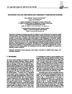
With the specification of UML stereotypes that correspond to specific Jack constructs, it is possible for a Jack programmer to produce Jack code from the UML diagrams. What this means is that using these diagrams allows the programmer to directly code up the Jack and Java stubs either manually or automatically. A manual translation would simply involve the programmer using the diagram together with knowledge of Java, Jack and a document describing the mapping between the UML Jack stereotypes and Jack code. Alternatively, many modern UML CASE tools are open and extensible giving the engineer access to the underlying UML (including stereotyped elements) via a scripting language. For example CASE tools like Rational Rose via RoseScript (a Visual Basic for Applications variant) and Object Domain via Python provide access to the UML model and allow document and code generation scripts to be written. The Jack designs presented in UML (as in Figure 6) show the overall structure (or architecture) of a particular agent but don’t allow for the specification of the agent’s internal behaviour as defined by the agent’s set of plans. For each plan (or method), most UML CASE tools allow the engineer to document the intended behaviour using informal textual descriptions which can then be either generated as part of the system documentation or be generated in code comments to provide a local reference to the programmer whose job is to actually implement the underlying algorithms. An alternative to using informal text to specify plan behaviour, is to associate either a state chart or an activity diagram with a particular plan, an example of which is shown in Figure 7. The advantage to using an activity diagram is that it provides a graphical notation to describe the behaviour of a particular plan. This will be familiar to dMARS programmers which used a graphical flowchart type language (in conjunction with formal LISP like semantics) to define the behaviour in a plan.
7
AcquisitionRadarTracks < < k e y field>> trackid : int < < value field>> latitude : float < < value field>> longitude : float < < value field>> altitude : float < < value field>> hostile : boolean < < value field>> handled : boolean
SamCommander Init() : void Compute() : void C l os e ( ) : void S a m C om m a n d e r ( n a m e : s t r i n g ) : void < < s y n c h r o n i z e d > > A d d L a u n c h M i s s i l e C o m m and() : void < < s y n c h r o n i z e d > > A d d T r a c k T a r g e t C o m m and() : void
+radarTracks()
GetTrack()
IdentifyTrack
body()
SamCommanderInterface
+newTrack
NewTrack trackid : long
Init() : void C o m p u t e () : vo id C l os e ( ) : void A d d L a u n c h M i s s i l e C o m m a n d ( ) : void A d d T r a c k T a r g e t C o m m a n d ( ) : void
+newTrack
newtrack()
< < E vent>> HostileTrack trackid : long latitude : float longitude : float altitude : float hostiletrack()
DestroyThreat id : long latitude : float longitude : float altitude : float launcher : String
r e l e va n t () context() b o d y () getLaunchSite()
Figure 6: Design of a SAM Commander Model in Jack/UML
5
Mapping Agent Languages to UML
When designing object oriented software with UML, it is possible for the engineer to postpone annotating the diagrams with language specific constructs until quite late in the design process. This usually happens in the final stages of detailed design when the engineer is ready to generate code from a CASE tool. At this stage of the detailed design and implementation process, it is common to either annotate the diagrams or (through some other mechanism in the CASE tool) add language specific (C++, Java, Python, Eiffel, etc) constructs to assist in the code generation process. If a CASE tool isn’t to be used to generate code, the object oriented UML design can usually be kept implementation language independent. There are a number of reasons why this is possible. Firstly, there are many similarities between most object oriented languages. Secondly, UML (and it’s ancestors) were heavily influenced by the requirements of practitioners who have been using popular object oriented languages such as C++ and Java. Unfortunately for agent practitioners, since most agent languages are relatively new technologies they are not as in widespread use as object oriented languages, and hence specific extensions to the UML are required. Furthermore, since there is no agreed upon standard definition on what types of properties an agent language should have, there is a great variation in the range of agent languages available. As a result of this variation, trying to come up with a generic agent oriented design notation becomes increasingly difficult because a solution which is very language specific results, as in the case of extending the UML to accomodate Jack, The work of James Odell and others with Agent UML (AUML) [11], extends UML for the design of agent systems. However it primarily deals with issues such as inter-agent communication and provides little in the way of specifying the internal design or structure of an agent. The use of state charts and activity diagrams (as discussed in the previous section with regard to plans) to describe the internal behaviour of agents is also proposed by the AUML. The main difference is that whereas the AUML suggests that an agent’s behaviour can be specified with an activity diagram, following on from the BDI model used in Jack, it is preferable to have an activity diagram per plan used by a particular agent. This is because BDI agents
8
Start
Assess Track
[ assessment is not hostile ]
End1
[ assessment is hostile ] Find Valid Launchers
[ no more valid launchers ]
End2
[ more valid launchers ]
Issue Track Target Command
Figure 7: Plan Behaviour Specification with a UML activity diagram
may have hundreds or even thousands of plans to deal with different contexts and situations that can arise in a complex environment such as in a model of the air combat domain. What the AUML to date doesn’t provide is a mechanism for specifying the internal design or structure of an agent. That is, the relationships between the agent and its belief databases, plans, events and how they are grouped into capabilities. The Jack stereotypes and notation presented in the previous sections allow you to do this, albeit with language specific constructs. In the longer term, it would be preferable to move away from UML stereotypes that are language specific. The next logical step would be to look at a family of agent languages all implementing a similar model. For example, an analysis of the BDI model and the BDI family of agent languages (PRS, dMARS, JAM, Jack), would produce a set of modelling concepts that capture the essence of the BDI model and are common to the family of languages. It would then be a matter representing these concepts in UML through it’s extension mechanisms such as stereotypes. A set of mappings between the UML representation and the individual languages will also need to be produced. This would then allow the agent-oriented software engineer to design a BDI agent in UML without necessarily worrying about the implementation language until the detailed design or implementation phases of development.
6
Conclusions
One of the UML’s most powerful features is its ability to be extended through constructs like user defined stereotypes. This extension mechanism allows the one modeling language to be used to model and design a wide range of software systems by tailoring the language to a particular domain or to a particular type of software technology. Today, UML extensions have been defined for online web applications, databases, XML, real-time systems, business modelling, enterprise computing, software development processes and agent oriented systems among others [14]. The stereotypes and notation presented here which extend the UML for designing Jack agents has a number of advantages. Firstly, it provides a standard industry accepted notation for designing systems for a language which by no means is broad and general purpose, but is meant for niche applications. This is an example of how a common modeling language can be used to model systems using a wide range of software technologies. Secondly, an agreed upon notation encourages the Jack programmer to go through the formal process of developing an architectural and detailed design in UML before beginning to code. Finally, there is an existing set of diagramming and CASE tools that can be used out of the box to design Jack agents. Effort in building custom, language specific tools or integrated development environments is greatly reduced, as activities such as code generators can be added to existing tools.
9
The main drawback to defining language specific extensions to UML is exactly that – the extensions are specific to a particular language. The main problem with this is that you have often have to start dealing with language specific constructs much earlier in the design process than usually required for say, object oriented modeling and analysis. It is obvious that the next logical step would be to generalise the extensions presented here to accommodate the family of BDI languages. Following this, a set of extensions for all types of agents would be ideal but possibly not practical due to the large differences between different types of agents. The fact that agent technology is still young and maturing, and also that there are no dominant agent languages available, it may be that a set of different extensions to UML will be developed for the different types of agents (information agents such as web-crawlers, rational agents such as the BDI variant, e-commerce agents). The path agent technology takes over the next few years and industry consensus will ultimately determine what set of UML extensions are finally adopted for the design of agent systems.
References [1] Bernhard Bauer, Jrg P. Mller, and James Odell. Agent UML: A formalism for specifying multiagent interaction. In Paolo Ciancarini and Michael Wooldridge, editors, AgentOriented Software Engineering, pages 91–103, Berlin, 2001. Springer-Verlag. [2] M. E. Bratman. Intentions, Plans, and Practical Reason. Harvard University Press, Cambridge, MA, 1987. [3] Paolo Busetta, Ralph Ronnquist, Andrew Hodgson, and Andrew Lucas. Jack intelligent agents—components for inteliigent agents in java. User Manual 1, Agent Oriented Software, Melbourne, Australia, March 2001. [4] D. C. Dennet. The Intentional Stance. MIT Press, sixth edition, 1987. [5] M. d’Inverno, D. Kinny, M. Luck, and M. Wooldridge. A formal specification of dmars. In Singh, Rao, and Wooldridge, editors, Intelligent Agents IV: Proceedings of the Fourth International Workshop on Agent Theories, Architectures and Languages. Springer Verlag, 1998. [6] M. P. Georgeff and A. L. Lansky. Procedural knowledge. In Proceedings of the IEEE Special Issue on Knowledge Representation, volume 74, pages 1383–1398, 1986. [7] C. Heinze, M. Papasimeon, and S. Goss. Specifying agent behaviour with use cases. In Proceedings of Pacific Rim Workshop on Multi-Agents, PRIMA2000, 2000. [8] C. Heinze, Brad Smith, and M. Cross. Thinking quickly: Agents for modeling air warfare. In Proceedings of 4th Australian Joint Conference on Artificial Intelligence. AI’98, 1998. [9] Andrew Lucas and Simon Goss. The potential for intelligent software agents in defence simulation. Technical Report 2, Agent Oriented Software, Melbourne, Australia, March 2001. [10] Paul Maisano. Jack user guide. User Manual 3.1, Agent Oriented Software, Melbourne, Australia, March 2001. [11] James Odell, H. Van Dyke Parunak, and Bernhard Bauer. Extending UML for Agents. In Proceedings of AOIS Workshop at AAAI, 2000. [12] A. S. Rao. A unified view of plans as recipes. In G. Holmstrom-Hintikka and R. Tuomela, editors, Contemporary Action Theory. Kluwer Academic Publishers, The Netherlands, 1997. To appear in late 1997. [13] A. S. Rao and M. P. Georgeff. Modeling rational agents within a BDI-architecture. In J. Allen, R. Fikes, and E. Sandewall, editors, Proceedings of the Second International Conference on Principles of Knowledge Representation and Reasoning, pages 473–484. Morgan Kaufmann Publishers, San Mateo, CA, 1991. [14] James Rumbaugh. Trends in UML and e-development. The Rational Edge, December 2000. http://www.therationaledge.com/content/dec_00/f_uml.html.
10