Proc. VIIth Digital Image Computing: Techniques and Applications, Sun C., Talbot H., Ourselin S. and Adriaansen T. (Eds.), 10-12 Dec. 2003, Sydney
Fast Adaptive Algorithm for Time-Critical Color Quantization Application K. Kanjanawanishkul1 and B. Uyyanonvara2 1,2
Department of Information Technology Sirindhorn International Institute of Technology (SIIT), Thammasat University 131 Moo 5, Tiwanont Rd. Bangkadi, Muang Pathumthani 12000, Thailand
[email protected] [email protected]
Abstract. Color quantization is the process of grouping n data points to k cluster. We proposed a new approach, based on Wu’s color quantization [6]. Our approach can significantly reduce the time consumption during the process compared with available methods but still maintain an acceptable quality of color distribution. As a rough rule of thumb [4], a quantized image with more than 30 dB of PSNR is often indistinguishable from the uncompressed original image. To achieve this requirement, we proposed to put the cutting plane through the centroid of the largest value representing variance box on the 3Dcolor histogram of color distribution. This plane is perpendicular to the axis, on which the sum of the squared Euclidean distances between the centroid of both sub-boxes and the centroid of the box is greatest. This guarantees that the total variances of sub-boxes are reduced automatically. To speed up the process, we exploited the dynamic programming as Wu [6] used in his approach. Unlike Wu’s approach, we replaced the second order moment calculation with a value representing variance. Because variance is not actually used in calculation, a simpler indicator of data scatterness would speed up the process. From our whole process, we achieved approximately 40% less time consumption than Wu's quantizer [6].
1 Introduction Although a full color system using 8-bit of each component (Red, Green and Blue) is commonly used now to specify the color of each pixel on the screen, color quantization is still a powerful method for color image size reduction. The quantizer converts the 24-bit/pixel color image into the 8-bit indexed color with a set of representative colors (256 typically). Therefore, the size of the quantized image is 3 times reduced. This makes the color quantization process be fluently exploited for many applications especially in computer graphics and image processing.
781
Proc. VIIth Digital Image Computing: Techniques and Applications, Sun C., Talbot H., Ourselin S. and Adriaansen T. (Eds.), 10-12 Dec. 2003, Sydney
This paper was organized as follows. In Section 2, we introduced the literature survey of color quantization. We explained our proposed approach in Section 3. Experimental results were introduced in Section 4. Finally, we concluded and gave some future works in Section 5.
2 Literature Survey Over the past decade, there are a large number of approaches. Some proposed to adapt the excellent techniques such as neural network or fuzzy-logic to their quantizers. However, the entire process consists of compression and decompression. Schrader and Wittgruber [17] proposed the interesting method to reduce the runtime of visualization or decompression on CLUT devices. For our application, we emphasized in the runtime of compression process only and then those compressed streams are transferred to the external display device, i.e. LED display board. Generally, color image quantization can be separated into two steps for the compression algorithm i.e. palette design and pixel mapping. The first step involves the design of a palette in which a subset is chosen from the true color space. In the second step, input pixels of the original image are mapped to colors from the palette.
2.1 Palette Design There are two general classes of quantization methods: fixed or universal palette and adaptive or custom palette. For fixed quantization, it is independent from the image contents, while for the adaptive quantization, a palette is designed adaptively to the image contents. The existing adaptive techniques to design a color palette can be divided into three categories [8]. a) Hierarchical scheme or pre-clustering: Most of the proposed algorithms are based on statistical analysis of the color distribution of image pixels within the color space. The popularity [1], median cut [1], variance minimization [2], Octree [5] and Principal Analysis Algorithm [6] are all examples of this scheme. b) Iterative scheme or Post-clustering: It involves an initial selection of a palette followed by iterative refinement of this palette using the K-Means algorithm [7] to minimize the Mean Square Error. Fuzzy C-mean [9] is an extension of the K-means algorithm [7]. The Hierarchy Competitive Learning (HCL) [10], Genetic C-means Algorithm (GCMA) [11] and NeuQuant [13], exploiting the Kohonen SelfOrganizing-Maps [12] are all examples of this scheme. Two more hybrid methods are Local K-Means (LKM) [15] and Adaptive Color Reduction (ACR) [16]. LKM combined a K-Means quantization and Self-Organizing Map, while ACR consists of a principal component analyzer and a Kohonen Self-Organizing Feature Map (SOFM). c) Improved scalar quantization: There is a group of very simple algorithm which can be classified as based on improved scalar quantization rather than on vector quantization. Sequential scalar quantization [14] is an example of this scheme.
782
Proc. VIIth Digital Image Computing: Techniques and Applications, Sun C., Talbot H., Ourselin S. and Adriaansen T. (Eds.), 10-12 Dec. 2003, Sydney
2.2 Pixel Mapping After obtaining the color palette, the next step is to map each input pixel in the image to a color in the palette. a) Brute-force algorithm: The straightforward way to find the best mapping. b) k-d Trees: The classical k-d tree method for nearest-neighbor search by orthogonal partitioning was proposed by Friedman [3]. c) Locally Sorted Search: the locally sorted search technique was proposed by Heckbert [1]. It shows the greatest advantage over brute-force algorithm when the number of representative colors is large and when the colors in the input image have a wide distribution. d) Centroid Mapping: A faster, sub-optimal alternative to nearest-representative mapping is to use the partition obtained during the color palette design process and map the image colors to the representative, which is the centroid of the cluster containing the color.
3 Our Proposed Techniques Clearly, a large number of papers proved that the hierarchical method is faster than the iterative method but it gives less quality than the latter. However, the hierarchical scheme cannot correct later for erroneous decisions made earlier. Since our target is to design a new quantizer for the time-critical applications. We thus proposed a new approach, which belongs to the hierarchical scheme. We exploited the dynamic programming according to Wu’s algorithm [6] proposed in 1992. His quantizer outperforms the early quantizers with respects to both computation time and quantization quality and is still mentioned in many papers now. Thus we also used Wu’s quantizer for comparison purpose. Our approach presented in Subsection 3.1 can reduce the computational time with an acceptable quality. The quality metric was also investigated in order to point out the performance of the quantizers in Subsection 3.2.
3.1 Our Techniques for Color Quantization We separated the whole process of the color quantization into four phases according to Wu's approach; i.e. a) Histogram construction; b) Cumulative Moment Construction; c) Cutting Plane Positioning and d) Pixel Mapping. a) Histogram Construction Phase It is impractical to use the 24-bit/pixel resolution to construct the 3D histogram because 28x28x28 or 16,777,216 bytes of memories have to be allocated. Thus, we started with the same way as Heckbert’s approach [1]. A 25x25x25 or 32x32x32 color histogram, created from a 24-bit per pixel-color image by reducing the resolution of each color component to 5 bits, was processed first. Although a 32x32x32 3D histogram was employed, the human eyes cannot distinguish the pre-quantized image.
783
Proc. VIIth Digital Image Computing: Techniques and Applications, Sun C., Talbot H., Ourselin S. and Adriaansen T. (Eds.), 10-12 Dec. 2003, Sydney
However the time consumption of this phase rather depends on the size of an input image. b) Cumulative Moment Construction Phase In this phase, the dynamic programming was exploited in order to avoid recomputation of the value of mean and our value representing variance when positioning the cutting plane on the 3D-color histogram. We used Wu’s algorithm [6] to construct the bottom-up dynamic programming after 3D-color histogram was obtained. Unlike Wu’s algorithm [6], we eliminated this second-order moment distribution, which was employ to calculate the variance, because it produces the very high execution time. A value representing variance, mentioned in the next paragraph, was used instead of the actual variance. This value was investigated from the zerothorder moment which cumulate the frequency and the first-order moment which cumulate the frequency multiplied by its pixel value. Furthermore the point of which weight was less than 5, was ignored because of reduction of the discrepancy of this value representing variance. After we have already got the zero-order and first-order cumulative distribution, we can obtain the centroid of each box by using the summation and subtraction as defined in Equation (1). Frequency[r 0 to r1, g 0 to g1, b0 to b1] = Freq[ r1, g1, b1] − Freq[ r 0, g1, b1] − Freq[ r1, g 0, b1] − Freq[r1, g1, b0]
(1)
− Freq[ r 0, g 0, b0] + Freq[ r 0, g 0, b1] + Freq[ r 0, g1, b0] + Freq[ r1, g 0, b0] Sum of Red[ r 0 to r1, g 0 to g1, b0 to b1] =
R[r1, g1, b1] − R[r 0, g1, b1]
− R[r1, g 0, b1] − R[r1, g1, b0] − R[r 0, g 0, b0] + R[r 0, g 0, b1] + R[r 0, g1, b 0] + R[r1, g 0, b 0]
Therefore, Mean of Red =
Sum of Red [ r 0 to r1, g 0 to g1, b0 to b1] Frequency [ r 0 to r1, g 0 to g1, b0 to b1]
where R[ ] is the cumulative Red pixels to that point (first-order moment of Red axis) Green and blue are also calculated in the same way. c) Cutting-Plane Positioning Phase The main difference among the other proposed approaches was how to position the cutting plane, which gives the optimal result. For our approach, we want to reduce the time consumption as much as possible while the PSNR, which we use as a criterion, should be more than 30-dB or in the other word, Mean Square Error should be less than 195. In this section, we showed that it does not need to use the multiple cutting planes to find the minimization of variance. We can put the cutting plane passing the centroid of the box to be perpendicular to the coordinate axis. Although, it does not obtain the best position, the quality is still acceptable as displayed in the results. However, it does not satisfy us in terms of time consumption, we proposed a value representing variance as mentioned earlier instead of the actual variance which requires the high computational cost. First of all, we evaluated the centroid of one box, which enclosed the colors of all pixels from the original image. After that we put the
784
Proc. VIIth Digital Image Computing: Techniques and Applications, Sun C., Talbot H., Ourselin S. and Adriaansen T. (Eds.), 10-12 Dec. 2003, Sydney
three planes to be perpendicular to red-axis, green-axis and blue-axis. Consequently, eight sub-boxes were obtained. Then each centroid of these sub-boxes was calculated. These centroids were used as the representatives of the data in each sub-box. Equation (2) shows the value representing variance of the box. 8
Value Representi ng Variance =
∑ || X
(2)
_
i
− X ||
i =1
where || || stands for the Euclidean distance norm X i is the centroid of each sub - box X is the centroid of the box This formula was also performed to find the largest value representing variance of the available divided box. The next step was to find the axis to be perpendicular. Clearly, that axis, which gives us the minimization of the sum of MSE of both divided boxes, should be selected. This guaranteed that the overall MSE was reduced automatically. Although MSE of total sub-divided boxes is greater than Wu's quantizer [6], it is still acceptable. We split this box at the centroid to be perpendicular to Redaxis first. The centroid of each sub-box was obtained by using Equation (1) and then we calculated the sum of the squared Euclidean distances between the centroid of both sub-boxes and the centroid of the box. The squared Euclidean distance was defined in Equation (3). (3 )
P
d SQEC (X1, X 2 ) =
∑ (x
1j
− x2 j ) 2
j =1
We exploited this distance for comparison among three axes. Equation (4) was evaluated for Red-Axis, and there we got the cutting plane, which was perpendicular to Red-Axis passing through the centroid of the box. Green and blue also were performed in the same way. _
_
_
_
_
Squared EuclideanDistanceof Red = f1(r1 − r)2 + f1(g1 − g)2 + f1(b1 − b)2 +
(4)
_
f2(r2 − r)2 + f2 (g2 − g)2 + f2(b2 − b)2 _ _ _
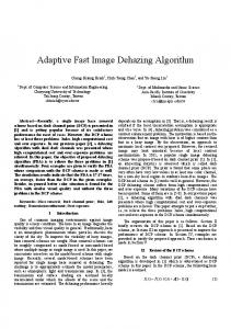
where r , g, b is the centroid point of the box r1 , g1 , b1 is the centroid point of the lower box r2 , g 2 , b 2 is the centroid point of the upper box f1and f 2 are the number of the pixels in the lower box and upper box divided by f1 + f 2 respectively The largest summation among three axes of the squared Euclidean distance means that the upper box and the lower box clusters are dissimilar. Therefore, it should be separated into two boxes orthogonally on that axis. Figure 1 showed an example of the automatic reduction of total MSE of a resulting image. This tree guaranteed that the global MSE of the quantized image was reduced although this method cannot find the optimal cutting position. Certainly, Red-axis was
781
Proc. VIIth Digital Image Computing: Techniques and Applications, Sun C., Talbot H., Ourselin S. and Adriaansen T. (Eds.), 10-12 Dec. 2003, Sydney
selected because it produced less MSE than the others and its squared Euclidean distance was the largest. 3D-Color Histogram MSE: 9169.15 Value representing Variance: 314.617
Red-Axis
MSE: 5292.534 Distance: 60.938
Green-Axis
MSE: 5472.504 Distance: 58.486
Blue-Axis
MSE: 6499.323 Distance: 41.988
Fig. 1. Variance Reduction Tree on “Mandrill” standard image
d) Pixel Mapping Phase This was the final phase, we used the same algorithm as Wu’s quantizer [6], that is, the centroid mapping. The centroid mapping is very fast. It maps every color, which belong to that box, to its centroid. It is effective when the number of colors in the original image is smaller than the number of pixels in the image. Since the prequantization to 15 bits is used, the number of colors will be under 32768.
3.2 Quality Measures In fact, there is no good objective criterion available for measuring the perceived image similarity. However, there are a number of common error measurements, used in the color quantization community, i.e. Mean Squared Error (MSE) and Peak Signalto-Noise Ratio (PSNR). Peak Signal to Noise Ratio or PSNR measures the amount of useful data versus the amount of noise introduced into the image. Therefore, the higher the number, the more accurate the reconstruction. Below is the formula of PSNR calculation. PSNR = 10 * log(
Max ( original image ) 2 ) MSE
(5 )
As a rough rule of thumb [4], above around 30 dB images look pretty good and are often indistinguishable form the uncompressed original image. PSNR is a good measure for comparing restoration results for the same image, but between-image comparisons of PSNR are meaningless. One image with 30 dB PSNR may look much better another image with 30 dB PSNR.
781
Proc. VIIth Digital Image Computing: Techniques and Applications, Sun C., Talbot H., Ourselin S. and Adriaansen T. (Eds.), 10-12 Dec. 2003, Sydney
Mean Square Error or MSE measures the average amount of difference between pixels of an image and its reconstructed image. If the MSE is small, the reconstructed image closely resembles the original. Below is the formula of the MSE calculation. M N ' 2 ∑ ∑ || I ( x, y) − I ( x, y) || x =1 y =1 MSE = NM
(6)
I ( x, y ) : the original image I ' ( x, y ) : the approximated version M , N : Dimension of the image
|| || stands for the Euclidean distance norm.
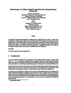
4 Experimental Results All quantizers were tested on an Intel Pentium-II 350 MHz PC with 256 MB RAM, using Visual C++ 6.0 Compiler on Windows 2000 Professional Version. The execution time and the quantization error were adopted as the factors for evaluating the performance of the color quantization algorithms. Table 1 showed the comparison of the uniform quantizer, five existing quantizers downloaded from the public domain and our quantizer with respects to the computational time and quality. The quantized images were shown on figure 4. Next experiments, we concentrated on the comparison between Wu’s quantizer, which outperforms the others, and our quantizer. Figure 2 and 3 showed the performance of both quantizers, based on PSNR and the execution time respectively on fifty test images. Table 2 presented the reduction of MSE after the number of representative colors was increased. In addition, Table 3 showed a breakdown of the computation times involved in four steps of Wu’s quantizer and our quantizer. Table 1. Execution time and Quantization Quality of different algorithms on a) “Mandrill” Image (512x512 pixels, 230,427 colors) and b) “Bird” Image (360x490 pixels, 126976 colors) . Execution time (sec)
MSE
Uniform
0.03
2056.01
18.59
Uniform
0.02
2014.35
19.86
Median-Cut
0.22
652.14
23.58
Median-Cut
0.18
425.32
26.61
Variance-Based
0.24
178.01
29.22
Variance-Based
0.19
132.07
31.69
0.13
83.18
33.70
177.63
30.40 33.44
Quantizers
Execution time (sec)
MSE PSNR (dB)
Quantizers
PSNR (dB)
Wu's Quantizer
0.19
118.63
30.98
Wu's Quantizer
Octree
6.84
196.40
28.79
Octree
4.43
NeuQuant (SF=1)
7.76
115.25
31.10
NeuQuant (SF=1)
4.74
88.18
NeuQuant (SF=30)
2.36
192.56
28.88
NeuQuant (SF=30)
1.24
166.96
30.67
Our Approach
0.10
150.58
29.94
Our Approach
0.07
128.21
31.82
(a)
(b)
782
Proc. VIIth Digital Image Computing: Techniques and Applications, Sun C., Talbot H., Ourselin S. and Adriaansen T. (Eds.), 10-12 Dec. 2003, Sydney
PSNR
50 40 30 20 10
0 Sample No.
Wu's Quantizer
Our Quantizer
Limit Quality
Lower Limit
Fig. 2. Comparison between Wu’s quantizer and our quantizer based on PSNR. Exe. time
0.45 0.4 0.35 0.3 0.25 0.2 0.15 0.1 0.05 0
Wu's Quantizer
Sample No.
Our Quantizer
Fig. 3. Comparison between Wu’s quantizer and our quantizer based on the execution time.
Table 2. MSE Reduction according to increasing the number of representative colors on a) “Mandrill” image and b) “Bird” image No. of Colors 2
4
8
16
32
64
128
256
MSE
PSNR (dB)
Wu's
Quantizer
5246.20
14.53
Our Approach
5292.53
14.49
Wu's
2655.40
17.48
Our Approach
2879.24
17.13
Wu's
1273.88
20.67
Our Approach
1367.80
20.37
Wu's
778.17
22.81
Our Approach
846.01
22.45
Wu's
468.33
25.02
Our Approach
546.47
24.35
Wu's
288.35
27.13
Our Approach
375.51
25.98
Wu's
186.54
29.02
Our Approach
226.07
28.18
Wu's
118.63
30.98
Our Approach
150.59
29.95
No. of Colors 2
4
8
16
32
64
128
256
(a)
MSE
PSNR (dB)
Wu's
Quantizer
3405.89
17.58
Our Approach
3619.19
17.32
Wu's
1788.39
20.38
Our Approach
2161.66
19.55
Wu's
1004.62
22.88
Our Approach
1108.60
22.45
Wu's
576.94
25.29
Our Approach
841.29
23.65
Wu's
346.28
27.51
Our Approach
453.94
26.33
Wu's
215.03
29.58
Our Approach
316.49
27.90
Wu's
131.80
31.70
Our Approach
207.36
29.73
Wu's
83.18
33.70
Our Approach
128.21
31.82
(b)
783
Proc. VIIth Digital Image Computing: Techniques and Applications, Sun C., Talbot H., Ourselin S. and Adriaansen T. (Eds.), 10-12 Dec. 2003, Sydney
Table 3. Comparison between Wu’s quantizer and our quantizer based on a breakdown of computation time algorithms on a) “Mandrill” Image and b) “Bird” Image. Quantizers
Wu's Quantizer
Our Quantizer
0.129
0.047
Histogram (sec)
Moment (sec)
0.020
0.011
Palette Design (sec)
0.022
0.020
Pixel Mapping (sec)
0.016
Total (sec)
0.187
Histogram (sec)
Quantizers
Wu's Quantizer
Our Quantizer
0.073
0.031
Moment (sec)
0.020
0.011
Palette Design (sec)
0.022
0.019
0.017
Pixel Mapping (sec)
0.011
0.011
0.095
Total (sec)
0.126
0.072
(a)
(a)
(b)
(b)
(c)
Fig. 4. “Mandrill” Image, “Bird” Image and “Flower” Image are quantized to 256 colors: a) Original, b) Wu’s quantizer and c) Our quantizer.
5 Conclusion and Future Works A new approach has been proposed because of the requirement of time reduction. Our experiments show that our quantizer reduces the execution time for color quantization
784
Proc. VIIth Digital Image Computing: Techniques and Applications, Sun C., Talbot H., Ourselin S. and Adriaansen T. (Eds.), 10-12 Dec. 2003, Sydney
process while the PSNR of 88% of one hundred test images is more than 30 dB, which is our limit quality. Our approach is suitable for the applications which required fast execution time and can display a full-color image using limited number of colors at a time such as a graphical signboard. However, a few test samples which are high quality photographic images with gradually shaded areas encountered a form of distortion of visible contouring in the specific area. This is the main point to be remedial in the future. We would like to thank NECTEC, Thailand for funding.
References 1. 2. 3. 4. 5. 6. 7. 8. 9.
10. 11. 12. 13. 14.
15. 16. 17.
P. Heckbert, Color image quantization for frame buffer displays, Computer Graphics, Vol. 16, No. 3, (1982) 297–307. S.J. Wan, P. Prusinkiewicz, and S.K.M. Wong, Variance-based color image quantization for frame buffer display, Color Research and Application, Vol. 15, No. 1, (1990) 52-58. J. H. Friedman, J. L. Bentley, and R.A. Finkel, An algorithm for finding best matches in logarithmic expected time, ACM Trans. Math. Software, Vol. 3, No. 3, (1977) 209-226. J. F. McGowan, John McGowan’s AVI Overview, http://www.jmcgowan.com/, (2000). M. Gervautz and W. Purgathofer, A simple method for color quantization: Octree quantization, Graphic Gems, Academic Press, New York (1990) 287–293. X. Wu, Color Quantization by Dynamic Programming and Principal Analysis, ACM Transactions on Graphics, Vol. 11, No. 4, (1992) 348-372. Y. Linde, A. Buzo, and R. Gray, An algorithm for vector quantizer design, IEEE Transactions on Communications, Vol. 28, No. 1, (1980) 84–95. S. Sangwine and R. Horne, The Colour Image Processing Handbook, Chapman & Hall, 1998. Y.W. Lim and S.U. Lee, On the color image segmentation algorithm based on the thresholding and the fuzzy c-means techniques, Pattern Recognition, Vol. 23, (1990) 935952. P. Scheunders, A comparison of clustering algorithms applied to color image quantization, Pattern Recognition Letters, Vol. 18, (1997) 1379-1384. P. Scheunders, A genetic C-means clustering algorithm applied to color image quantization, Pattern Recognition, Vol. 30, No. 6, (1997) 859-866. T. Kohonen, Self-Organization and Associative Memory, Springer-Verlag, Berlin, 1989. A. Dekker, Kohonen neural networks for optimal colour quantization, Network: Computation in Neural Systems, Vol. 5, (1994) 351–367. R. Balasubramanian, J.P. Allebach and C. Bouman, Sequential Scalar Quantization of Vectors: An Analysis, IEEE Transactions on Image Processing, Vol. 4, No. 9, (1995) 12821295. O. Verevka and J.W. Buchanan, Local k-means algorithm for color image quantization, Proceedings of Graphics Interface, (1995) 128-135. N. Papamakos, A. Atsalakis and C. Strouthopoulos, Adaptive Color Reduction, IEEE Systems Man and Cybermetic – Part B, Vol. 32, No. 1, (2002) 44-56. A. Schrader and F. Wittgruber, Fast Color Quantization of JPEG Images, Proceedings of the Second International Conference on Technical Informatics CONTI'96, Vol. 2, Timisoara, Romania, (1996) 109-116.
785