Moving-base 6-DOF Parallel Manipulator. António M. Lopes. Unidade de Integração de Sistemas e Processos Automatizados,. Faculdade de Engenharia ...
Fast Dynamic Model of a Moving-base 6-DOF Parallel Manipulator
361
18 x
Fast Dynamic Model of a Moving-base 6-DOF Parallel Manipulator António M. Lopes
Unidade de Integração de Sistemas e Processos Automatizados, Faculdade de Engenharia, Universidade do Porto Portugal 1. Introduction Dynamic models play an important role in parallel manipulators simulation and control. Mainly in the later case, the efficiency of the involved computations is of paramount importance, because manipulator real-time control is usually necessary (Zhao & Gao, 2009). The dynamic model of a parallel manipulator operating in free space can be represented in Cartesian coordinates by a system of nonlinear differential equations, which may be written in matrix form as I x x V x,x x G x f
(1)
Ix being the inertia matrix, V x,x the Coriolis and centripetal terms matrix, G x a vector of gravitational generalized forces, x the generalized position of the moving platform (or end-effector) and f the controlled generalized force applied on the end-effector. Thus, f J T x τ
(2)
where is the generalized force developed by the actuators and J(x) is the inverse kinematics jacobian matrix (Merlet, 2006). Dynamic modelling of parallel manipulators presents an inherent complexity, mainly due to system closed-loop structure and kinematic constraints. Several approaches have been applied to the dynamic analysis of parallel manipulators, the Newton-Euler and the Lagrange methods being the most popular ones (Do & Yang, 1988; Reboulet & Berthomieu, 1991; Ji, 1994; Dasgupta & Mruthyunjaya, 1998; Khalil & Ibrahim, 2007; Riebe & Ulbrich, 2003; Guo & Li, 2006; Nguyen & Pooran, 1989; Lebret et al., 1993; Di Gregório & ParentiCastelli, 2004; Caccavale et al., 2003; Dasgupta & Choudhury, 1999). These methods use classical mechanics principles, as is the case for all the approaches found in the literature, namely the ones based on the principle of virtual work (Staicu et al., 2007; Tsai, 2000; Wang & Gosselin, 1998), screw theory (Gallardo et al., 2003), recursive matrix method (Staicu & Zhang, 2008), Hamilton’s principle (Miller, 2004), and Kane’s equation (Liu et al., 2000).
362
Advances in Robot Manipulators
Thus, all approaches are equivalent, leading to equivalent dynamic equations. Nevertheless, these equations can present different levels of complexity and associated computational loads (Zhao & Gao, 2009). Minimizing the number of operations involved in the computation of the manipulator dynamic model has been the main goal of recent proposed techniques (Zhao & Gao, 2009; Staicu & Zhang, 2008; Abdellatif & Heimann, 2009; Wang et al., 2007; Sokolov & Xirouchakis, 2007; Bhattacharya et al., 1997; Carricato & Gosselin, 2009; Lopes, 2009). This book chapter presents the generalized momentum concept to model the dynamics of a Stewart platform manipulator having a non-stationary base platform. This is important, for example, in macro/micro robotic applications, where a small manipulator is attached in series to a big one. The later performs large amplitude movements, while the former is only responsible for the small motions. The book chapter is organized as follows. Section 2 presents a brief description of the parallel manipulator under study. In section 3 a complete dynamic model is developed. The generalized momentum approach is used and the motion of the manipulator base platform is considered. Conclusions are drawn in section 4.
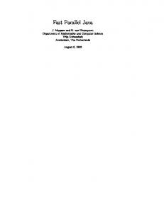
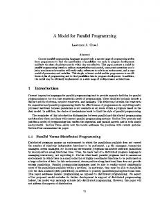
2. Manipulator Kinematic Structure A Stewart platform manipulator is being considered. It comprises a (usually) fixed platform (the base) and a moving platform (the payload platform), linked together by six independent, identical, open kinematic chains (Raghavan, 1993). In this book chapter a particular design will be considered as shown in Figure 1 (Fichter, 1986). In this case, each chain (leg) comprises a cylinder and a piston (or spindle) that are connected together by a prismatic joint, li. The upper end of each leg is connected to the moving platform by a spherical joint whereas the lower end is connected to the fixed base by a universal joint. Points Bi and Pi are the connecting points to the base and moving platforms, respectively (Figure 2). They are located at the vertices of two semi-regular hexagons inscribed in circumferences of radius rB and rP. The separation angles between points B1 and B6, B2 and B3, and B4 and B5 are denoted by 2B. In a similar way, the separation angles between points P1 and P2, P3 and P4, and P5 and P6 are denoted by 2P (Figure 2). zP
P3 xP
P4 Piston
l3
P2
P
P5
B4
l5
B3
P6
l2
l4 Cylinder
Moving platform P1
yP
l1 l6
zB
Base
xB B5
Fig. 1. Stewart platform kinematic structure
B
B2 B1
yB B6
Fast Dynamic Model of a Moving-base 6-DOF Parallel Manipulator
363
yB B2 B3
yP P2
B1
120º rB
B
xB
120º
B6
P
rP
P3
P1
60º
P P
xP
P
P4
60º
B4
P
P B5
P
P6
P5
Fig. 2. Position of the connecting points to the base and payload platforms For kinematic modelling purposes, two frames, {P} and {B}, are attached to the moving and base platforms, respectively. Its origins are the platforms centres of mass. The generalized position of frame {P} relative to frame {B} may be represented by the vector: B
where B x P pos and B x P o
E
B
xP
xP
P P
B| E
yP
[ xP
yP
z P P P P ]T [ B xTP pos
B B
xTP o ]T E
(3)
z P is the position of the origin of frame {P} relative to frame {B}, T
P defines an Euler angles system representing orientation of frame T
{P} relative to {B}. The used Euler angles system corresponds to the basic rotations (Vukobratovic & Kircanski, 1986): P about zP; P about the rotated axis yP’; and P about the rotated axis xP’’. The rotation matrix is given by:
B
C P C P R P S P C P S P
C P S P S P S P C P S P S P S P C P C P C P S P
C P S P C P S P S P S P S P C P C P S P C P C P
(4)
S() and C() correspond to the sine and cosine functions, respectively. The manipulator position and velocity kinematic models are well known, being obtainable from the geometrical analysis of the kinematics chains. The velocity kinematics is represented by the Euler angles jacobian matrix, JE, or the kinematic jacobian, JC (Merlet, 2006). These jacobians relate the velocities of the active joints (the actuators) to the generalized velocity of the moving platform:
364
Advances in Robot Manipulators
l J B x E P
(5)
B x P pos B JC B ωP B
(6)
B| E
l J B x C P
with
B x P pos B JE B x P ( o ) E
B
l l l l 1 2 6 B
ωP
B
J A B x P o
T
E
(7) (8)
and (Vukobratovic & Kircanski, 1986)
0 S P J A 0 C P 1 0 Vectors
B
x P pos B v P B
B
and
B
C P C P C P S P S P
(9)
ω P represent the linear and angular velocity of the moving B
platform relative to {B}, and B x P o represents the Euler angles time derivative. E
3. Complete Dynamic Modelling Using the Generalized Momentum Approach It is well known the generalized momentum of a rigid body, qc, may be computed from the following general expression: (10)
q c I c u c
Vector uc represents the generalized velocity (linear and angular) of the body and Ic is its inertia matrix. Vectors qc and uc and inertia matrix Ic must be expressed in the same frame of reference. Equation
(10) may also be written as
Q I c ( tra ) q c c H c 0
0 vc I c ( rot ) ω c
(11)
where Qc is the linear momentum vector due to rigid body translation and Hc is the angular momentum vector due to body rotation. Ic(tra) is the translational inertia matrix and Ic(rot) is the rotational inertia matrix. vc and ωc are the body linear and angular velocities. The inertial component of the generalized force (force and moment) acting on the body can be obtained from the time derivative of equation
(10):
Fast Dynamic Model of a Moving-base 6-DOF Parallel Manipulator
365
f c ine q c I c u c I c u c
(12)
with force and moment expressed in the same frame and f c ine FcT( ine )
M Tc ( ine ) . T
Equivalently, force and moment vectors are: I v I v Fc ( ine ) Q c c ( tra ) c c ( tra ) c
(13)
I c I c ( rot ) ω c M c ( ine ) H ω c c ( rot )
(14)
3.1 Payload Platform Modelling Considering the Stewart platform manipulator base motion, i.e., the motion of frame {B} relative to a fixed world frame {W}{xW, yW, zW}, the position of the payload platform, {P}, relative to {W} and expressed in {W}, may be given by W
p P W p B B p P W
where
W
pB
W
W
is the position of frame {B}, and
B
pP
(15)
W
represents the position of frame {P}
W
relative to {B} and expressed in {W}. The linear velocity of the payload platform, {P}, relative to {W} and expressed in {W}, may be obtained taking the time derivative of the previous equation, that is, W
v P W v B B v P W ω B W
where
W
vB
W
W
W
is the linear velocity of frame {B},
seen by an observer fixed in {B}, to {W}, and p P x P pos B
B
W
W
W
ωB
W
B
vP
W
W
BpP
(16)
W
is the linear velocity of frame {P} as
represents the angular velocity of frame {B} relative
represents the position of {P} relative to {B} and expressed in {W}.
In the following analysis, knowledge of the generalized position of frame {B} relative to {W}, W W xB [ xB yB z B B B B ]T [W xTB pos xTB o ]T , shall be assumed: W |E
W
x B pos
W
W
E
represents the position vector expressed in frame {W}, and
W
x B o represents the E
orientation expressed in an Euler angles system. Knowledge of its first and second time derivatives shall also be supposed i.e., W x B and W x B , respectively. Therefore, the W |E
orientation matrix,
W
W |E
R B , of frame {B} relative to {W} can be easily computed, and the
jacobian, JG, relating the angular velocity of the base frame relative to {W}, W ω B time derivative of the Euler angles,
W
W
, to the first
x B o , is given by E
W
ωB
W
J G W x B o
E
(17)
366
Advances in Robot Manipulators
Considering equation (16), in frame {B}, the following equation can be written: v P W v B B v P W ω B B p P
W
B
B
B
B
(18)
B
Therefore, the total linear momentum of {P} expressed in frame {B} will be Q P tot
B
mP W v P
(19)
B
mP being the payload platform mass. Taking the time derivative of the previous equation results in Q P tot
B
mP W v P
(20)
B
Knowing that, W
ω P B ω P W ω B B
W
B
(21)
B
P B ω P W ω B B ω P W ω B ω B
B
B
B
(22)
B
results in W
v P W v B B v P B
B
B
B B p P W ω B 2 W ω B B v P W ω B
B
B
B
B
W ωB BpP B
B
(23)
The inertial part of the total force applied in {P}, due to the payload platform translation, expressed in frame {B} will be P
FP ine tot
B
Q P tot
(24)
B
That is, P
FP ine tot P FP ine fix P FP ine man B
P
P
FP ine man
where P FP ine fix
B
B
mP
W
B
B
mP B v P
B
(25)
B
(26)
B
B B p P W ω B W ω B B p P 2 W ω B B v P W ω B
B
B
B
B
B
B
(27)
represents the inertial part of the force, considering the base platform is not
moving, and FP ine man P
motion.
v
FP ine fix
B
B
represents the inertial part of the force which results from the base
Fast Dynamic Model of a Moving-base 6-DOF Parallel Manipulator
367
On the other hand, the angular momentum of the moving platform, about its centre of mass and expressed in frame {B} will be H P tot
I P ( rot )
B
B
I P rot W ω P B
(28)
B
represents the rotational inertia matrix of the moving platform, expressed in the base
frame, {B}. This inertia matrix is given by: (29)
I P ( rot ) B R P I P ( rot ) B R TP B
where I P ( rot )
P
P
is a constant matrix representing the rotational inertia matrix of the moving
platform, expressed in frame {P}. Considering that I Pxx , I Pyy and I Pzz are the moments of inertia of the moving platform expressed in its own frame, this matrix may be written as:
I P ( rot )
P
diag([I Pxx
I Pyy
(30)
I Pzz ])
Taking the time derivative of equation (28) results in H P tot
B
I P rot W ω P B
B
P I P rot W ω B
(31)
B
The inertial part of the total moment applied in {P}, due to the payload platform rotation, expressed in frame {B} will be P
M P ine tot
B
H P tot
(32)
B
that is, P
M P ine tot P M P ine fix P M P ine man B
B
(33)
B
where, P
P
P
M P ine fix
B
M P ine man
M P ine fix B
B
P I P rot B ω
I P rot W ω B B
B
B
B
I P rot B ω P
B
(34)
B
B W ω B B ω P I P rot W ω B
B
B
B
(35)
represents the inertial part of the moment, considering the base platform is not
moving, and P M P ine man
B
represents the inertial part of the moment which results from the
base motion. The total inertial component of the generalized force applied to {P} and expressed in {B} will be
368
Advances in Robot Manipulators P
f P ine tot
B
[ P FPTine tot
P B
M TP ine tot ]T B
(36)
The inertial components of the forces in the manipulator actuators (actuating forces) will be τ P ine fix J CT P f P ine fix
B
τ P ine man J CT P f P ine man
B
(37) (38)
On the other hand, regarding the gravitational part of the generalized force, if the base platform orientation changes, then the force applied to {P} and expressed in {B} results in P
f P gra W TB P f P gra B
W
(39)
where, W
and P f P gra
W
W R B B 0
W
0 RB
(40)
is the gravitational generalized force applied to {P} and expressed in {W}. This
force can be computed using a simplified model that considers both a non-moving base platform, frame {B} parallel to {W}, and z B gˆ , i.e.,
P
f P gra
W
PP B x P xP
B| E
B
(41)
B| E
PP mP g z P representing the mobile platform potential energy.
The gravitational component of the actuating forces due to the moving platform, τ P gra , is given by equation (42), which can be added to equations (37) and (38). τ P gra J C T P f P gra
(42)
B
3.2 Cylinder Modelling Position of the cylinder i, relative to {W} and expressed in {W}, may be computed using the following equation: W
p Ci
W
W p B B p Ci W
W
(43)
The linear velocity of the cylinder, relative to {W} and expressed in {W}, may be obtained taking the time derivative of the previous equation, that is,
Fast Dynamic Model of a Moving-base 6-DOF Parallel Manipulator W
v Ci
W
W v B B v Ci W
W
W ω B
369
B p Ci
W
(44)
W
Considering that frame {Ci} is attached to the cylinder i and positioned at its centre of mass, then B v Ci is the linear velocity of frame {Ci} as seen by an observer fixed in {B}, and B p Ci W
W
represents the position of {Ci} relative to {B} and expressed in {W}. In frame {B} the following equation can be written: W
v Ci W v B B v Ci W ω B B
B
B
B
B p Ci
(45)
B
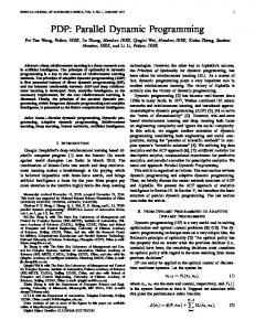
Considering the centre of mass of each cylinder is located at a constant distance, bC, from the cylinder to base platform connecting point, Bi, (Figure 3), then its position relative to frame {B} is B
p Ci
B
bC ˆl i b i
(46)
where,
ˆl l i l i i li li l i B x P pos P p i B
Pi
P
(47)
B
(48)
bi
pi
P B
li B
pCi
bC
Bi
xP pos
B
zB
B
bi
xB
Fig. 3. Position of the centre of mass of the cylinder i The linear velocity of the cylinder centre of mass, B p Ci
B
B
yB
, relative to {B} and expressed in the
same frame, may be computed as: B
p Ci B ω li B
where B ω li
B
B
bC ˆl i
represents the leg angular velocity, which can be found from:
(49)
370
Advances in Robot Manipulators B
ω li
l i B v P B ω P P p i B
B
B
(50)
B
As the leg (both the cylinder and piston) cannot rotate along its own axis, the angular velocity along ˆl i is always zero, and vectors li and B ω li are always perpendicular. This B
enables equation (50) to be rewritten as: B
ω li
B
1 l i B v P B ω P P p i B B l Ti l i
B
(51)
or, ω li
B
B
B vP B J Di B ω P B
(52)
where jacobian J Di is given by:
~ ~ ~T J Di li li P p i B li
and, for a given vector a a x
ay
li li li
(53) (54)
T
az , T
0 ~ a az a y
az 0 ax
ay ax 0
(55)
On the other hand, equation (49) can be rewritten as:
B
p Ci
B
B vP J Bi B ω P
B
B
(56)
where the jacobian J Bi is given by: ~ ~ ~ ~ ~T J Bi bC ˆli T li bC ˆli T li P p i B
The total linear momentum of the cylinder i, expressed in frame {B} will be
(57)
Fast Dynamic Model of a Moving-base 6-DOF Parallel Manipulator
Q Ci tot
mC W v Ci
B
371
(58)
B
mC being the cylinder mass. Taking the time derivative of the previous equation results in
Q Ci tot
mC W v Ci
B
(59)
B
where, W
v Ci W v B B v Ci B
B
B
B B p C W ω B W ω B B p C 2 W ω B B v Ci W ω i i B
B
B
B
B
B
B
(60)
The inertial part of the total force applied in {Ci}, due to the cylinder translation, expressed in frame {B} will be Ci
FCi ine tot
B
Q Ci tot
(61)
B
That is, Ci
FCi ine tot Ci FCi ine fix Ci FCi ine man B
B
Ci
Ci
where
Ci
FCi ine man
FCi ine fix
B
not moving, and
B
FC i ine fix
mC
v
B
W
B
B
mC B v C
i
B
mC J Bi B x P
B
(62)
B
mC J Bi B x P
(63)
B
B B p C W ω B W ω B B p C 2 W ω B B v Ci W ω i i B
B
B
B
B
B
B
(64)
represents the inertial part of the force, considering the base platform is Ci
FCi ine man
B
represents the inertial part of the force which results from the
base motion. When equation (61) is pre-multiplied by J TBi , the inertial component of the generalized force applied to {P}, due to each cylinder translation is obtained in frame {B}: P
f Ci ine tot tra
B
J TBi Ci FCi ine tot
B
(65)
The inertial components of the actuating forces will be τ Ci ine fix tra J C T P f Ci ine fix tra τ Ci ine man tra J C T P f Ci ine man tra
B
B
(66) (67)
On the other hand, the total angular momentum of the cylinder about its centre of mass and expressed in frame {B} will be:
372
Advances in Robot Manipulators
H Ci tot
B
I Ci rot W ω Ci
(68)
B
B
Taking the time derivative of the previous equation results in
H Ci tot
B
I Ci rot W ω Ci
B
B
C I Ci rot W ω i B
B
(69)
where, W
ω Ci B ω Ci W ω B B
B
W
C B ω C W ω B B ω C W ω B ω i i i
Ci
B
B
B
B
Considering that I Ci rot
(70)
B
B
(71)
is the inertia constant matrix of the rotating cylinder i, expressed in
the frame fixed to the cylinder itself, {Ci}{ x Ci ,y Ci ,z Ci }, then (72)
I Ci rot B R Ci I Ci rot B R TCi Ci
B
where B R Ci is the orientation matrix of each cylinder frame, {Ci}, relative to the base frame, {B}. Cylinder frames were chosen in the following way: axis x Ci coincides with the leg axis and points towards Pi; axis y Ci is perpendicular to x Ci and always parallel to the base plane, this condition being possible given the existence of a universal joint at point Bi, that negates any rotation along its own axis; axis z Ci completes the referential following the right hand rule, and its projection along axis zB is always positive. Thus, matrix B R Ci becomes: B
R C i x Ci
y Ci
z Ci
(73)
where
x Ci ˆl i liy y Ci 2 lix liy2
(74) 0
lix lix2 liy2
T
(75) (76)
z Ci x Ci y Ci So, the inertia matrices of the cylinders can be written as: I Ci rot
Ci
diag([ I C xx
I C yy
I C zz ])
where I Cxx , I C yy and I Czz are the cylinder moments of inertia expressed in its own frame.
(77)
Fast Dynamic Model of a Moving-base 6-DOF Parallel Manipulator
373
The inertial part of the total moment applied in {Ci}, due to the cylinder rotation, expressed in frame {B} will be
M Ci ine tot
Ci
B
H Ci tot
(78)
B
that is, Ci
M Ci ine tot Ci M Ci ine fix Ci M Ci ine man B
B
(79)
B
where, Ci
Ci
Ci
M Ci ine fix
B
M Ci ine fix
M Ci ine man
B
B
d I J Di B x P dt Ci rot B
I Ci rot W ω B B
B
I Ci rot J Di B x P
B
B
B W ω B B ω C I Ci rot W ω i B
B
B
(80)
B
B
(81)
represents the inertial part of the moment, considering the base platform is not
moving, and
Ci
M Ci ine man
B
represents the inertial part of the moment which results from the
base motion. When equation (78) is pre-multiplied by J TDi , the inertial component of the generalized force applied to {P}, due to each cylinder rotation is obtained in frame {B}: P
fCi ine tot rot
B
J TDi Ci M Ci ine tot
B
(82)
The inertial components of the actuating forces will be τ Ci ine fix rot J C T P fCi ine fix rot τ Ci ine man rot J C T P fCi ine man rot
B
B
(83) (84)
Now, with reference to the gravitational part of the generalized force, if the base platform orientation changes, then the force applied in {P} and expressed in {B} results in P
fCi gra W TB P fCi gra B
where P fCi gra
W
(85)
W
is the gravitational generalized force applied in {P} and expressed in {W}.
This force can be computed using the model that considers both a non-moving base platform, frame {B} parallel to {W}, and z B gˆ , i.e.,
P
f Ci gra
W
PCi B x P xP
B| E
B
B| E
(86)
374
Advances in Robot Manipulators
PCi being the cylinder potential energy. Using equation (46) it can be computed by: PCi mC g
bC z P P pi li
Bz
(87)
The gravitational component of the actuating forces due to each cylinder, τ Ci gra , is τ Ci gra J C T P f Ci gra
(88)
B
3.3. Piston Modelling Position of the piston i, relative to {W} and expressed in {W}, may be computed using the following equation: W
p Si
W
W p B
W
B p Si
(89)
W
The linear velocity of the piston, relative to {W} and expressed in {W}, may be obtained taking the time derivative of the previous equation, that is, W
v Si
W v B
W
W
B v Si
W
W ω B
W
B p Si
W
(90)
Considering that frame {Si} is attached to the piston i and positioned at its centre of mass, then B v Si is the linear velocity of frame {Si} as seen by an observer fixed in {B}, and B p Si W
W
represents the position of {Si} relative to {B} and expressed in {W}. In frame {B} the following equation can be written: W
v S i W v B B v S i W ω B B p S i B
B
B
B
B
(91)
If the centre of mass of each piston is located at a constant distance, bS, from the piston to moving platform connecting point, Pi, (Figure 4), then its position relative to frame {B} is: B
p Si
B
bS ˆl i B p i B x P pos B
The linear velocity of the piston centre of mass, B p Si same frame, may be computed as: B
p Si
B
l i B ω li
B
B
B
(92)
, relative to {B} and expressed in the
bS ˆl i
(93)
Fast Dynamic Model of a Moving-base 6-DOF Parallel Manipulator
B
p Si
375
B vP B J Gi B ω P B
B
(94)
where the jacobian J Gi is given by:
~ ~ ~ ~ ~T J Gi I bS ˆli T li I bS ˆli T li P p i B Pi
P
bS
li
pi
(95)
P B
xP pos
B
B
pSi
B
Bi
zB
bi
xB
Fig. 4. Position of the centre of mass of the piston i
yB
B
The total linear momentum of the piston i, expressed in frame {B} will be Q Si tot
mS W v Si
B
(96)
B
mS being the piston mass. Taking the time derivative of the previous equation results in
Q S i tot
mS W v Si
B
(97)
B
where, W
v Si W v B B v Si B
B
B
B B p S W ω B W ω B B p S 2 W ω B B v Si W ω i i B
B
B
B
B
B
B
(98)
The inertial part of the total force applied in {Si}, due to the piston translation, expressed in frame {B} will be Si
FSi ine tot
B
Q S i tot
(99)
B
That is, Si
FSi ine tot Si FSi ine fix Si FSi ine man B
B
B
(100)
376
Advances in Robot Manipulators
Si
Si
where
Si
FSi ine man
FSi ine fix
B
not moving, and
B
FS i ine fix
mS
v
B
W
B
B
mS B v S
i
mS J Gi B x P
B
B
mS J Gi B x P
(101)
B
B B p S W ω B W ω B B p S 2 W ω B B v Si W ω i i B
B
B
B
B
B
B
(102)
represents the inertial part of the force, considering the base platform is Si
FSi ine man
B
represents the inertial part of the force which results from the
base motion. When equation (99) is pre-multiplied by J TGi , the inertial component of the generalized force applied to {P}, due to each piston translation is obtained in frame {B}: P
f Si ine tot tra
B
J TGi Si FSi ine tot
(103)
B
The inertial components of the actuating forces will be τ Si ine fix tra J C T P f Si ine fix tra τ Si ine man tra J C T P f Si ine man tra
(104)
B
(105)
B
On the other hand, the total angular momentum of the piston about its centre of mass, expressed in frame {B}, will be: H Si tot
B
I Si rot W ω Si B
(106)
B
Taking the time derivative of the previous equation results in
H Si tot
B
I Si rot W ω Si B
B
S I Si rot W ω i B
B
(107)
where, W
ω Si B ω Si W ω B B
W
Si
B
B
(108)
B
S B ω S W ω B B ω S W ω B ω i i i B
Considering that I Si rot
B
B
B
(109)
is the inertia constant matrix of the rotating piston i, expressed in
the frame fixed to the piston itself, {Si}, then
I Si rot B R Si I Si rot B R TSi B
where
B
Si
(110)
R Si is the orientation matrix of each piston frame, {Si}, relative to the base frame, {B}.
Fast Dynamic Model of a Moving-base 6-DOF Parallel Manipulator
377
As the relative motion between cylinder and piston is a pure translation, {Si} can be chosen parallel to {Ci}. Therefore, B R Si = B R Ci . So, the inertia matrices of the pistons can be written as: I Si rot
Si
diag([ I S xx
I S yy
(111)
I S zz ])
where I S xx , I S yy and I S zz are the piston moments of inertia expressed in its own frame. The inertial part of the total moment applied in {Si}, due to the piston rotation, expressed in frame {B} will be Si
M Si ine tot
B
H S i tot
(112)
B
that is, Si
M Si ine tot Si M Si ine fix Si M Si ine man B
B
(113)
B
where, Si
Si
Si
M Si ine fix
B
M Si ine fix
M Si ine man
B
B
d I J Di B x P dt Si rot B
I Si rot W ω B B
B
B
I Si rot J Di B x P B
B W ω B B ω S I Si rot W ω i B
B
(114)
B
B
B
(115)
represents the inertial part of the moment, considering the base platform is not
moving, and
Si
M Si ine man
B
represents the inertial part of the moment which results from the
base motion. When equation (112) is pre-multiplied by J TDi , the inertial component of the generalized force applied to {P}, due to each piston rotation is obtained in frame {B}: P
f Si ine tot rot
B
J TDi Si M Si ine tot
B
(116)
The inertial components of the actuating forces will be τ Si ine fix rot J C T P f Si ine fix rot τ Si ine man rot J C T P f Si ine man rot
B
B
(117) (118)
Now, with reference to the gravitational part of the generalized force, if the base platform orientation changes, then the force applied in {P} and expressed in {B} results in P
f Si gra W TB P f Si gra B
W
(119)
378
where P f Si gra
Advances in Robot Manipulators
W
is the gravitational generalized force applied in {P} and expressed in {W}.
This force can be computed using the model that considers both a non-moving base platform, frame {B} parallel to {W}, and z B gˆ , i.e.,
P
f Si gra
W
PSi B x P xP
B| E
(120)
B
B| E
PS i being the piston potential energy. Using equation (92) it can be computed by: b PSi mS g 1 S li
z P P pi
Bz
(121)
The gravitational component of the actuating forces due to each piston, τ Si gra , is τ Si gra J C T P f Si gra
B
(122)
It should be noted that the base platform motion originates new inertial contributions to the parallel manipulator dynamic model, expressed by equations (38), (67), (84), (105) and (118). These contributions should the added to the corresponding ones resulting from the model that considers a fixed-base: equations (37), (66), (83), (104) and (117). Regarding the gravitational part of the dynamic model, the base platform motion modifies the gravitational force components, resulting in the equations (42), (88) and (122), which can also be added to the previous ones. Computational efficiency of the proposed model has been evaluated by counting the number of scalar operations needed in the calculations (sums, multiplications and divisions). For this purpose, the Maple® software package was used. The results were then compared with the ones obtained by using the Lagrange formulation. The generalized momentum approach resulted in a much more efficient dynamic model. Regarding the total number of sums and multiplications involved in the two models, the ratio is five, approximately. This might be a great advantage if real-time simulation and control is needed.
4. Conclusion A parallel manipulator is a complex multi-body dynamic system having several closed loops. Typically, it is composed of a (usually) fixed base platform and a moving payload platform, connected by at least two independent open kinematic chains. Dynamic modelling of parallel manipulators presents an inherent difficulty. Despite the intensive study in this topic of robotics, mostly conducted in the last two decades, additional research still has to be done in this area.
Fast Dynamic Model of a Moving-base 6-DOF Parallel Manipulator
379
In this book chapter an approach based on the manipulator generalized momentum was explored and applied to the dynamic modelling of a Stewart platform manipulator. The system dynamic equations were obtained for the general case of a non-fixed base platform. It was shown the base platform motion originates new inertial force contributions to the parallel manipulator dynamic model. Compact analytical expressions for these contributions were presented and it was shown they can be easily added to the corresponding ones resulting from the model that considers a fixed base. On the other hand, regarding the gravitational part of the dynamic model, the base platform motion modifies the gravitational force components derived when considering a fixed base platform. Analytical expressions for these components were also presented. Computational efficiency of the dynamic model was evaluated by counting the number of scalar operations that are needed. The results were then compared with the ones obtained by using the Lagrange formulation. The generalized momentum approach results in a much more efficient dynamic model.
5. References Abdellatif, H. & Heimann, B. (2009). Computational efficient inverse dynamics of 6-DOF fully parallel manipulators by using the Lagrangian formalism. Mechanism and Machine Theory, Vol. 44, 192-207 Bhattacharya, S., Hatwal, H. & Ghosh, A. (1997). An on-line estimation scheme for generalized Stewart platform type parallel manipulators. Mech. Mach. Theory, Vol. 32, 79-89 Caccavale, F., Siciliano, B. & Villani, L. (2003). The tricept robot: Dynamics and impedance control. IEEE/ASME Transactions on Mechatronics, Vol. 8, 263-268 Carricato, M. & Gosselin, C. (2009). On the Modeling of Leg Constraints in the Dynamic Analysis of Gough/Stewart-Type Platforms. J. Comput. Nonlinear Dynamics, Vol. 4, DOI:10.1115/1.3007974 Dasgupta, B. & Choudhury, P. (1999). A general strategy based on the Newton-Euler approach for the dynamic formulation of parallel manipulators. Mech. Mach. Theory, Vol. 34, 801-824 Dasgupta, B. & Mruthyunjaya, T. (1998). A Newton–Euler formulation for the inverse dynamics of the Stewart platform manipulator. Mechanism and Machine Theory, Vol. 34, 711-725 Di Gregório, R. & Parenti-Castelli, V. (2004). Dynamics of a class of parallel wrists. Journal of Mechanical Design, Vol. 126, 436-441 Do, W. & Yang, D. (1988). Inverse dynamic analysis and simulation of a platform type of robot. Journal of Robotic Systems, Vol. 5, 209-227 Fichter, E. (1986). A Stewart Platform-Based Manipulator: General Theory and Practical Construction. The Int. Journal of Robotics Research, Vol. 5, 157-182 Gallardo, J., Rico, J., Frisoli, A., Checcacci, D. & Bergamasco, M. (2003). Dynamics of parallel manipulators by means of screw theory. Mechanism and Machine Theory, Vol. 38, 1113-1131 Guo, H. & Li, H. (2006). Dynamic analysis and simulation of a six degree of freedom Stewart platform manipulator. Proceedings of the Institution of Mechanical Engineers, Part C: Journal of Mechanical Engineering Science, Vol. 220, 61-72
380
Advances in Robot Manipulators
Ji, Z. (1994). Dynamics decomposition for Stewart platforms. ASME Journal of Mechanical Design, Vol. 116, 67-69 Khalil, W. & Ibrahim, O. (2007). General solution for the dynamic modelling of parallel robots. Journal of Intelligent and Robot Systems, Vol. 49, 19-37 Lebret, G., Liu, K. & Lewis, F. (1993). Dynamic analysis and control of a Stewart platform manipulator. Journal of Robotic Systems, Vol. 10, 629-655 Liu, M-J., Li, C-X. & Li, C-N. (2000). Dynamics analysis of the Gough-Stewart platform manipulator. IEEE Trans. Robotics and Automation, Vol. 16, 94-98 Lopes, A. M. (2009). Dynamic modeling of a Stewart platform using the generalized momentum approach. Communications in Nonlinear Science and Numerical Simulation, Vol. 14, 3389–3401 Merlet, J-P. (2006). Parallel Robots, Springer, Dordrecht, Netherlands Miller, K. (2004). Optimal design and modeling of spatial parallel manipulators. Int. J. Robotics Research, Vol. 23, 127-140 Nguyen, C. & Pooran, F. (1989). Dynamic analysis of a 6 DOF CKCM robot end-effector for dual-arm telerobot systems. Robotics and Autonomous Systems, Vol. 5, 377-394 Raghavan, M. (1993). The Stewart Platform of General Geometry has 40 Configurations. ASME Journal of Mechanical Design, Vol. 115, 277-282 Reboulet, C. & Berthomieu, T. (1991). Dynamic Models of a Six Degree of Freedom Parallel Manipulators, Proceedings of the IEEE Int. Conf. on Robotics and Automation, pp. 11531157 Riebe, S. & Ulbrich, H. (2003). Modelling and online computation of the dynamics of a parallel kinematic with six degrees-of-freedom. Archive of Applied Mechanics, Vol. 72, 817-829 Sokolov, A. & Xirouchakis, P. (2007). Dynamics analysis of a 3-DOF parallel manipulator with R-P-S joint structure. Mechanism and Machine Theory, Vol. 42, 541-557 Staicu, S. & Zhang, D. (2008). A novel dynamic modelling approach for parallel mechanisms analysis. Robotics and Computer-Integrated Manufacturing, Vol. 24, 167-172 Staicu, S., Liu, X.-J. & Wang, J. (2007). Inverse dynamics of the HALF parallel manipulator with revolute actuators. Nonlinear Dynamics, Vol. 50, 1-12 Tsai, L.-W. (2000). Solving the inverse dynamics of Stewart-Gough manipulator by the principle of virtual work. Journal of Mechanical Design, Vol. 122, 3-9 Vukobratovic, M. & Kircanski, M. (1986). Kinematics and Trajectory Synthesis of Manipulation Robots, Springer-Verlag, Berlin Wang, J. & Gosselin, C. (1998). A new approach for the dynamic analysis of parallel manipulators. Multibody System Dynamics, Vol. 2, 317-334 Wang, J., Wu, J., Wang, L. & Li, T. (2007). Simplified strategy of the dynamic model of a 6UPS parallel kinematic machine for real-time control. Mechanism and Machine Theory, Vol. 42, 1119-1140 Zhao, Y. & Gao, F. (2009). Inverse dynamics of the 6-dof out-parallel manipulator by means of the principle of virtual work. Robotica, Vol. 27, 259–268