Fast neural network for synthesis and implementation of orthogonal wavelet transform Jan Stolarek1 and Mykhaylo Yatsymirskyy1 Institute of Computer Science, Technical University of Lodz, ul. Wolczanska 215, 93-005 Lodz, Poland,
[email protected],
[email protected] Summary. This paper presents lattice structure and orthogonal lattice structure for synthesis of a wavelet transform. Lattice structure is based on parametrized 2 × 2 operations. Adjustment of parameter values leads to synthesis of a new wavelet transform. Fast neural network with topology based on lattice structure is applied to determine values of the parameters. Factorization–based reduction in number of arithmetic operations is demonstrated. Key words: signal processing, wavelet transform, neural networks
1 Introduction During the last two decades, wavelet transform became an important tool in the area of compression, analysis and processing of signals. The most popular are the Daubechies wavelets [1] that are well suited for analysis of many natural signals and offer a straightforward interpretation of the result. Many other kinds of wavelets have been designed, each with its unique characteristics. However, there is no single wavelet perfectly suitable for every task. It is very important, that chosen wavelet family closely corresponds to characteristics of analysed signal. Therefore it is important to develop a method to adaptively synthesize a wavelet most suitable for particular task. Some attempts in that field have already been made. In [10] parametrization of wavelet transform was proposed. This allows adjusting wavelet’s properties by optimization of parameters. In [4] and [9] lattice structure for designing two–channel perfect reconstruction filters was presented. This approach was based on representing a filter bank in a form of parametrized lattice structure. Parameters were then optimized using well–known numerical methods (e.g. quasi–Newton method) and the resulting values, together with the lattice structure, defined the filter.
2
Jan Stolarek and Mykhaylo Yatsymirskyy
This paper presents method for synthesis of a wavelet transform, based on generalized lattice structure [11]. Fast Neural Network is used to determine optimal values of parameters.
2 Lattice structure Let us consider two–point base operation · k k ¸ d d12 Dk = 11 , dk21 dk22
(1)
where k stands for the index of operation. Let us assume that Dk is invertible, i.e. condition dk11 dk22 − dk21 dk12 6= 0 holds true. Hence there exists inverse transformation Dk−1 such that Dk Dk−1 = I, where I is the identity matrix. a)
b)
x0 (n)
D1
x1 (n) x2 (n)
D1
D3
D1 D2
x5 (n) x6 (n)
t2 D3
D2
x3 (n) x4 (n)
t1 D2
D2
x7 (n)
y1 (n)
y2 (n)
y2 (n)
y4 (n) y5 (n)
D3
t1
y0 (n)
y1 (n)
y3 (n) D3
D1
y0 (n)
t2
y4 (n)
D2−1
y7 (n)
y7 (n)
x4 (n) x5 (n)
D1−1 D2−1
D3−1
x2 (n) x3 (n)
D1−1
D3−1
x0 (n) x1 (n)
D1−1
D3−1
y5 (n) y6 (n)
D1−1
D2−1
y3 (n)
y6 (n)
c)
t1 D3−1
t2 D2−1
x6 (n) x7 (n)
t2 t1
d) a1 a2
Dk
b1 =
a1 dk11
b2 =
a1 dk21
+
a2 dk12
b1
+
a2 dk22
b2
Dk−1
a1 a2
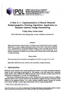
Fig. 1. The lattice structure for K = 6, N = 8 : a) forward, b) inverse. Base operations: c) forward, d) inverse
We introduce forward lattice structure that is composed of K/2 stages, each containing Dk operations repeated N/2 times, where K and N are the lengths of the filter’s impulse response and of the processed signal respectively (see Figure 1a). In the first stage the pairs of x2i and x2i+1 samples are assigned to the inputs of each Dk operation, i = 0, 1, . . . , N/2 − 1. Base operations in successive stages are shifted down by one position and the lower
Fast neural network for synthesis and implementation of orthogonal...
3
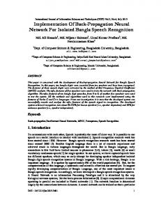
input of the last base operation in the current stage is connected to the upper output of the first base operation in the preceding stage. In other words we perform the cyclic N –element shift of the mentioned outputs to the left (upward). The outputs of the last stage are the outputs yi of the whole structure, where i = 0, 1, . . . , N − 1. The inverse lattice structure emerges as the reversed forward structure, where base Dk operations are substituted by inverse operations Dk−1 and the cyclic shift is performed in the opposite direction. Figure 1b shows inverse structure for the structure presented in Figure 1a. The cyclic left (Figure 1a) and right (Figure 1b) shift operations are represented by t1 and t2 symbols. In structures presented on Figure 1a and 1b all Dk operations within one stage are identical. However it is possible, that Dk operations within single stage are different. This allows for more precise adjustment of filter’s properties. Let us now estimate the number of arithmetic operations in the proposed structures. In a general case in order to execute K/2 stages while operating on N samples of a signal it is required to perform the number of (N/2)(K/2) base operations Dk , where each operation requires two additions and four multiplications. Hence the forward and the inverse structures require α(K, N ) additions and µ(K, N ) multiplications separately where α(K, N ) = KN/2 and µ(K, N ) = KN . In other words for one pair of the processed elements each structure requires K additions and 2K multiplications. In order to achieve reduction in the number of arithmetic operations it is required to consider the particular base operations. This will be presented in the next section of this paper. The main advantage of the proposed lattice structure is the ease of its realization in the pipelined scheme. In a general case the pipeline scheme contains K/2 blocks of base operations and K/2 − 1 blocks z −1 with delays by one element, see Figure 2. y2i
x2i D1 x2i+1
D2 z −1
DK
D3 z −1
z −1
2
y2i+1
Fig. 2. The pipeline scheme for K/2–stage lattice structure
In the scheme in Figure 2 there is no cyclic shift which must be performed within the hardware or software implementation, e.g. by cyclic repetition of the first samples of input signal. The proposed pipeline scheme is simpler than the well-known lifting one. Firstly it reduces the number of required two-point base operations, e.g. by one for K = 4 and K = 6. Moreover, it utilizes the base operations of one type and all delays are placed outside base operations. In the lifting structure delays and z 1 shifts are enclosed within base operations.
4
Jan Stolarek and Mykhaylo Yatsymirskyy
3 Orthogonal lattice structure Let us assume that Dk transformation is orthogonal, which implies that condition dk11 dk21 + dk12 dk22 = 0 holds true. We will consider two cases of such transformations : •
symmetric, when Sk = Sk−1 Sk =
•
Sk−1
·
p q = k k qk −pk
¸ (2)
asymmetric, when Fk 6= Fk−1 · ¸ · ¸ pk qk pk −qk −1 Fk = , Fk = , −qk pk qk pk
(3)
where pk and qk are non-zero numbers. Each of transforms (2) and (3) still requires two additions and four multiplications. We will demonstrate with an example of Sk transform the technique of reducing the number of multiplications in structures from Figure 1 and 2. To achieve it, the following factorization is introduced : Sk = Ek Tk ,
(4)
where ·
1 tk Tk = tk −1
¸
· ¸ qk pk 0 , Ek = . , tk = 0 pk pk
(5)
For instance, let us modify the pipeline scheme for the orthogonal transforms from Figure 2. Factorization (4) is applied to each stage of the transform. However we perform only Tk transformations while Ek transformations are grouped in the additional stage, see Figure 3. y2i
x2i T2
T1 x2i+1
TK
z −1
z −1
z −1
2
E
K 2
y2i+1
Fig. 3. The pipeline scheme for K/2–stage orthogonal lattice structure
As a result we obtain K/2 blocks of simplified base operations Tk , K/2 − 1 blocks with z −1 delays and one block E K/2 = E1 E2 . . . EK/2 . Each Tk operation requires two multiplications and two addition. Within E K/2 block two multiplications are performed. Hence the scheme from Figure 3 requires K additions and K + 2 multiplications for one pair of output elements. In comparison to a general lattice structure we obtain almost twofold reduction
Fast neural network for synthesis and implementation of orthogonal...
5
in the number of multiplications preserving the same number of additions. It should be noted that E K/2 block performs multiplications of it’s inputs by the constant value and therefore it can be omitted by grouping the constants at successive factorizations of lengths N/2, N/4, . . .. It results in reduction of two multiplications.
4 Synthesis of a wavelet transform The values of a lattice structure coefficients can be determined by the means of two methods: the standard one and the one taking advantage of artificial neural networks. Standard method is based on determining the relations between impulse responses of H and G filters and coefficients of base operations. In this method we rewrite the impulse responses in the form of algebraic formulas depending on structure’s coefficients. Next we follow the standard scheme that requires solving the system of equations including the orthogonality and the zero moments equations. This method is not simple since it requires solving the system of K non–linear equations and, in general, produces coefficients that are independent of specific requirements imposed on wavelet transform. More interesting method utilizes the technique of artificial neural networks. This method was developed for the synthesis of fast algorithms for Fourier– like transforms [2, 5, 6]. In this method each stage of the lattice structure is replaced with one hidden layer of a linear neural network. Each Dk base operation is replaced with two neurons, each of them with two inputs and one output, which guarantees a straightforward relation between the weights in a neural network and the coefficients of base operations. All pairs of neurons within one layer have identical weights, which means that such neural network is equivalent to a pipeline scheme. To represent orthogonal lattice structure, orthogonal neural network [5] must be used. In this case each Dk base operation is replaced with Basic Orthogonal Operation Neuron (BOON) corresponding to equation 2. By training the neural network we determine values of lattice structure’s coefficients. With supervised teaching, proposed network is capable of learning already existing wavelet transforms, e.g. Daubechies wavelets [7]. More interesting method relies on unsupervised teaching, when we don’t know the exact expected output values. In order to teach the network using this method we must first define the objective function that will be optimized during the learning process. Our objective function will be based on energy — we expect that each BOON will preserve energy of its input signal and that energy ratio between the outputs of that neuron will be fixed to some desired value. This means, that for each BOON objective function is given by formula E=
2 X (di − b2i )2 , i=1
(6)
6
Jan Stolarek and Mykhaylo Yatsymirskyy
where b2i is the energy of i–th output of BOON and di is the expected energy on that output. Given expected energy proportions h and g, where h + g = 1, we determine expected output values : d1 = h(a21 + a22 ), d2 = g(a21 + a22 ). In case of multilayer network, signal is propagated forward through the network and then each layer is trained independently (different energy proportions can be defined for each layer). It is important to notice, that it is not possible to find such weights of the neuron, that it will produce expected energy proportions for each input signal. It is however possible to determine such weights that, for a given class of signals, energy proportions will be true in a statistical sense. Therefore it is important, that the network is trained using signals of some particular class. Network was trained using off–line teaching [3]. Weights modification was performed according to the steepest descent algorithm: wn+1 = wn − η∇E(w) ,
(7)
where wn is weights vector in n–th epoch, η is the learning step and ∇E(w) is error function’s gradient calculated in respect to network weights. It is known [8], that this method doesn’t preserve norm of weights, which is not acceptable, since the preservation of energy requires that each weight vector has unit length. Therefore weights must be normalized after each update. To explain teaching process in detail Haar transform will be used. Haar wavelet is a 2–tap transform, therefore it can be performed using one layer net√ √ 2 2 work. Haar low–pass filter is given by coefficients [ 2 , 2 ] and the high–pass √ √ filter is given by coefficients [ 22 , − 22 ]. Therefore Dk transform corresponding to Haar transform is given by matrix "√ √ # Dk =
2 √2 2 2
2 2√ − 22
,
(8) √
which is equivalent to equation 2 with pk = qk =
2 2 .
We notice that
¸ · ¸ · ¸ cos(45◦ ) sin(45◦ ) cos(45◦ ) −sin(45◦ ) 1 0 Dk = = · , sin(45◦ ) −cos(45◦ ) sin(45◦ ) cos(45◦ ) 0 −1 ·
(9)
which means that we can graphically interpret Haar transform, assuming that each pair of signal elements processed by one BOON is treated as coordinates of a point. Equation 9 shows that Haar transform is a superposition of scaling y coordinates of all points by −1 (reflection over x-axis) and rotation by 45 degrees. Daubechies wavelets and other n-tap wavelets (n > 2) can be treated as multiple reflections and rotations with coordinates shift after each rotation. Therefore, teaching process can be viewed as search for optimal rotation angles that, for a given teaching set, provide output energy proportions closest to expected values.
Fast neural network for synthesis and implementation of orthogonal...
7
5 Experimental validation An orthogonal neural network with topology based an proposed lattice structure was designed for experiments. Teaching set consisted of 400 samples, each sample being 16–element vector taken from rows of an image. Testing set consisted of 1000 16–element vectors taken from different image. Values in both sets were normalized to fit into [0, 1] range. Network’s initial weights were chosen randomly from range [−1, 1] and then normalized, so each row of Dk transform would have unit length. Only two weights for each Dk operation were randomized. Remaining two weights are defined by orthogonality of base operation (see Equation 2). Experiments were carried out using 2–tap and 4–tap transforms (one– and two–layer networks respectively). Expected energy of upper outputs 0% 10% 30% 50% 70% 90% 100% [10%, 10%] [10%, 90%] [50%, 50%] [90%, 10%] [90%, 90%]
Rotation Actual result angle training set testing set 2–tap transform 131.42◦ 2.27% 4.18% 138.78◦ 2.03% 4.17% −11.99◦ 29.37% 31.01% 90.86◦ 49.65% 48.83% 13.67◦ 71.17% 71.03% −118.64◦ 91.18% 88.99% 42.68◦ 97.98% 96.02% 4–tap transform [120.83◦ , 90.51◦ ] 7.4% 9.19% [136.01◦ , 16.32◦ ] 90.29% 88.51% [−60.67◦ , 153.26◦ ] 53.63% 53.77% [30.74◦ , 0.28◦ ] 7.65% 9.44% [60.13◦ , −90.77◦ ] 92.88% 90.86%
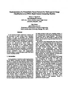
Table 1. Results for 2–tap and 4–tap transform
Table 1 presents the results of the learning process. First column shows expected percentage of input energy located on upper outputs of BOONs (i.e. b1 outputs from Figure 1c). Remaining amount of energy is located on lower outputs of BOONs, summing up to give a total of 100%. Second column shows determined rotation angle. Remaining two columns show testing result obtained on both training and testing sets, expressed as actual percentage of energy located on upper outputs of BOONs. Columns in the 4–tap section show the same information, however expected energy proportions and determined rotation angles are given for both layers of the network, while testing results are given only for output layer. Results show that network is able to achieve desired energy distribution in case of image signals, sometimes with error less than 1%.
8
Jan Stolarek and Mykhaylo Yatsymirskyy
6 Conclusion The lattice structure proposed in this paper can be characterized by the simplicity of its framework and the effectiveness of calculations. It is constructed on the basis of iterative repetition of simple two–point base operations and it can be implemented in the form of a simple pipelined scheme. As a result it gives extensive possibilities of software and hardware implementations of wavelet transforms with special indication on the integrated circuits. Within the further development of the proposed lattice structure the relation between the orthogonal lattice structure and the orthogonal wavelet transform should be investigated in detail. It means that the class of wavelet transforms that can be implemented with the orthogonal lattice structures should be defined. From the practical point of view it is crucial to develop novel training techniques of multilayer neural networks with topologies based on the proposed lattice structure.
References 1. I. Daubechies. Ten Lectures on Wavelets. SIAM, 1992. 2. M. Jacymirski and P. Szczepaniak. Neural realization of fast linear filters. In Mislav Grgi´c, editor, 4th EURASIP-IEEE Region 8 International Symposium on Video/Image Processing and Multimedia Communications, pages 153–157, 2002. 3. S. Osowski. Sieci neuronowe do przetwarzania informacji. Oficyna Wydawnicza Politechniki Warszawskiej, 2nd edition, 2006. 4. P. Rieder, J. Gotze, J. S. Nossek, and C. S. Burrus. Parameterization of orthogonal wavelet transforms and their implementation. Circuits and Systems II: Analog and Digital Signal Processing, IEEE Transactions on, 45(2):217–226, February 1998. 5. B. Stasiak and M. Yatsymirskyy. Fast orthogonal neural networks. Lecture Notes in Computer Science, 4029:142–149, July 2006. 6. K. Stokfiszewski and P. Szczepaniak. An adaptive fast transform based image compression. In Artificial Intelligence and Soft Computing, pages 874–885. Springer, 2008. 7. J. Stolarek. Realization of Daubechies transform using lattice structure. In The Collection of Scientific Works of ISDMCI 2009, volume 2, pages 188–192, 2009. 8. R. Tadeusiewicz. Sieci neuronowe. Akademicka Oficyna Wydawnicza RM, 1993. 9. P.P. Vaidyanathan and P.-Q. Hoang. Lattice structures for optimal design and robust implementation of two-channel perfect-reconstruction QMF banks. Acoustics, Speech and Signal Processing, IEEE Transactions on, 36(1):81–94, January 1988. 10. M. Yatsymirskyy. Synteza przeksztaÃlce´ n falkowych dla mobilnych system´ ow egospodarki. In Monografia : Wybrane problemy elektronicznej gospodarki, pages 273–281. 2008. 11. M. Yatsymirskyy. Lattice structures for synthesis and implementation of wavelet transforms. Journal of Applied Computer Science, 17(1):133–141, 2009.