Visual Servoing using Fuzzy Controllers on an Unmanned Aerial Vehicle Miguel A. Olivares-M´ endez
Pascual Campoy Cervera
Iv´ an Mondrag´ on
Carol Mart´ınez
Universidad Polit´enica
Universidad Polit´enica
Universidad Polit´enica
Universidad Polit´enica
de Madrid
de Madrid
de Madrid
de Madrid
[email protected]
[email protected]
mig
[email protected] [email protected]
Abstract This paper presents an implementation of three Fuzzy Logic controllers working in parallel onboard a UAV, two for a pan-tilt camera platform and the third for control the yaw of the helicopter. This implementation uses a Lucas-Kanade tracker algorithm with a pyramidal optical flow implementation, which gives information to follow statics and moving objects, besides the UAV vibrations and movements. The platform controller is helped by the heading controller, in order to make smooth the big movements to the platform, reducing the risk of lost the warp selection of the object to track. Also, the heading control remove the physic limit of the platform at the yaw axis. Some laboratory and UAV tests are presented in order to show the different behaviors and the good response of the presented controllers. Keywords: Unmanned Aerial Vehicles, Fuzzy Control, Visual servoing, pan-tilt platform.
1
Introduction
The object detection and tracking is a common problem in vision systems in all of the robotics platforms. On one hand, using Unmanned Aerial Vehicle enlarge the possible applications by the increase of the workspace
size, covering a bigger area to inspect, detect and tracking, but, on the other hand, increase the problem of visual servoing, based on the difficulties of the aircraft stabilization and control when we are trying to track an object. There are different visual algorithms in order to face this problem working with UAV, some of then are presented in [1]. For this work we use the pyramidal Lucas-Kanade optical flow implementation. The problem increase when we have not got total freedom of movements by big environment perturbations, inaccessible environments positions or unattainable objets or targets to track, as well as have a path planning desires. The uses of Fuzzy logic are growing in some fields at robotics, trying to made a better adaptation to resolve the non-linear problems of the real world. This technique give us easy, rapid and comprehensive way to create controllers by the definition of the linguistic value of its variables, base of rules and the easy way to tuning this kind of controllers, against the uses of the classical PID controllers, for what it is necessary to calculate the model of the helicopter and the visual platform. On the other hand the interest in UAVs is increasing too, based on the significant developments on UAVs fields on control architectures and the cheap and suitable alternative that it bring. Currently, some applications have been developed, among which we can find Valavanis’ works on traffic monitoring [7], and fire detection [4] or the works in obstacles avoidance and 3D path planning for UAVs by [3]. There are some tests using
a pan-tilt video-platform, like [8] based the tracking on a biomimetic Eye or the uses for a target tracking and motion estimation for moving targets by [2]. For a better comprehension we divided this paper in the next sections. In the section 2 we show a description about the UAV used in this work. Section 3 will show the Miguel Olivares’ Fuzzy Software definition and the configurations of the different fuzzy controllers. The presentation of some results obtained for this work are shown in the chapter 4 and, to finalize, we present the conclusions and the future works in section 5.
2
UAV System Description
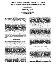
The Colibri project has three totally operative UAV platforms. One electric helicopter, and two gas powered helicopters. The COLIBRI testbeds [1], are equipped with an xscalebased flight computer augmented with sensors (GPS, IMU, Magnetometer, fused with a Kalman filter for state estimation). For this work, the most used helicopter has been the SR20 of “Rotomotion”, the electric one (figure 1).
Figure 1: COLIBRI III Electric helicopter. It includes a two axis pan-tilt video-platform powered by two servo-motors, with an action range of 180 degrees. For the control of the platform we send commands to the servos through the helicopter controller, based on the visual information acquired. To perform vision processing, it has a VIA nano-ITX 1.5 GHz onboard computer with 1 Gb RAM.
Besides the difficulties of the environment or the necessities of the pilot, giving the possibility to track an object in the next situations: 1. With a preprogrammed series of way points (path planning). 2. When flight commands are sent from the pilot radio control or from the ground station. 3. Staying in hovering position in a safe place. Some of those work modes are shown in the chapter 4.
3
3.1
Fuzzy Software Implementation
For this work we use the MOFS (Miguel Olivares’ Fuzzy Software), developed in previous works [6], [5]. This software was independently designed defining one class for each part of the fuzzy-logic environment (variables, rules, membership functions and defuzzification modes) in order to facilitate the future updates and making easier work with it. There are different classes for Depending on the system we want to create we can define the number of inputs and outputs that we prefer or make some different system in serial mode or working in parallel. One of the differences between this software and others Fuzzy software is that it lets to represent a more important sector in each fuzzy variables, giving us the possibility to reduce the size of the rule-base, that will give improve response-time and reduce the computational cost. Others differences and a more explained documentation can be consulted in [6], [5]. The MOFS is defined like a controller class inside the server program running onboard the helicopter. 3.2
The principal aim of this work is to create a suitable automatic control to the different situations or desirable solutions that we can face with a UAV with vision support. For this reason we make the fusion between control of different parts of the helicopter, the videoplatform and the heading of the helicopter.
Visual servoing using Fuzzy controllers
Fuzzy Controllers
The implementation of the task of the visual tracking control system is made with the fusion between the Lucas-Kanade tracker algorithm and three Fuzzy controllers working in parallel. Two of these controller are for the vision platform of the UAV, one for each axis
and the other is for the yaw control of the helicopter (heading). All of these controllers are implemented using the previous software definition (MOFS). We used a camera with 320x240 resolution. Getting the information of the error from -160 to 160 pixels in yaw and from -120 to 120 for the pitch axis. The fuzzification of the inputs and the outputs are defined by using a triangular membership function, for the platform controllers, and trapezoidal membership functions, for the heading. The controllers has two inputs, the error between the center of the object and the center of the image (figures 2(a) and 2(c)) and the difference between the last and the actual error (figures 2(b) and 2(d)), derivative of the position or the velocity of the object to track. The platform controllers output represents how many position must the servomotor turn, from 0 to 255, in the two axis, to minimize the error, with the same definition of the output of both (figure 3(a)). The heading controller have the same inputs of the yaw controller (figure 2(a) and 2(b)) , and the output represented how many radians must the UAV rotate to line up the object (figure 3(b)). The three controllers are working in parallel giving a redundant operation to the yaw axis, in order to reduce the error that we have with the yaw-platform controller, where the limitations of the visual algorithm and the movements velocity of the servos hinders us to take a quicker response. The other utility of this third controller is to eliminate the turn limitation of the platform when the object to track going to the back part of the UAV. All of these are guided by a 49 rules base. Defining for the output of the platform controllers a more important sector in the section near to zero, as shown in figure 3(a). This option, give us the possibility to define a very sensible controller when the error is so small, the object is very near to the center of the image, and a very quick respond controller when the object is so far. For the heading controller we defined a trapezoidal part in the middle of the output in order to help the platform controller, just when the object to track is with so far to the center of the image. With these trapezoidal
definition we get a more stable behavior of the helicopter, in the situations where the object to track is near to the center, obtaining a 0 value.
(a) Yaw Error.
(b) Derivative of the Yaw error.
(c) Pitch Error.
(d) Derivative of the Pitch error.
Figure 2: Inputs Variables of the controllers.
(a) Output of the Yaw and the Pitch
controllers.
(b) Output of the Heading controller.
Figure 3: Output Variables of the controllers.
4 4.1
Experiments Laboratory Experiments
In order to test and fit the heading controller we make some tests with the platform control, tracking a real object inside the laboratory and with a communication in real time with the simulator of the helicopter. In figure 4 is
shown the error, in pixels. The response of the heading controller is shown in figure 5, where we can see that it just response to big errors in the yaw angle of the image. Also, we can see, in figure 6, how these signals affect to the helicopter heading, changing the yaw angle in order to collaborate with the yaw controller of the visual platform.
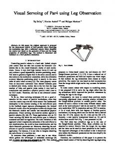
Figure 7: 3D flight reconstruction from the GPS and the center of the image, running with the UAV simulator.
and the IMU data from the UAV. Where, the ’X’ axis represents the NORTH axis of the surface of the tangent of the earth, the ’Y’ axis represents the EAST axis of the earth, the ’Z’ is the altitude of the helicopter and the red arrows show the pitch angle of the helicopter.
Figure 5: Response of the Fuzzy control for the heading of the helicopter.
(a) Pitch angle movements.
Figure 4: Error between the static object tracked
(b) Yaw angle movements.
Figure 6: Heading Response.
Figure 8: Different pitch and yaw movements of the UAV.
4.2
Tests on UAV
In this subsection we show the real tests onboard the UAV, tracking static and moving objects. For these tests we use the controllers of the visual platform. 4.2.1
Tracking Static Objects
Here a path-planning flight with a static object tracking is presented. In figure 7 is shown a 3D reconstruction of the flight using the GPS and the IMU data. The frame-rate is 15 frames per seconds, and the 2500 frames represent a real flight of almost 3 minutes. In figure 8 is shown the movements of Yaw and Pitch of the UAV, which give us a better measure about the movements and the problems to solve by the controller and the tracker for tracking and follow the mark.
In figure 10, the output of the two FuzzyMOFS controllers in order to compensate the error caused by the changes of the different movements and angle changes of the UAV flight, where we can see all the responses of the controllers, depending the sizes and the types of the perturbations.
Figure 9: Error between center of the image and center of the object to track. The table 4.2.1 shown the data of the flight. We had a maximum error in the flight, taking apart the ignition of the motor, of +100 pix-
Table 1: Data from big attitude changes sections of the flight. Section
Frames Interval
Attitude angle
Degrees
Frames Num.
Time
degrees per sec.
Pixels Error
1 1 1 1 1 1
540-595 590-595 570-595 595-620 595-660 620-660
Yaw Roll Pitch Yaw Roll Yaw
+8 -5 -4 -22 +10 +20
55 5 25 25 65 40
3.6s 0.33s 1.6s 1.6s 4.3s 2.6s
+2.28/sec -15/sec -2.5/sec -13.75/sec +2.35/sec +15.38/sec
+100 (Yaw) +100 (Yaw) +40 (Pitch) +50 (Yaw) +50 (Yaw) -75 (Yaw)
2 2
1460-1560 1560-1720
Yaw Yaw
-40 +28
100 160
6.6s 10.6s
-6.06/sec +2.64/sec
+52 (Yaw) 48 (Yaw)
3
2170-2260
Yaw
-35
90
6s
-5.8/sec
55 (Yaw)
4
2375-2450
Yaw
-27
75
5s
-5.4/sec
48 (Yaw)
Figure 10: Output from the Fuzzy Controller. els during the initial elevation of the aircraft and a maximum error of 55 pixels during the flight. The error represents a 62.2% in the initial elevation, where we have a fusion of all the possible movements and angles changes in a UAV, with a bigger change of 15.38 degrees per sec. And a 34.375% of the yaw axis of the camera, with a maximum angle change of 6.06 degrees per sec. So we can say that the controller has a good behavior solving those kind of problems.
of the to controllers, where we can see the big movements of the controller send to the servos when the warp is re-selected. We must noticed that in all of those figures that show the controller responses there are not register the data when the warp selection is deselected, because in those movements we do not made any track. We can see that the bigger response of the controllers are almost ±10 degrees for the yaw controller and almost 25 degrees for the pitch controller, being the correction in a few frames, less than 10 frames.
Figure 12: Response of the Fuzzy control for the 4.2.2
Tracking Moving Objects
Here we present a tracking of a van with continuous movements of the helicopter for increase the difficulty of the test. In figure 11 we can see the error in pixels of the two axis of the image. Also, we can see the moments where we deselected the template and re-selected it for increase the difficulty for the controller, those intervals are represented when the error remain fixed in one value for a long time. In
Yaw axis of the visual platform tracking a dynamic object (a van).
Figure 13: Response of the Fuzzy control for the Pitch axis of the visual platform tracking a dynamic object (a van).
5
Figure 11: Error between center of the image and center of the dynamic object (a van) to track.
the figures 12 and 13 we can see the response
Conclusions and Future Works
In this work we present an autonomous fuzzy control of pan and tilt video platform on board a UAV and a UAV-heading controller using a Lucas-Kanade tracker for static and moving objects. The controllers have a excellent behavior tracking static objects and
moving objects, besides the perturbations of the environments and the own vibrations of the helicopter. The use of the pan and tilt visual platform give to the helicopter a freedom of movements, as well as, a faster response with moving objects tracking, being the others implementations of visual servoing on UAV without pan and tilt platform more limited and slower than the platform servos response. With the heading controller we can made the movements of the platform a little bit soft. Also, this control implementation apport more states to work with the helicopter and tracking object giving us a lot of possible applications, because is possible to track object from a hover position due to limitations of the environments or the helicopter movements, like situations of stay near to an electric structures, fields of wind turbines or dams. Another work state is with a path planning, giving the possibility of create a reliable testbed for different controllers or visual algorithm, as well with commands sent from the pilot controller and the ground station. The principal and immediate future work is to improve the fuzzy system for a better behavior and compare with other controllers. Also now we are working for taking the up-level control of the helicopter with other FuzzyMOFS controllers that send to the UAV commands of yaw and pitch to increase the possibility to follow dynamic objects for a long time and in order to find more applications. It is possible to view the tests videos and more on the web www.disam.upm.es/colibri.
Acknowledgments This work is the product of several research stages at the Computer Vision Group Universidad Polit´ecnica de Madrid. Has been sponsored by the Spanish Science and Technology Ministry under grants CICYT DPI200406624, CICYT DPI2000-1561-C02-02 and MICYT DPI2007-66156.
References [1] P. Campoy, J. Correa, I. Mondragon, C. Martinez, M. Olivares, L. Mejias, and
J. Artieda. Computer vision onboard uavs for civilian tasks. Journal of Intelligent and Robotic Systems, 2008. [2] V. Dobrokhodov, I. Kaminer, K. Jones, and R. Ghabcheloo. Vision-based tracking and motion estimation for moving targets using small uavs. American Control Conference, 2006, pages 6 pp.–, June 2006. [3] S. Hrabar. 3d path planning and stereobased obstacle avoidance for rotorcraft uavs. Intelligent Robots and Systems, 2008. IROS 2008. IEEE/RSJ International Conference on, pages 807–814, Sept. 2008. [4] I. K. Nikolos, N. C. Tsourveloudis, and K. P. Valavanis. A uav vision system for airborne surveillance. In Robotics and Automation, 2004. Proceedings. ICRA ’04. 2004 IEEE International Conference on, pages 77–83, New Orleans, LA, USA, May 2004. [5] M. Olivares, P. Campoy, J. Correa, C. Martinez, and I. Mondragon. Fuzzy control system navigation using priority areas. In Proceedings of the 8th International FLINS Conference, pages 987–996, Madrid,Spain, September 2008. [6] M. Olivares and J. Madrigal. Fuzzy logic user adaptive navigation control system for mobile robots in unknown environments. Intelligent Signal Processing, 2007. WISP 2007. IEEE International Symposium on, pages 1–6, Oct. 2007. [7] A. Puri, K. Valavanis, and M. Kontitsis. Statistical profile generation for traffic monitoring using real-time uav based video data. In Control and Automation, 2007.MED ’07. Mediterranean Conference on, MED, pages 1–6, 2007. [8] H. Zou, Z. Gong, S. Xie, and W. Ding. A pan-tilt camera control system of uav visual tracking based on biomimetic eye. Robotics and Biomimetics, 2006. ROBIO ’06. IEEE International Conference on, pages 1477–1482, Dec. 2006.