Feature Extraction and Detection of Simple Objects Using Particle Swarm Optimisation Mahdi Setayesh
Mengjie Zhang
Mark Johnston
School of Mathematics, Statistics and Operations Research Victoria University of Wellington
[email protected], New Zealand
[email protected] School of Engineering and Computer Science Victoria University of Wellington Wellington, New Zealand
School of Engineering and Computer Science Victoria University of Wellington Wellington, New Zealand
[email protected]
ABSTRACT The purpose of this paper is to demonstrate the application of particle swarm optimisation to the detection of simple objects. The paper’s new contribution to object detection is application of particle swarm optimisation for extraction of geometric properties of an object in an image for accurate recognition especially in noisy environments. In this approach, the edges and the corners of an object are detected by particle swarm optimisation algorithm and then the object is classified based on number of the corners and attributes of the edges by a simple fuzzy rule-based classifier. Several simple geometric objects in different aspects have been used in the variety of noise levels for testing of the system. This system can categorise images containing these simple objects even with high noise levels more accurately in contrast to other approaches proposed in the last literature.
Categories and Subject Descriptors I.4 [Image Processing And Computer Vision]: Miscellaneous
General Terms Algorithms
Keywords Particle swam optimisation, computer vision, object detection, edge detection, corner detection, simple fuzzy classifier
1.
INTRODUCTION
Particle Swarm Optimization (PSO) is a recent computational intelligence method, Introduced by Kennedy and Eberhart in 1995 [6]. PSO is a population-based evolutionary algorithm for problem solving based on social-psychological
principles. Before evolution, an initial population of individual particles are randomly generated as candidate solutions. An iterative evolutionary learning process to improve these candidate solutions is set in motion. The learning process iteratively evaluates the goodness/fitness of the candidate solutions and remembers the locations of the individual particles where they had their best success. The individual’s best solution is called the local best. Each particle makes this information available to their neighbors. They can also see where their neighbors have had success. Movements through the search space are guided by these successes, with the population usually converging, by the end of the evolution, on a global best solution. Although relatively new compared with other AI methods such as neural networks and genetic algorithms, PSO is considered particularly suitable to optimising a large number of parameter values efficiently, which could provide a great potential to edge and corner detection where many pixel positions need to be found. To date, PSO has been used in a number of vision applications such as object detection, object classification and segmentation [3], but has not applied to feature extraction like edge and corner detection directly. This paper presents a system that uses PSO technique to extract the features of an image like its edges and corners and then apply a fuzzy rule-base classifier to detect the interesting object. The main goal in this paper is to detect and identify simple shapes like square, rectangle, triangle ,cross and circle in different aspects. The final goal of the ongoing research is to develop the system to use for generic detection of complex objects like the airplane, the pedestrian and the car.
1.1 Goals The goal of this paper is to investigate a new approach to the use of PSO technique for the feature extraction. In this paper, the geometric attributes of an image is used by the system to recognise the object. The geometric attributes extracted by the proposed system are the edges and the corners in the image. Rather than using a simple track of a particular pixel with its neighbors at a time as in many existing edge and corner detection operators, the new approach aims to operate on the entire possible edges and corners at a time and improve the possible solution via the automatic evolutionary learning in PSO. In addition, we would like the proposed system to achieve good performance for simple and regular edges and corners as well as detecting edges and cor-
ners on noisy environment. This system will be examined and compared with proposed approach in [7]. Specifically, we would like to investigate the following research objectives. • How the individual particles can be formed for extracing the entire corners and edges of possible objects or regions; • How the fitness/objective function can be established in PSO for evaluating the individual particles (possible candidate solutions) in the population for edge and corner detection; • Whether the new approach can perform well on detecting edges and corners of simple objects, objects with noise without any preprocessing or postprocessing • Whether the system can use the extracted features to detect the simple objects The rest of the paper is organised as follows. Section 2 provides some essential background, including a brief discussion of particle swarm optimisation followed by an abstract of computer vision. The new approved PSO-based edge detection, corner detection algorithms and the architecture of the system are described in Section 3. Experimental setup and results are presented in Section 4. Section 5 gives the conclusion with some future research directions.
2.
BACKGROUND
This section describes required background information for object detection and particle swarm optimisation.
2.1 Particle Swarm Optimisation A formal definition of the PSO algorithm is presented in this section, as proposed by Kennedy and Eberhart [6]. Each individual particle i in a population has the following properties: a current position in search space, xi , a current velocity, vi , and a personal best position in search space, yi . The personal best solution yi , corresponds to the position in search space where particle i had the smallest error as determined by the objective function f . The position yielding the lowest error amongst all the yi is called the global best position and is denoted y ′ . Equations (1) and (2) define how the personal and global best values are updated, respectively. It is assumed below that the swarm consists of s particles, thus i ∈ {1, ..., s}.
yi (t + 1) =
yi (t) xi (t + 1)
if if
f (xi (t + 1)) ≤ f (yi (t + 1)) f (xi (t + 1)) > f (yi (t + 1)) (1)
y ′ (t) ∈ {y0 (t), y1 (t), ..., ys (t)} f (y (t)) = min{f (y0 (t)), f (y1 (t)), ..., f (ys (t))} ′
nature of the algorithm. For all dimensions j ∈ {1, ..., n}, let xi,j , yi,j and vi,j be the current position, current personal best position and velocity of the j th dimension of ith particle. The purpose of the inertia weight w and the constants c1 and c2 are discussed in more detail below. The velocity update step is:
vi,j (t + 1) = wvi,j (t) + c1 r1,j (t)[yi,j (t) − xi,j (t)]+ c2 r2,j (t)[yj′ (t) − xi,j (t)]
(3)
The new velocity is then added to the current position of the particle to obtain the next position of the particle:
xi (t + 1) = xi (t) + vi (t + 1)
(4)
The value of each dimension of every velocity vector vi is clamped to the range [−vmax , vmax ] to reduce the likelihood of the particle leaving the search space. The value of vmax is usually chosen to be k ×xmax , with 0.1 ≤ k ≤ 1.0 [16], where xmax denotes the domain of the search space. Note that this does not restrict the values of xi to range [−vmax , vmax ]; it merely limits the maximum distance that a particle will move during one iteration. The inertia weight w, in equation (3) is used to control the convergence behavior of the PSO. The small values of w result in more rapid convergence usually on a suboptimal position, while a too large value may prevent convergence. Typically implementations of the PSO adapt the value of w during the training run, e.g., linearly decreasing it from 1 to near 0 over the run. Convergence can be obtained with fixed values as shown in [16]. The acceleration coefficients, c1 and c2 , control how far a particle will move in a single iteration. Typically these are both set to a value of 2.0, although it has been shown that setting c1 6= c2 can be lead to improved performance [10].
2.2 Computer Vision Computer vision is probably the most exciting branch of image processing, and the number of applications in robotics, automation technology and quality control is constantly increasing [1]. As a technological discipline, computer vision seeks to apply its theories and models to the construction of computer vision systems. Examples of applications of computer vision include systems for controlling processes (e.g., an industrial robot or an autonomous vehicle), detecting events (e.g., for visual surveillance or people counting), organizing information (e.g., for indexing databases of images and image sequences), modeling objects or environments (e.g., industrial inspection, medical image analysis or topographical modeling), interaction (e.g., as the input to a device for computer-human interaction) [4].
(2)
During each iteration each particle in the swarm is updated using equations (3) and (4). Two pseudo-random sequences, r1 ∼ U (0, 1)and r2 ∼ U (0, 1) are used to effect the stochastic
Computer vision is a research area with many effective approaches for image processing, including feature detection and object recognition. While these methods are used to extract features, they all need computationally complicated structures and operations that introduce performance and
scalability problems. In addition, most of these methods are indifferent to the underlying meaning and boundaries of analyzed regions, and do little to reduce the complexity of the output data [7]. A common method for feature extraction involves assigning each pixel a level of belonging to a region or group [2]. While this may accurately allow for the characterization of fixed regions, it does not provide insight into the underlying nature of the area such as its general geometry and characteristic features. This is a capability lacking in most current approaches. Through extraction of an object’s key features, it is possible to create a simplified representation of the object that is compatible with a suitable classification system. By extracting and utilizing geometric properties of an image, it is possible to reduce the complexity of the image’s representation as seen at the input of the classification system. This results in a significant decrease in the computational complexity required to analyze object data, without degrading the accuracy of the results. The approach proposed in this paper uses a system to simplify a image into a list of geometric properties such as the edges and their orientations, the number of the corners and their anlges. This kind of image representation is suitable for analysis by a classifier system, such as a rule based system.
2.2.1 Edge Detection Approaches Edge detection refers to the process of identifying and locating sharp discontinuities in an image. The discontinuities are abrupt changes in pixel intensity which characterise boundaries of objects in a scene. Classical methods of edge detection involve convolving the image with an operator (a 2D filter), which is constructed to be sensitive to large gradients in the image while returning values of zero in uniform regions. There are an extremely large number of edge detection operators available, each designed to be sensitive to certain types of edges. Variables involved in the selection of an edge detection operator include [3]: • Edge orientation: the geometry of the operator determines a characteristic direction in which it is most sensitive to edges. Operators can be optimised to look for horizontal, vertical, or diagonal edges. • Noisy environment: edge detection is difficult in noisy images, since both the noise and the edges contain high-frequency content. Attempts to reduce the noise often result in blurred and distorted edges. Operators used on noisy images are typically larger in scope, so they can average enough data to discount localised noisy pixels. This results in less accurate localization of the detected edges.
best edge detection technique for an application is [18]. The simplest and quickest edge detectors determine the maximum value from a series of pixel subtractions. A popular edge detection algorithm is the homogeneity operator which subtracts each eight surrounding pixels from the center pixel of a 3×3 window as in figure 1.
Figure 1: Homogeneity operator. The homogeneity operator can be formulated as below:
HP =
max({|IP − INi |i = 1 . . . 8}) if > threshold 0 otherwise (5)
where P is particular pixel which we are going to calculate HP . Ni is ith neighborhood of pixel P. In this equation, IP is the intensity of pixel P. Threshold is a number between 0 and 255 which can be specified by the user.
2.2.2 Corner Detection as Interest Point Detection In computer vision general terminology, the corner is defined as a interst point that is created through intersection of two or more edges. There are a lot of approaches proposed in the literature (e.g. ,The Moravec [9], Harris and Stephens [5], the multi-scale Harris [], Shi and Tomasi [13], the level curve curvature [8], SUSAN [14] and FAST [15] corner detection algorithms) but most of them need complicated computations and some of them are poor in detection rate, localization, repeatability rate, robustness to noise and speed aspects [17].
3. PARTICLE SWARM OPTIMISATION FOR OBJECT DETECTION
• Edge structure: not all edges involve a step change in intensity. Effects such as refraction or poor focus can result in objects with boundaries defined by a gradual change in intensity. The operator needs to be chosen to be responsive to such a gradual change in those cases. There are many edge detection techniques and each of them has its own strength and weakness. Some edge detectors may work well in one application and perform poorly in others. Sometimes it takes experimentation to determine what the
Figure 2: PSO-based object detection system architecture As shown in Figure 2, our proposed system is composed by three main parts containing PSO-based edge detection,
PSO-based corner detection and fuzzy rule-based classifier. we introduced a PSO-based edge detection algorithm in our previous paper that in this research, we try to improve it to detect the edges of an image much better than previous algorithm. The PSO-based corner detection that introduced in this paper, can detect the corners of an image more accurately specially in noisy environments like our edge detection algorithm. after extraction of the corners and the edges of an image, we use a simple fuzzy rule-based classifier to detect the object in this image based on number of the corners and their angle and number of edges and their orientations. The rest of this paper will describe main parts of this system in detail.
3.1 PSO-Based Algorithm for Edge Detection Considering that the best edge is a collection of pixels which are on a curve, we proposed a new edge detection algorithm which finds the best fitting curves on important edges of objects in an image in [12]. In order to find curves on an object’s edges, we used a PSO-based algorithm to detect these curves. This algorithm is applied for each pixel in an image to detect the best curve which can be fitted on the edges in an image and passes through a pixel. To find the best fitting curve that passes through a pixel and all points on it corresponding to pixels on edges, we introduced a new PSO-based algorithm where each particle represents a curve. In the ideal case, the result of applying an edge detector to an image may lead to a set of connected curves that indicate the boundaries of objects, the boundaries of surface markings, as well as curves that correspond to discontinuities in surface orientation. Many edge detection algorithms act as a convolution matrix and are applied just on one pixel and its neighbors like Sobel and Kirish operators, whereas edges on an image are a collection of pixels which are recognized as an edge. Our new edge detector uses PSO for detection of best available important curves in an image that represent boundaries of objects. we introduced two new measures, homogeneity and uniformity factor of a curve, that are used to form the objective function of the PSO based edge detection algorithm. The results showed that the proposed algorithm performs better than Sobel and the homogeneity operators and that it can be applied to noisy images without using any filtering algorithms.
3.2 Encoding of Edges as a Particle In each particle of this algorithm, the value of each attribute is an integer in the range 0 to 8, and these values represent the direction of the movements on a curve which is encoded as a particle. Each particle in the PSO population can be shown as hd1 , d2 , ..., dmax i, where di is a number between 0 and 8, and max is the maximum number of pixels on a curve. For example, suppose that there is a curve passing through a point corresponding with a pixel on an image as it has been shown in figure 3. In figure 3, there is a curve passing through pixel A. We can encode this curve as a particle using the direction of the movement from a pixel to the next pixel on the curve which has been shown in figure 3. In other words, each attribute value of a particle represents the direction number of the
Figure 3: An example for a curve passing through pixel A.
Figure 4: Particle encoding for the curve in figure 3.
movement on the curve based on arrows numbers shown in figure 1. Hence our particle for representing this curve will be as figure 4. The dimension of the vector representing a particle depends on the image size. If the number of pixels on a curve is less than the dimension of a particle, remaining cells will set to zero as in figure 4.
3.2.1 Two New Factors A large number of pixels on an edge of an image have the same or similar intensity. On the other hand, the homogeneity of these pixels must be larger than the homogeneity of the pixels which are not on an edge. Therefore, we introduce two new factors of a curve, the homogeneity and uniformity factors. The first one measures the homogeneity of the pixels on a curve and the second one measures the intensity similarity of these pixels.
• Homogeneity factor of a curve: now we introduce a new concept that we call it the homogeneity factor of a curve. This factor shows the average of homogeneity of the pixels on a curve where the homogeneity of each pixel on the curve is calculated based on equation (5). This factor is defined as below:
HC =
1 X HPi LC P ∈C
(6)
i
where Pi is ith pixel on the curve C and LC is the length of a curve C that can be calculated by following equation: X 1 if √ LC = 2 if Pi ∈C
dPi dPi
is odd is even
(7)
HPi can be calculated by using equation (5). We will use this factor in the definition of the PSO objective function. • Uniformity factor of a curve: The pixels on a curve often have similar values of intensities; hence we introduce a new concept that we call the uniformity factor of a curve. This factor can be computed for any curve as below:
UC =
Lc −1 1 X |IPi+1 − IP | LC i=1
(8)
We will use this factor in the definition of the PSO objective function required in our algorithm.
3.3 Objective Function of PSO-based Edge Detection algorithm The basic PSO algorithm needs an objective function like any optimization problem as discussed in Section II. We propose an objective function as equation (9) that it is based on the uniformity and homogeneity factors discussed before. In this problem, we search the curves which pass through a pixel. We expect to make the homogeneity factor bigger, the uniformity factor smaller, and the length of the curves bigger. So we heuristically define this function as below:
fC =
−∞ (HC − UC ) × LC
HC < T hreshold (9)
Algorithm 1 Pseudo code for proposed edge detection algorithm 1: For each pixel P on an image do 2: If P is not marked as an edge then 3: Initialize PSO population randomly for pixel P 4: Repeat 5: For each particle do 6: Decode the particle as curve C 7: Evaluate HC and UC and LC according to (6) and (8) and (7) 8: Evaluate fC based on (9) 9: If fC is better than the best fitness value then 10: Set current value as the new best particle 11: End if 12: End For 13: For each particle do 14: Find in the particle neighborhood, local best particle 15: Calculate particle velocity according to (3) 16: Apply the velocity constriction 17: Update particle position according to (4) 18: Apply the position constriction 19: End for 20: Until maximum iterations exceeded or minimum error criteria attained 21: Select best particle in the population and decode it as curve C 22: Evaluate as length of curve C 23: If LC > M inL then 24: Mark all pixels on curve C as an edge 25: End if 26: End if 27: End For
HC ≥ T hreshold
3.4.1 Particle Encoding for Corner Detection Here fC is the objective function value for the curve C encoded as a particle. Our PSO algorithm maximises fC to find the best fitting curve which passes through a pixel. If the curve C crosses itself, the value of fC must be evaluated negative infinity.
3.3.1 New Edge Detection Algorithm The pseudo code of our PSO based edge detection for finding the best fitting curve passing through a pixel is shown in Algorithm 1. In this algorithm, M inL is the minimum length of a curve in an image. This parameter has the effect of removing available noise in an image. This algorithm uses the basic PSO with the objective function and encoded particles discussed earlier.
3.4 New PSO-Based Algorithm for Corner Detection As system architecture shown in figure 2, after applying of edge detection Algorithm 1, we should use another algorithm to detect the corners of an image. According to that PSObased edge detection algorithm marks all present edges on an image, PSO-based corner decetion algorithm proposed in this section, tries to find all corners which is created by two or more detected edges.
Each corner is composed by two or more curves that intersect eachother in one point. Therfore, in each particle of this algorithm, we need to encode two curves that they make a corner together. In this method of encoding, maximum length of each curve is seven so length of each particle will be fourteen. The value of each attribute of a particle is an integer in the range 0 to 8, and these values represent the direction of the movement on two curves which create a corner. Each particle in the PSO population can be presented as hd1 , d2 , ..., di , ..., d14 i, where di is a number between 0 and 8. For example, consider that there is a corner on an image as it has been shown in figure 5. In figure 5, there are two curves in two different direction (direction 1 and direction 2) that they intersect eachother in the red point. Attribute numbers from 1 to 7 indicate the curve in direction 1 and attributes numbers from 8 to 14 indicate the curve in direction 2. Therefore, the particle for representing this corner will be like figure 6. The dimension of the vector representing a particle can be variable according to the image size and interesting accuracy of the algorithm.
3.4.2 Objective Function of PSO-based Corner Detection algorithm Our PSO-based corner detection algorithm like PSO-based edge detection algorithm requires an objective function. We propose an objective function as equation (10):
dy d i
8 > :1
di = 0, 1, 2 di = 3, 7 di = 4, 5, 6
(14)
For example, we can calculate these partial differntials for the curves shown in figure 5. The results of calculation will be as following:P dydirection1 = ∀ di ∈Cdirection dydi = 0 + 1 + 0 + 1 + 1 + 1 1+1 = 5 P dydirection2 = ∀ di ∈Cdirection dydi = 0 + 1 + 0 + 1 + 1 + 2 1+1 = 5 P dxdirection1 = ∀ di ∈Cdirection dxdi = −1 − 1 − 1 − 1 − 1 − 1 1 − 1 = −7 P dxdirection2 = ∀ di ∈Cdirection dxdi = 0 + 1 + 0 + 1 + 1 + 2 1+1 = 5 5 gradient1 = −7 , gradient2 = 55 = 1 5 −1
Figure 5: An example for a corner composed by two curves
Θ = tang −1 ( 1+−75
−7
×1
) = −80.53◦
The pseudo code of our PSO-based edge detection for detection of the corners is shown in Algorithm 2.
Figure 6: Particle encoding for the corner in figure 5.
fcorner
( |Θcorner | = −∞
10 ≤ |Θcorner | ≤ 170 otherwise
(10)
In this equation, Θ is the measure of angle between two curves that make corner. To calculate Θ, we need to compute the gradient of two curves. The gradient of a curve can be calculated by equation (11).
P
gradienti = P
∀ di ∈Cdirection
i
∀ di ∈Cdirection i
dydi dxdi
gradient1 −gradient2 Θ = tang −1 ( 1+gradient ) 1 ×gradient2 gradient1 > gradient2
(11)
(12)
In equation (11), gradient1 and gradient2 are the gradients of two curves, Cdirection1 and Cdirection2 in direction one and two that have been shown in figure 5. dx and dy are partial differntials of two curves that can be calculated by equations (13) and (14) as shown in the following:
dx d i
8 > :1
di = 0, 6, 7 di = 1, 5 di = 2, 3, 4
(13)
Algorithm 2 Pseudo code for proposed corner detection algorithm 1: For each edge E detected by Algorithm 1 on an image do 2: Initialize PSO population randomly for the edge E 3: Repeat 4: For each particle do 5: Decode the particle as corner 6: Evaluate gradient1 and gradient2 according to (11) 7: Evaluate Θcorner according to (12) 8: Evaluate fcorner based on (10) 9: If fcorner is better than the best fitness value then 10: Set current value as the new best particle 11: End if 12: End For 13: For each particle do 14: Find in the particle neighborhood, local best particle 15: Calculate particle velocity according to (3) 16: Apply the velocity constriction 17: Update particle position according to (4) 18: Apply the position constriction 19: End for 20: Until maximum iterations exceeded or minimum error criteria attained 21: Select best particle in the population and decode it as a corner and mark it as a corner 22: End For
3.5 Simple Fuzzy Rules-Based System for Detection of Simple Objects The fuzzy rule-based system has been choosed for first step of the implementation of the system, because of its simplicity to design and implement. The system has been designed based on Mamadani form of fuzzy inference system proposed in [11]. The system classifies the shapes based on extracted geometric attributes from the image. extracted geometric
attributes include number of pixels on horizontal, vertical and diagonal edges separately and also number of corners that be found in an image by use of edge and corner detection algorithms shown in previous subsection. The rules desinged to classify the objects have following form:
(a) (b) (c) (d) (e)
IF NC ≈ 12 THEN the object is a cross IF NC ≈ 4 and Θ for all corners ≈ 90 THEN the object is a rectangle IF the object is rectangle and number of edges in differentFigure 8: Some noisy images used in the system to directions are almost equal or zero THEN the object is square test IF NC ≈ 3 THEN the object is a triangle IF NC ≈ 0 and number of edges in different directions are almost equal THEN the object is a circle
In these fuzzy rules, NC is the number of corners detected by the algorithm. This system applies these rules to the input parameters (information of the corners and the edges) and classifies the simple objects. Fuzzy membership functions used in this system are triangular because they are easily designed and implemented.
4.
(a)
(b)
(c)
(d)
EXPERIMENTAL RESULTS
The parameter values of the PSO based edge and corner detection algorithm used in this paper are the same as in [12].
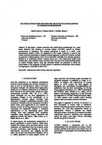
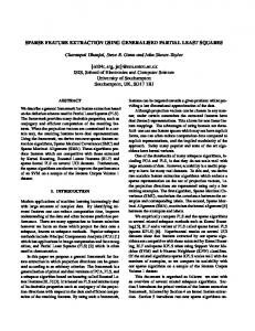
4.1 Test Image Sets We test the system on images containing five variant kind of simple shapes (square, circle, cross, rectangle, triangle) in different location, scale and orientation and in ten different black and white noise levels(0, 10, 20, ..., 90%). The image set includes 5000 images that theirs size is 256×256. Some of them has been shown in figure 7.
Figure 9: The results of the PSO-based algorithm for edge detection. a) the edges of a cross in an image with 10% noise; b) the edges of a cross in an image with 30% noise; c) the edges of a circle in an image with 10% noise; d) the edges of a circle in an image with 30% noise without any preprocessing even in noisy enviroments accurately.
Figure 7: Simple shapes used in the system to test Each shape is tested in ten different noise levels . Examples of the noisy images containing circle and cross, has been shown in figure 8.
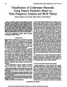
4.2 Results Figure 9 shows the resulting images by applying the PSObased edge detection algorithm on four images of the test image set in different noise levels and as it is observed, our algorithm can detect the edges well without any preprocessing even in noisy enviroments and remove automaticallythe noise. Figure 10 shows the resulting images by applying the PSObased corner detection algorithm on the same images and as it is observed, our algorithm can detect the corners well
Table 4.2 shows classification rates for the detection of the interesting simple objects. As it is observed, the system can be classify well the objects in different location, scale and orientation without any noise. In view of the fact that, representaion of small circles in digital images are difficult so it makes hard to recognise the circular objects for this system. As shown in table 4.2, classification rate for the circle is 0.98 in none-noisy images. The performance of the system is acceptable for images with noise level less than 30% but it reduces with increment of the noise level gradually.
5. CONCLUSIONS In this paper, a PSO-based approach to the detection of the simple objects has been proposed. This goal was successfully achieved by introducing a new PSO-based edge and corner detection and performance of the system was tested by recognition of the simple objects in different noise levels and
[3]
(a)
(b) [4]
[5]
[6] (c)
(d) [7]
Figure 10: The results of the PSO-based algorithm for corner detection. a) the corners of a cross in an image with 10% noise; b) the corners of a cross in an image with 30% noise; c) a circle without any corner in an image with 10% noise; d) the corners of a triangle in an image with 10% noise
[8]
[9] Table 1: Classification rates for object detection in noisy environments. Noise Rectangle Cross Triangle Circle Square 0% 1 1 1 0.98 1 10% 1 1 1 0.92 1 20% 1 1 1 0.90 0.92 30% 1 1 1 0.86 0.84 40% 0.9 0.81 1 0.77 0.72 50% 0.75 0.64 0.81 0.69 0.63 60% 0.69 0.50 0.62 0.71 0.52 70% 0.55 0.31 0.49 0.57 0.45 80% 0.47 0.17 0.33 0.46 0.39 90% 0.4 0 0.25 0.4 0.31
compared with the system proposed in [7]. The results show that our system outperforms the system proposed in [7]. In addition, our system can detect simple objects in noisy images without using any preprocessing and post processing algorithms. But, the current version of the system takes a relatively longer time than swarm-based system proposed in [7]. We will further investigate new ways of overcome this limitation in the future. The final goal of the ongoing research is to develop the system to use for generic detection of complex objects like the airplane, the pedestrian and the car.
6.
REFERENCES
[1] P. Azad, T. Gockel, and R. Dillmann. Computer Vision - Principles and Practice. Elektor International Media BV, 2008. [2] C. Bourjot, V. Chevrier, and V. Thomas. How social spiders inspired an approach to region detection. In AAMAS ’02: Proceedings of the first international joint conference on Autonomous agents and
[10]
[11] [12]
[13]
[14]
[15] [16]
[17]
[18]
multiagent systems, pages 426–433, New York, NY, USA, 2002. ACM. S. Cagnoni, M. Mordonini, and J. Sartori. Particle swarm optimization for object detection and segmentation. In Proceedings of the 2007 EvoWorkshops 2007 on EvoCoMnet, EvoFIN, EvoIASP,EvoINTERACTION, EvoMUSART, EvoSTOC and EvoTransLog, pages 241–250, Berlin, Heidelberg, 2007. Springer-Verlag. D. A. Forsyth and J. Ponce. Computer Vision: A Modern Approach. Prentice Hall, us ed edition, August 2002. C. Harris and M. Stephens. A combined corner and edge detector. In Proceedings of the 4th Alvey Vision Conference, pages 147–151, 1988. F. Kennedy, R. Eberhart, and Y. Shi. Swarm intelligence. Morgan Kaufmann, San Francisco, CA, 2001. T. Mirzayans, N. Parimi, P. Pilarski, C. Backhouse, L. Wyard-scott, and P. Musilek. A swarm-based system for object recognition. Neural Network World, 15:351–365, 2005. F. Mohanna and F. Mokhtarian. Performance evaluation of corner detection algorithms under similarity and affine transforms. In BMVC, 2001. H. P. Moravec. Visual mapping by a robot rover. In International Joint Conference on Artificial Intelligence, pages 598–600, 1997. K. Nakamatsu and J. Minoro Abe, editors. Advances in Logic Based Intelligent Systems - Selected Papers of LAPTEC 2005, Himeji, Japan, April 2-4, 2005, volume 132 of Frontiers in Artificial Intelligence and Applications. IOS Press, 2005. S. S. S. N. Sivanandam and S. N. Deepa. M. Setayesh, M. Zhang, and M. Johnston. A new homogenity-based approach to edge detection using pso. In Proceeding of the 24th International Conference on Image and Vision Computing, pages 231–236. IEEE Press, 2009. J. Shi and C. Tomasi. Good features to track. In 9th IEEE Conference on Computer Vision and Pattern Recognition. S. M. Smith and J. M. Brady. Susan—a new approach to low level image processing. Int. J. Comput. Vision, 23(1):45–78, 1997. M. Trajkovic and M. Hedley. Fast corner detection. Image and Vision Computing, 16(2):75–87, 1997. F. van den Bergh and A. Engelbrecht. A new locally convergent particle swarm optimiser. In Systems, Man and Cybernetics, 2002 IEEE International Conference on, volume 3, pages 6 pp. vol.3–, Oct. 2002. Z. Zheng, H. Wang, and E. Teoh. Analysis of gray level corner detection. Pattern Recognition Letters, 20:149–162, 1999. D. Ziou and S. Tabbone. Edge detection techniques an overview. International Journal of Pattern Recognition and Image Analysis, 8:537–559, 1998.