Int. J. Biometrics, Vol. 1, No. 1, 2008
Fingerprint image: pre- and post-processing M. Usman Akram*, Anam Tariq and Shoab A. Khan Department of Computer Engineering College of Electrical and Mechanical Engineering National University of Science and Technology (NUST) Rawalpindi, Pakistan E-mail:
[email protected] E-mail:
[email protected] E-mail:
[email protected] *Corresponding author
Sarwat Nasir Department of Telecommunication College of Signals National University of Science and Technology (NUST) Rawalpindi, Pakistan E-mail:
[email protected] Abstract: Automatic Fingerprint Identification Systems (AFIS) are widely used for personal identification due to uniqueness of fingerprints. Minutiaebased fingerprint matching techniques are normally used for fingerprint matching. Fingerprint matching results and their accuracy depends on presence of valid minutiae. In this paper, we present a new technique for fingerprint image post-processing. This post-processing is used to eliminate a large number of false extracted minutiae from skeletonised fingerprint images. We propose a windowing post-processing method that takes into account the neighbourhood of each minutia within defined window and check for minutia validation and invalidation. We also present a complete pre-processing system including new segmentation technique that is required to extract region of interest (ROI) accurately from a fingerprint image. The results are confirmed by visual inspections of validated minutiae of the FVC2004 reference fingerprint image database. Experimental results obtained by the proposed approach show efficient reduction of false minutiae. Keywords: pre-processing; feature extraction; false minutiae; windowing technique; valid minutiae; post-processing; fingerprint biometric identification; invalid minutiae elimination; Automatic Fingerprint Identification Systems; AFIS; fingerprint enhancement. Reference to this paper should be made as follows: Akram, M.U., Tariq, A., Khan, S.A. and Nasir, S. (2008) ‘Fingerprint image: pre- and post-processing’, Int. J. Biometrics, Vol. 1, No. 1, pp. 63–80. Biographical notes: Muhammad Usman Akram is currently an undergraduate student in the Computer Engineering Department, University of Science and Technology (NUST), Pakistan. His research interests include fingerprint recognition, biometrics study, image processing, pattern recognition, and signal processing. Copyright © 2008 Inderscience Enterprises Ltd.
63
64
M.U. Akram, A. Tariq, S.A. Khan and S. Nasir Anam Tariq is currently an undergraduate student in the Computer Engineering Department, University of Science and Technology (NUST), Pakistan. Her fields of interests include fingerprint recognition, image processing, and signal processing. Dr. Shoab Ahmed Khan received his PhD in Electrical and Computer Engineering from Georgia Institute of Technology. He is an Associate Professor of Computer Engineering at the College of E&ME, NUST, Pakistan. His research interests include signal processing, VLSI, ad hoc networks, sensor area networks and image processing. Sarwat Nasir received her BE Telecom degree from the University of Science and Technology, Pakistan in 2004 and her MS Electrical Engineering degree from the same institute in 2007. Her research interests include signal processing, biometrics study, image processing, and pattern recognition.
1
Introduction
The unchangeability of fingerprints during the human life span and the uniqueness of each individual’s fingerprints are the basis for using fingerprints for identification purposes (Maltoni et al., 2003). Fingerprint-based recognition is most popular among the biometric-based security systems due to the uniqueness and invariability of fingerprint feature and the feasibility of fingerprint verification system (Maltoni et al., 2003). Most automatic fingerprint identification systems (AFIS) are based on local ridge features, known as minutiae (Maltoni et al., 2003). Identification can be easily done by distinct fingerprints of a person (Maltoni et al., 2003). Small portions of fingerprints are processed using complex algorithms in AFIS (FBI, 1984). 13 types of minutiae are used like empty cell, ridge ending, ridge fork, island, dot, broken ridge, bridge, spur, enclosure, delta, double fork, trifurcation, and multiple events (Osterburg et al., 1977). Four main groups of minutiae are categorised by American National Standard Institute i.e., terminations, bifurcations, crossovers, and undetermined, which is a combination of two fundamental features known as ridge endings and bifurcations (minutiae). Ridge ending or termination is defined as the point where a ridge ends abruptly, and bifurcation is the point where a ridge diverges into branches (Maltoni et al., 2003). The minutia location and orientation can be uniquely determined using least squares method by taking a gray-scale minutiae image (Andrew et al., 2002). Usually, minutiae are extracted from thinned image (Maltoni et al., 2003). Most of the thinning algorithms may cause a spurious ridge bifurcation in fingerprint images. The feature extraction algorithms produce errors where some true minutiae are dropped and some false minutiae are inserted. Therefore, the performance of AFIS critically depends on the proper detection of minutiae from the fingerprint image (Hong and Jain, 1997). A direct gray-scale ridge line tracking strategy is presented in Maio and Maltoni (1997). Ridge-based method for minutiae filtering and methods to eliminate spurious minutiae are given in Farina et al. (1999). The AFIS proposed in Stosz and Alyea (1995) uses syntactic processing to remove unwanted artefacts, i.e., two disconnected ridges are connected if their distance is less than a given threshold and endpoint directions are almost the same and wrinkles are
Fingerprint image: pre- and post-processing
65
identified by analysing information on neighbouring branch points. A three-step false minutia identification process is adopted in Chen and Kuo (1992): 1
it repaired ridge breaks using the ridge directions close to the minutiae
2
short ridges minutiae are dropped
3
crowded minutiae in a noisy region are dropped.
False minutiae which are caused by noise or imperfect image processing are eliminated by a method described in Malleswara (1976). A binarised image post-processing technique was proposed in Fitz and Green (1996). Spikes caused by the skeletonising process are removed by the adaptive morphological filter proposed by Ratha et al. (1995). In this paper, fingerprint image pre-processing is highlighted first and then appropriate features were extracted. Pre-processing techniques mainly include: segmentation which refers to the separation foreground from the image background (Maltoni et al., 2003; Yanowitz and Bruckstein, 1989); normalisation is used to standardise the image values in a particular range; orientation field estimation is done to estimate the coordinates of ridges and valleys in a local neighbourhood (Hong et al., 1998); frequency estimation is done to model ridges and valleys in sinusoidal shape; Gabor filtering is done to remove the undesired noise and to preserve true ridges in an image (Yang et al., 2003); binarisation is done to convert gray-scale image to a binary one; and finally, thinning is done to get a skeletonised image. Then we apply a feature extraction technique, a crossing number method, to extract the minutiae from a fingerprint image. We present a new windowing technique for false minutiae elimination. Our technique detects and removes false minutiae including spikes, holes, bridges, ladder and spurs. Our proposed technique decides that a candidate minutia is valid or not depending on its neighbouring pixel values. Experimental results show the significance of our post-processing algorithm applied to minutiae extracted from a fingerprint image which is first pre-processed by the presented pre-processing technique. This paper is organised in five sections. Section 2 presents the steps for pre-processing and feature extraction from fingerprint images. Section 3 contains the proposed technique for fingerprint post-processing. Experimental results of our technique are discussed in Section 4 followed by conclusion in Section 5.
2
Pre-processing and feature extraction
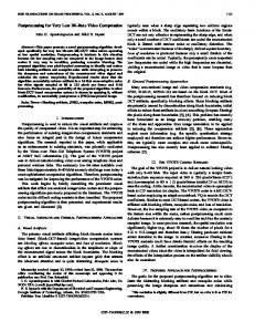
Pre-processing of fingerprint image means enhancing the fingerprint image using segmentation, orientation field estimation and applying filters like Gabor filters for fingerprint image enhancement (Maltoni et al., 2003). This enhancement is required so that the thinned image has very little spurious ridges and to reduce the probability of false minutiae extraction. And feature extraction means extraction of minutiae from a thinned image (Maltoni et al., 2003). Figure 1 shows the complete flow of pre-processing and feature extraction. The original image first undergoes enhancement procedure. Enhancement process includes segmentation (separating background from foreground), normalisation of an image (standardisation of the dynamic levels of variation in gray-level values), orientation
66
M.U. Akram, A. Tariq, S.A. Khan and S. Nasir
estimation (orientation field of an image is extracted), frequency estimation (local frequency of the image is estimated), filtered image (gives maximal response to ridges at a specific orientation and frequency), binarisation (image converted to black and white), and thinning (erodes away foreground pixels until they are one pixel white). After enhancement process, minutiae (endings and bifurcations) are extracted from fingerprint image. Figure 1
Complete flow of pre-processing and feature extraction from a fingerprint image (see online version for colours)
2.1 Pre-processing The fingerprint image is first pre-processed to remove noise and any irrelevant information. Image pre-processing normally consists of the following steps.
2.1.1 Segmentation Segmentation is done to extract fingerprint image from background. In AFIS, the processing of the surrounding background in fingerprint image is not necessary and consumes more processing time in all stages. Cutting or cropping out the region that contains the fingerprint feature (ROI) minimises the number of operations on the fingerprint image. A simple thresholding technique (Gonzales and Woods, 1992) proves to be useless because of the streaked nature of the fingerprint area. The presence of noise in a fingerprint image requires more dynamic techniques for effective fingerprint segmentation. A good segmentation method should exhibit the following characteristics (Qun et al., 2002):
Fingerprint image: pre- and post-processing •
It should be insensitive to image contrast.
•
It should detect smudged or noisy regions.
•
Segmentation results should be independent of whether the input image is an enhanced image or a raw image.
•
The segmentation results should be independent of image quality.
67
Hence, a new boundary values and modified gradient-based method for fingerprint segmentation is proposed in Akram et al. (2008). Steps for this method are summarised as follows: 1
Divide the input image I (i, j ) into non-overlapping blocks with size k × k . In our case k = 8 .
2
Use histogram equalisation to enhance the contrast between background and foreground.
3
Use a 3x3 median filter to reduce the noise in background of the image (Lim, 1990).
4
Compute the gradients ∂ x ( i, j ) and ∂ y (i, j ) at each pixel ( i , j ) which is the center of the block.
5
Compute the mean values M x and M y for x and y components of the gradient using equations 1 and 2 respectively Mx = My =
6
7
1 k
k /2
2
1 k
∑
(1)
∑ ∂ y ( i, j )
(2)
i =− k /2 j =− k / 2 k /2
2
∑ ∂ x ( i, j )
k /2
∑
k /2
i =− k /2 j =− k /2
Compute standard deviation for both M x and M y using equations 3 and 4. std x =
1 k /2 k /2 2 ∑ ∑ ( ∂ ( i , j )− M x ( I ) ) k 2 i =− k / 2 j =− k /2 x
std y =
1 k /2 k /2 ∑ ∑ ∂ y ( i , j )− M y ( I ) k 2 i =− k /2 j =− k /2
(
)
2
(4)
Compute the gradient deviation using equation 5. grddev = std x + std y
8
(3)
Select a threshold value empirically. If grddev is greater than threshold value, the block is considered as foreground otherwise it belongs to background.
(5)
68
M.U. Akram, A. Tariq, S.A. Khan and S. Nasir
2.1.2 Normalisation Normalisation is performed to remove the effect of sensor noise and gray-level background which are the consequence of difference in finger pressure. Normalisation is used to standardise the intensity values in an image by adjusting the range of gray-level values so that it lies within a desired range of values (Maltoni et al., 2003). It is a pixelwise operation which does not change the clarity of the ridge and valley structures. It basically changes the range of pixel intensity values (Adler, 1998). Let I ( i , j ) denotes the gray-level value at pixel ( i , j ) . The normalised value N ( i , j ) for pixel ( i , j ) is defined in equation 6 (Maltoni et al., 2003). ⎧ ⎪ ⎪ Mo + ⎪ N (i, j ) = ⎨ ⎪ ⎪ Mo − ⎪⎩
(Vo ( I ( i, j ))− M i )
2
if I ( i , j ) > M
Vi
(Vo ( I ( i, j ) )− M i )
(6)
2
Vi
otherwise
Here, M 0 and V0 are the desired mean and variance respectively and M 0 = V0 = 100
(Maltoni et al., 2003). The mean M ( I ) and variance V ( I ) of a gray-level fingerprint image with the dimension of L × N pixels, are defined using equation 7 and 8 respectively (Maltoni et al., 2003). M (I ) = V (I ) =
1 L −1 N −1 ∑ ∑ I (i, j ) LN i = 0 j = 0
1 L −1 N −1 2 ∑ ∑ ( I ( i , j )− M ( I ) ) LN i = 0 j =0
(7)
(8)
Where I ( i , j ) represents the intensity of the pixel at ith row and jth column. The basic objective of normalisation operation is to reduce the variations of gray-level values along the ridges and valleys (Jain et al., 1997).
2.1.3 Orientation field estimation The orientation image represents an intrinsic property of the fingerprint images and defines invariant coordinates for ridges and valleys in a local neighbourhood. By viewing a fingerprint image as an oriented texture, a number of methods have been proposed to estimate the orientation field of fingerprint images (Rao, 1990; Kass and Witkin, 1987; Liu and Dai, 2006). The orientation field of a fingerprint image defines the local orientation of the ridges contained in the fingerprint. The orientation estimation is a fundamental step in the enhancement process as the subsequent Gabor filtering stage relies on the local orientation in order to effectively enhance the fingerprint image. Fine orientation field estimation is very vital for fingerprint recognition (Maltoni et al., 2003).
Fingerprint image: pre- and post-processing
69
2.1.4 Frequency estimation In a local neighbourhood where no minutiae and singular points appear, the gray levels along ridges and valleys can be modeled as a sinusoidal-shaped wave along a direction normal to the local ridge orientation. Therefore, local ridge frequency is another intrinsic property of a fingerprint image in addition to the orientation image that is used in the construction of the Gabor filter. The frequency image represents the local frequency of the ridges in a fingerprint (Paul and Lourde, 2006).
2.1.5 Gabor filtering The configurations of parallel ridges and valleys with well defined frequency and orientation in a fingerprint image provide useful information which helps in removing undesired noise. The sinusoidal-shaped waves of ridges and valleys vary slowly in a local constant orientation. Therefore, a band-pass filter that is tuned to the corresponding frequency and orientation can efficiently remove the undesired noise and preserve the true ridge and valley structures. Gabor filters have both frequency-selective and orientation-selective properties and have optimal joint resolution in both spatial and frequency domains (Daugman, 1985; Jain and Farrokhnia, 1991). Therefore, it is appropriate to use Gabor filters as band-pass filters to remove the noise and preserve true ridge/valley structures. The Gabor filter is applied to the fingerprint image by spatially convolving the image with the filter (Kovascs-Vajna et al., 1997).
2.1.6 Binarisation Image binarisation converts an image of up to 256 gray levels to a black and white image. The simplest way to use image binarisation is to choose a threshold value, and classify all pixels with values above this threshold as white, and all other pixels as black. The problem is how to select the correct threshold. In many cases, finding one threshold compatible to the entire image is very difficult, and in many cases even impossible. Therefore, adaptive image binarisation is needed where an optimal threshold is chosen for each image area (Trier and Taxt, 1995). There are also other methods available for image binarisation. A multi-scale algorithm based on a statistical test of homogeneity decides if a region belongs to the background or not. At each iteration, the image is smoothed with a nonlinear filter to remove the noise. Stable regions in scale space are used as a model to automatically find a threshold from the intensity histogram (Tabbone and Wendling, 2003).
2.1.7 Thinning The final image enhancement step typically performed prior to minutiae extraction is thinning. Thinning is a morphological operation that successively erodes away the foreground pixels until they are one pixel wide. This skeleton image is then used in the minutiae extraction (Maltoni et al., 2003). Thinning is normally only applied to binary images, and produces another binary image as output. The skeletonisation method is guaranteed to produce a connected skeleton (Jain, 1989). A number of methods have been proposed for correct thinning of a fingerprint image (Neusius and Olszewski, 1994; Cychosz, 1994).
70
M.U. Akram, A. Tariq, S.A. Khan and S. Nasir
2.2 Feature extraction A critical step in studying the statistics of fingerprint minutiae is to reliably extract minutiae from the fingerprint images. The minutiae extraction technique that has been implemented is based on the widely-employed crossing number method. The binary image is thinned, as a result of which a ridge is only one pixel wide. The minutiae points are thus those which have a pixel value of one (ridge ending) as their neighbour or more than two ones (ridge bifurcations) in their neighbourhood. Crossing number of pixel ‘p’ is defined as half the sum of the differences between pairs of adjacent pixels defining the 8-neighbourhood of ‘p’. Mathematically, it is calculated using equation 9 (Maltoni et al., 2003). CN ( p ) =
1
∑ val ( pi mod8 ) − val ( pi − 1) 8
2 i =1
(9)
Where p0 to p7 are the pixels belonging to an ordered sequence of pixels defining the 8-neighbourhood of p, and val (p) is the pixel value. Crossing numbers 1 and 3 correspond to ridge endings and ridge bifurcations respectively. An intermediate ridge point has a crossing number of 2 as shown in Figure 2. The minutiae obtained from this algorithm must be filtered to preserve only the true minutiae. In Figure 2, black pixel shows the central pixel with respect to which the algorithm checks its eight neighbours to extract minutiae. Figure 2 From left to right: CN (p) =1, CN (p) =2 and CN (p) =3 representing a ridge ending, a non-minutiae region and a bifurcation
3
Proposed technique
Our proposed technique deals with the skeleton fingerprint image obtained from pre-processing steps and uses the minutiae neighbouring information in an image to validate ridge endings and bifurcations. It applies a windowing technique to each minutia and check whether it is a valid minutia or not. The minutia points obtained by crossing number method contain a bunch of false minutiae. These false minutiae may occur due to noisy conditions like blurred prints
Fingerprint image: pre- and post-processing
71
smeared with under-inking or over-inking, uneven pressure, worm prints etc., which may highly decrease the performance of fingerprint matching systems. Common false minutiae structures are spurs, ridge breaks, short ridges, holes/islands, bridges and ladders (Maltoni et al., 2003). Spurs will produce false bifurcation and an ending while ladders, bridges and holes are a cause for false bifurcation. False endings are also present due to short ridges and ridge breaks (Maltoni et al., 2003). These unwanted minutiae points need to be removed in the post-processing stage as they degrade the fingerprint matching score. Figure 3 shows most common false minutiae structures (spurs, ridge breaks, short ridges, holes/islands, bridges and ladders) that must be eliminated in order to increase the matching scores. Figure 3 Most common false minutiae structures, (a) spur, (b) ridge break, (c) short ridge, (d) hole/island and (e) bridge (f) ladder
72
M.U. Akram, A. Tariq, S.A. Khan and S. Nasir
Our post-processing technique examined the minutiae points and tests their validity by taking thinned image into account. It takes the w × w neighbourhood of that minutiae where w is calculated using equation 10. w = 2 d +1 where d = local ridge distance (number of pixels )
(10)
The local ridge distance defines the average ridge distance in each region of the image and it is rounded to nearest positive integer (Kovascs-Vajna et al., 1997). Figure 4 shows the flow chart of our proposed technique. It shows the complete post-processing system. Conditions required for minutiae validation and minutiae invalidation are illustrated in the figure. Figure 4
Flow chart of post-processing technique (see online version for colours)
Fingerprint image: pre- and post-processing
73
The minutiae (ridge endings and ridge bifurcations) were first extracted by taking skeletonised (thinned) into account. These minutiae may contain number of false minutiae which can be removed by our post-processing technique. If the ridge ending is detected on the minutiae extracted image, then centralise that ending on the defined window of size w × w . Now travel along the connected branch of that ending within the defined window and if another ending is not found along that branch then check whether it is true ridge ending. If it is genuine, then it is the valid ridge ending otherwise not. Also, if ending is found along that connected branch, then they are basically breaks and short ridges and need to be removed. If the ridge ending is not detected in the minutiae extracted image, then definitely it is a ridge bifurcation so centralise that bifurcation on the defined window of size w × w . Now travel along the connected branches of that bifurcation within the defined window. If ridge ending is found in any connected branch, then it is basically a spur and need to be eliminated or if ridge bifurcation is found, then it is basically a bridge that needs to be eliminated. Moreover, if the same ridge bifurcation is found along original bifurcation’s connected branches then they are basically holes that need to be eliminated or if another ridge bifurcation is found, then they are basically ladders that need to be eliminated. If nothing is found along original bifurcation’s connected branches, then check whether it is true ridge bifurcation. If it is genuine, then it is a valid ridge bifurcation otherwise not.
3.1 Minutiae invalidation The first step of our post-processing technique is to invalidate and eliminate the false minutiae structures, once these configurations have been detected. For every false minutiae structure, we propose different techniques to detect them and to eliminate them.
3.1.1 Elimination of false minutiae due to spurs, bridges and ladders For each candidate bifurcation point, 1
Take a window of size w × w .
2
Place the candidate ridge bifurcation at the center of window.
3
Move in the direction of connected branches of the bifurcation. All those neighbouring pixels which have a value of 1 in thinned image are said to be connected with the candidate minutiae.
4
If an end point of any traveled branch is detected within the window, eliminate that ending point and the candidate bifurcation which occurred due to spur (Figure 5(a))
5
If a bifurcation of any traveled branch is detected on the boundary of the window, eliminate that bifurcation and the candidate bifurcation which occurred due to bridge (Figure 5(e)).
6
If two bifurcations are detected along traveled branches within or on the boundary of the window, eliminate that bifurcations and the candidate bifurcation which occurred due to ladders (Figure 5(f)).
74
M.U. Akram, A. Tariq, S.A. Khan and S. Nasir
3.1.2 Elimination of false minutiae due to holes/islands Islands are closed paths; these are basically false ridge bifurcations. For each candidate bifurcation point, 1
Take a window of size w × w .
2
Place the candidate ridge bifurcation at the center of window.
3
Move in the direction of connected branches of the bifurcation.
4
If one bifurcation is detected along two traveled branches within or on the boundary of the window, eliminate that bifurcation and the candidate bifurcation which occurred due to holes/islands (Figure 5(d)).
Figure 5
False minutiae elimination using windowing technique, (a) spur elimination, (b) ridge break elimination, (c) short ridge elimination, (d) hole/island elimination, (e) bridge elimination and (f) ladder elimination (see online version for colours)
Fingerprint image: pre- and post-processing
75
3.1.3 Elimination of false minutiae due to breaks and short ridges For each ridge ending point, 1
Take a window of size w × w .
2
Place the candidate ridge ending point at the center of window.
3
For that candidate ending point, if there exits another ending point within the window, then remove both of them as they occurred due to ridge break (Figure 5(b)).
4
Move in the direction of connected branch of the ridge ending.
5
If another ridge ending is detected within the window, eliminate that ending and the candidate ending which occurred due to short ridges (Figure 5(c)).
Figure 5 shows minutiae invalidation. Red window represents the defined processing window and candidate minutia is centered to that window. Gray pixels show the normal ridge orientation. Candidate minutia is represented with black pixel and false minutiae detected within the defined window are represented with light gray pixels.
3.2 Minutiae validation When false minutiae structures are detected and eliminated, then we have to validate the remaining minutiae. Here, we present a technique to validate a minutia (ridge ending and bifurcation).
3.2.1 Ridge ending validation For each candidate ridge ending point, 1
Take a window of size w × w .
2
Place the candidate ridge ending point at the center of window (Figure 6(a)).
3
The central pixel of window where endpoint is located should be initialised with –1 (Figure 6(b)).
4
Move in the direction of connected branch of the ending point. Assign 1 to all the pixels of the defined window while traveling along that connected branch (Figure 6(b)).
5
Move all around the border of the window in clockwise direction.
6
Count 0 to 1 transitions while traversing along the border.
7
If count = 1, then the candidate ridge ending is validated as a genuine ridge ending.
Figure 6 shows how a ridge ending is validated. Black pixel shows the position of candidate ridge ending. It shows how we label the connected ridge pixels with respect to candidate ridge ending.
76
M.U. Akram, A. Tariq, S.A. Khan and S. Nasir
Figure 6
From left to right: ridge ending validation, after applying values to connected branch
3.2.2 Ridge bifurcation validation For each candidate bifurcation point, 1
Take a window of size w × w .
2
Place the candidate ridge bifurcation at the center of window (Figure 7(a)).
3
The central pixel of window where bifurcation is located should be initialised with –1 (Figure 7(b)).
4
Move in the direction of connected branches of the bifurcation. Assign 1, 2 and 3 to all the pixels of the defined window while traveling along three different connected branches respectively (Figure 7(b)).
5
Move all around the border of the window in clockwise direction.
6
Count 0 to 1, 0 to 2 and 0 to 3 transitions while traversing along the border.
7
If count = 3, then the candidate bifurcation is validated as a genuine bifurcation.
Figure 7 shows how a ridge bifurcation is validated. Black pixel shows the position of candidate ridge bifurcation. It shows how we label the connected ridge pixels with respect to candidate ridge bifurcation.
Fingerprint image: pre- and post-processing
77
Figure 7 From left to right: ridge bifurcation validation, after applying values to connected branches
4
Experimental results
The performance of our proposed technique is tested database contains 40 different fingers and eight (40x8=320 fingerprints). The images in DB1, DB2, 328x364, 300x480, and 288x384 respectively and each Minutiae are extracted from three sets of images:
on FVC (2004) database. The impressions of each finger DB3 and DB4 are 640x480, having a resolution of 500 dpi.
1
direct skeletonised images (raw images)
2
segmented and then skeletonised images
3
enhanced skeletonised images using described pre-processing.
Then our post-processing algorithm is applied on that extracted minutiae and results are shown in Table 1. Table 1 shows the average number of minutiae and their standard deviation before and after applying our proposed post-processing technique. Table 1
Post-processing results
Type of skeletonised image
Before average
Before standard deviation
After average
After standard deviation
Reduction factor (%)
Raw image
971
532
51
21
94.74
Segmented image
536
271
47
19
91.23
Pre-processed image
321
129
29
12
90.96
The goal of post-processing is to minimise the number of false minutiae and to increase the probability of fingerprint matching. Percentage reduction in average number of minutiae shows the efficiency of proposed technique. Table 2 shows the step by step statistical results of proposed technique when applied on pre-processed images and it
78
M.U. Akram, A. Tariq, S.A. Khan and S. Nasir
gives average number of ridge endings and bifurcations. It shows the percentage step by step reduction in ridge endings and ridge bifurcations. Post-processing results
Table 2
Technique
Endings average
Bif. average
Endings reduction (%)
Bif. reduction (%)
Total reduction (%)
Feature extraction
250
130
–
–
–
Ridge breaks
203
130
18.8
0.0
12.3
Bridge, ladder and spur
164
57
19.2
56.1
33.6
Short ridge
112
57
31.7
0.0
23.5
Island/hole
112
36
0.0
36.8
12.4
Validate end-point
25
36
77.6
0.0
58.7
Validate bifurcation
25
10
0.0
72.2
42.6
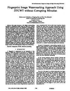
Figure 8 shows the minutiae extracted using cross number method and reduction in number of minutiae after applying post-processing technique. First row contains original fingerprint images. Second row shows the minutiae extracted using CN method while third row shows the reduction in minutiae after applying the proposed windowing technique. Figure 8
First row: original images, second row: minutiae extracted using CN method and third row: post-processed filtered minutiae (see online version for colours)
Fingerprint image: pre- and post-processing
5
79
Conclusions
Fingerprint post-processing increases the performance of AFIS by eliminating the false minutiae and validating the remaining minutiae. Only true and valid minutiae are helpful in fingerprint recognition. In this paper, a windowing post-processing technique for false minutiae elimination from skeletonised fingerprint image is proposed. The problem of minutiae extraction from skeletonised images has been derived from the fact that there are thousands of apparent minutiae, while actual are less than hundred. Fingerprint images are enhanced using pre-processing and minutiae are extracted from them. Pre-processing method greatly improves the quality of thinned image and eliminates a number of irrelevant minutiae which is justified with experimental results. Proposed post-processing technique successfully eliminated the false minutiae structures like spurs, bridges, ladders, ridge breaks, short ridges and holes/islands. The statistical analysis of the results obtained by the proposed approach shows the effective reduction of false minutiae. A very useful effect of the proposed minutiae extraction algorithm is that it performs correctly in dirty areas and dry images. The results are confirmed by visual inspection of images extracted from the FVC2004 fingerprint image database.
References Adler, S.L. (1998) ‘General theory of image normalisation’, Journal of Computer Vision and Pattern Recognition. Akram, M.U., Tariq, A., Jabeen, S. and Khan, S.A. (2008) ‘Fingerprint image segmentation based on boundary values’, 3rd International Conference on Computer Vision Theory and Applications (VISAPP08), Portugal. Andrew Sr., W., Bolle, R.M., Ratha, N. and Pankanti S. (2002) ‘Fingerprint minutiae: a constructive definition’, IEEE ECCV Workshop on Biometrics. Chen, Z. and Kuo, C.H. (1992) ‘A topology-based matching algorithm for fingerprint authentication’, Proc. of 25 Annual IEEE International Carnahan Conference on Security Technology, pp.84–87. Cychosz, J.M. (1994) ‘Efficient binary image thinning using neighbourhood maps’, Graphics Gems IV, pp.465–473. Daugman, J.G. (1985) ‘Uncertainty relation for resolution in space, spatial-frequency, and orientation optimised by two-dimensional visual cortical filters’, Journal of the Optical Society of America, Vol. 2, pp.1160–1169. Farina, A., Vajna, Z.M.K., and Leone, A. (1999) ‘Fingerprint minutiae extraction from skeletonised binary images’, Pattern Recognition, Vol. 32, No. 5, pp.877–889. Federal Bureau of Investigation (1984) The Science of Fingerprints: Classification and Uses, US Government Printing Office, Washington DC. Fitz, A.P. and Green, R.J. (1996) ‘Fingerprint classification using a hexagonal fast Fourier transform’, Pattern Recognition, Vol. 29, No. 10, pp.1587–1597. FVC2004 (2004) ‘Fingerprint Verification Contest’, available online at (http://bias.csr.unibo.it/fvc2004.html). Gonzalez, R.C. and Woods, R.E. (1992) Digital Image Processing, Prentice Hall, ISBN 0201180758. Hong, L. and Jain A.K. (1997) ‘Fingerprint image enhancement: algorithm and performance evaluation’, Technical Report.
80
M.U. Akram, A. Tariq, S.A. Khan and S. Nasir
Hong, L., Wan, Y. and Jain A.K. (1998) ‘Fingerprint image enhancement: algorithm and performance evaluation’, IEEE Transactions on Pattern Analysis and Machine Intelligence Archive, Vol. 20, No. 8, pp.777–789. Jain, A.K. (1989) Fundamentals of digital image processing, Prentice Hall, Chapter 9. Jain, A.K. and Farrokhnia F. (1991) ‘Unsupervised texture segmentation using Gabor filters’, Pattern Recognition, Vol. 24, No. 12, pp.1167–1186. Jain, A.K., Lin, H. and Boole, R. (1997) ‘Online fingerprint verification’, IEEE Transactions Pattern Analysis and Machine Intelligence, Vol. 19, No. 4, pp.302–314. Kass, M. and Witkin A. (1987) ‘Analysing oriented patterns’, Computer Vision, Graphics, and Image Processing, Vol. 37, No. 4, pp.362–385. Kovascs-Vajna, Z.M., Frazzoni, M. and Rovatti R. (1997) ‘Fingerprint ridge distance computation methodologies’, Pattern Recognition, Vol. 33, No.1, pp.69–80. Lim, S.J. (1990) Two-dimensional Signal and Image Processing, Prentice Hall, Englewood Cliffs, NJ, pp.469–476. Liu, L. and Dai, T-S. (2006) ‘Ridge orientation estimation and verification algorithm’, Journal of Universal Computer Science, Vol. 12, No. 10, pp.1426–1438. Maio, D. and Maltoni, D. (1997) ‘Direct gray-scale minutiae detection in fingerprints’, IEEE Transactions on Pattern Analysis Machine Intelligence, Vol. 19, No. 1, pp.27–39. Malleswara, T.C. (1976) ‘Feature extraction for fingerprint classification’, Pattern Recognition, No. 3, pp.173–179. Maltoni, D., Maio, D., Jain, A.K. and Prabhakar S. (2003) Handbook of Fingerprint Recognition, Springer-Verlag. Neusius, C. and Olszewski J. (1994) ‘A noniterative thinning algorithm’, ACM Transactions on Mathematical Software, Vol. 20, No. 1, pp.5–20. Osterburg, J.W., Parthasarathy, T., Raghavan, T.E.S., and Sclove S.L. (1977) ‘Development of a mathematical formula for the calculation of fingerprint probabilities based on individual characteristics’, Journal of American Statistical Association, Vol. 72, No. 360, pp.772–778. Paul, A.M. and Lourde, R.M. (2006) ‘A study on image enhancement techniques for fingerprint identification’, IEEE International Conference on Video and Signal Based Surveillance (AVSS ‘06). Qun, R., Jie, T. and Xiaopeng Z. (2002) Automatic Segmentation of Fingerprint Images, Chinese Academy of Sciences. Rao, A. (1990) A Taxonomy for Texture Description and Identification, Springer-Verlag, New York, NY. Ratha, N.K., Chen, S. and Jain, A.K. (1995) ‘Adaptive flow orientation-based feature extraction in fingerprint images’, Pattern Recognition, Vol. 28, pp.1657–1672. Stosz, J.D. and Alyea L.A. (1995) ‘Automated system for fingerprint authentication using pores and ridge structure’, Proc. SPIE 2277. Tabbone, S. and Wendling, L. (2003) ‘Multi-scale binarisation of images’, Pattern Recognition Letters, Vol. 24, No. 3, pp.403–411. Trier, O.D. and Taxt, T. (1995) ‘Evaluation of binarisation methods for document images’, IEEE Transactions on Pattern Analysis and Machine Intelligence, Vol. 17, No. 3, pp.312–315. Yang, J., Liu, L. and Fan Y. (2003) ‘A modified Gabor filter design method for fingerprint image enhancement’, Pattern Recognition Letter, Vol. 24, No. 12, pp.1805–1817. Yanowitz, S.D. and Bruckstein A.M. (1989) ‘A new method for image segmentation’, Computer Vision, Graphics and Image Processing, Vol. 46, No. 1, pp.82–95.