First order filter attenuation and frequency parameter calculation ...
Recommend Documents
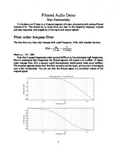
The first filter is a first order lowpass with cutoff frequency 1kHz, with transfer ...
order lowpass filter, with a sharper cutoff characteristic, would sound much more
...
measured from the splitting of peaks in an XRD rocking curve (Wruck et al., 1994). For a W' wall this angle is expected to be zero, since the W' twin law requires ...
earthquakes in CPTI04 catalogue (Gruppo di lavoro CPTI 2004) from 1100 with ... (FV), managed by OGS (the Istituto Nazionale di Oceanografia e di Geofisica ...
Mar 21, 2013 - on p-wave superconductors and extend the quasi-classical theory to include the odd-frequency dependence in the order parameter. Both of the ...
Jul 28, 2008 - satisfying the predictions of these CPS as well as investi- gations into the ..... 2 ) exhibits a mod- est peak before the first order phase transition point (Ï = â .... region of the IBA, intersecting it almost exactly for NB. = 25
Metabolically and Isotopically Non-Stationary Biochemical. Network Model. â .... The JADE concept includes a software infrastructure for sensitiv- ity analysis of ...
Apr 20, 2017 - A FibroScan measurement is also less likely to be influenced by ... The final CAP value as the median of the individual CAP values and was ...
Introduction. This issue paper explains when and how to apply first-order attenuation rate constant calculations in monitored natural attenuation (MNA) studies.
(MNA) at Superfund, RCRA, and UST sites (U.S. EPA, 1999) includes several .... Half-Lives. Both first-order rate constants and attenuation half-lives represent.
patic steatosis, the CAP score was significantly correlated with US (Ï=0.580, p90% for each ..... ation of steatosis using Fibroscan. Clin Res Hepatol ...
Nov 26, 2016 - data generated from a fully featured model of hard disk drive (HDD) ... correlations and the failure of the FORC methodology to determine the ...
degree in physics from St. Mary's College,. Winona, MN, and the M.S. degree in physics and the Ph.D. degree in radiological sciences from the University of ...
May 7, 2018 - email: tim,gert¡ @bach.ece.jhu.edu. Paper category: 2.1 Nonlinear circuits and systems. Abstractâ Log-domain filters have recently come into ...
familiar form can be implemented by a 4-transistor translin- ear loop circuit, two transistors of which are already in one of the first-order sections. One possible ...
Aug 17, 2001 - Aspects on the behavior of a general second order iterative learning control (ILC) algorithm are presented from a frequency domain perspec-.
May 8, 2013 - Bharath Ramsundar [email protected]. Computer Science Department, Stanford University. Stuart Russellâ [email protected].
[17] A. Maity, B. Chottopadhyay, U. Banerjee, A. Deyasi, Journal of Electron Devices [France], vol. 17, pp. 1400-1405, 2013. [18] A. Maity, A. Deyasi, U.Banerjee ...
Mar 25, 2012 - Zhi Li1,3, Robert Laskowski2, Toshiaki Iitaka3, and Takami Tohyama1. 1Yukawa Institute for .... pendent total energy E(q) per unit cell by VASP code.15 ..... 3 J. B. MacChesney, R. C. Sherwood, and J. F. Potter, J. Chem. Phys.
for a bulk Lennard-Jones fluid system that consists of 256 argon particles. The reliability of the ..... stands for that obtained by the MUCAMC production run above.
Production and hosting by Elsevier B.V. All rights reserved. Keywords: Frequency domain; Impact shock; Running footfall patterns; .... A least-squares best fit.
Sep 11, 2016 - Department of Mathematics, Bishop Heber College, Tiruchirappalli, TamilNadu, ..... Boundary Layers, Applied Mathematics & Mathematical.
Indian Journal of Pure & Applied Physics. Vol. 46, September 2008, pp. 667-670.
Log-domain low pass high pass first-order filter. N A Shah 1, S Z Iqbal 2 ...
Oct 30, 2013 - Out of these, the filters presented in [11, 20, 21] do not exhibit a low output ... The single active element all-pass filter presented in this.
First order filter attenuation and frequency parameter calculation ...
http://www.signalpro.biz. Approximations and filter calculations based on first
order filters. 1.0 The statement of the problem: (A common problem in ac circuit.
Approximations and filter calculations based on first order filters 1.0
The statement of the problem: (A common problem in ac circuit design)
I wish to find what the -3 dB frequency of a filter should be to attenuate a signal by 80 dB at some high frequency fh. The -3dB frequency can be called fl. Generically the two frequencies would be called fl and fh. I want use a first order filter whose attenuation is 6 dB/octave. The figure below illustrates the issue graphically. -3 dB
Attenu ation -80 dB
fl
fh
f
How can the solution of this problem be reduced to a technique that allows easy calculations? To do this, note that a first order filter will attenuate by 6 dB per octave of frequency change. Then lets multiply fl by 2N which will express the octaves of frequency above fl using fl as the starting point. For example if: fl =2khz, then 4 octaves above this will be: f(4 octaves) = 2 * 16 = 32 kHz. _________________________________________________________________ Signal Processing Group Inc., technical memorandum, September 2010, Website: http://www.signalpro.biz
And so on. Lets take the lower frequency and muliply by 2N and equate it to the higher frequency, or: fl* 2N = fh
(1)
then, 2N = fh/fl
(2)
N is the number of octaves between fl and fh. Using the following logarithmic identity we can find N. N = log10 (fh/fl)/0.30102
(3)
0.30102 = log102 The above logarithmic formula is simply a change of base from 10 to 2. Once we know how many octaves, we know the attenutation for a first order filter. The same solution should also apply to higher order filters. For example a second order filter will have an atenuation of 12 dB per octave and so on. Another example: I want the attenuation at 100 Mhz to be 80 dB. Where should the 3 dB point be using a first order filter. Solution: How many 6 dB’s are there in 80 dB? N = 80/6 = 13.3
(4) (5)
Then, _________________________________________________________________ Signal Processing Group Inc., technical memorandum, September 2010, Website: http://www.signalpro.biz
fl = fh/2N
(6)
This gives fl = 10.08E3 Hz. Then our filter should have : ( if it is a RC filter) RC = 1/10.08e3*6.28
(7)
RC = 15.79 microseconds.
(8)
Cross check: 1/(6.28*15.79e-6) = 10.08 khz. ( approx). This provids the basic design parameters for the filter. At 100 Mhz we will have a attenuation of: 13.3*6 = 80 dB
(9)
These types of problems as well as other related problems may be solved with this simple algorithm. The figure below shows the simulation results using PSPICE of the filter designed above. The components used were :
R = 10k C = 1.6 nF
_________________________________________________________________ Signal Processing Group Inc., technical memorandum, September 2010, Website: http://www.signalpro.biz
.
_________________________________________________________________ Signal Processing Group Inc., technical memorandum, September 2010, Website: http://www.signalpro.biz