2002 IEEE International Frequency Control Symposium and PDA Exhibition
FLICKER NOISE CONVERSION IN CRYSTAL OSCILLATOR Yu. S. Shmaliy, A. V. Marienko’, 0. Ibarra-Manzano, R. Rojas-Laguna Guanajuato University, FIMEE,Salamanca, 36730, Mexico,
[email protected] “Sichron“ Center, 4 Skrypnyka Str., Kharkiv, 3 10057, Ukraine
’
- A single port llf model is examined of a crystal oscillator combined with a resonator and an equivalent negative resistance of amplifier. Intrinsic l/f flicker fluctuations of resonator and amplifier amplitude and phase are converted to the oscillator amplitude and phase, and the proper transformation coefficients are applied. An analysis of the oscillator phase power spectral density is provided in detail for the particular case of a resonator excited in oscillator at various frequencies. Conformity with the Leeson’s model is shown.’ Keywords - Flicker noise, spectral density, crystal oscillator, noise model
Abstract
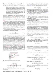
Janushevsky. In each case the model fitted data more than well. Just to illustrate, we bring the Fig. 1, where the non trivial Curtis shape [ 5 ] was simulated almost precisely, except for the random frequency walk range below 100Hz.
1. INTRODUCTION Amplitude and phase power spectral densities of a crystal oscillator are shaped by flicker fluctuations and additive thermal noises of both an amplifier and resonator. Leeson was the first who offered in 1966 [ l ] a physical but rather heuristic explanation of the forming mechanism. Then plenty of papers were devoted to the problem being aimed to predict the phase power spectral density shape with to say an engineering accuracy. Such efforts were done with respect to an open and closed oscillator loop either. An overwhelming majority of papers considers crystal resonator as just a source of l/f noise with its different appearance within and beyond a bandwidth. Such an approach did not lead yet to appreciable results that is explained by the only reason: A resonator itself “hides” several intrinsic l/f noise sources inside, which assemblage forms its amplitude and phase power spectral densities. First, we meet this hypothesis in the early work of Kuleshov and Janushevsky [2], the results then were accumulated in [3]. What is the essence? They just assumed the resonator motional inductance L, , capacity C,, resistance R,, and even static capacity C,,to be flicker noisy, have measured their flicker coefficients, and then analyzed their effect in the amplitude and phase either. If to recall that flicker noise has recently been reveled almost in each electronics unit [4] then such a hypothesis seems realistic. Employing this idea, we have analyzed in [SI a basic l/f noise model of crystal resonator, provided the proper transformation coefficients for each l/f source to the amplitude and phase, and examined the model for several experimental data published for over two decades by Wainright et al., Driscoll, Curtis, and
100
102
r, nz
IO’
10’
IDS
Fig. 1. Measured (points, 161) and simulated [ 5 ] phase power spectral density of the crystal resonator, 125 MHz
In this report, we follow the tradition considering a generalized one port oscillator model with a flicker noisy resonator and amplifier. We first convert l/f intrinsic flicker fluctuations of a resonator and an amplifier to the oscillator amplitude and phase. Then we make analysis of the oscillator possible phase noise spectral densities employing the resonator (Fig. 1) and a feedback amplifier with given amplitude and phase noises. Finally, we show that, like the resonator case [ 5 ] , the oscillator phase spectral density may be efficiently predicted depending on weights of the particular noises. Conformity with the Leeson’s model is noted.
‘
This work was partially supported by CONACYT under the project No. 535313-A
0-7803-7082-1/02/$10.00 0 2002 IEEE
101
665
11. ONE PORT NOISY MODELOF CRYSTAL OSCILLATOR
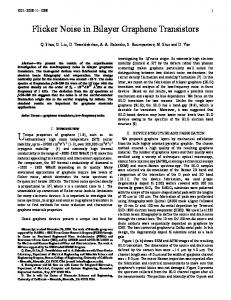
Figure 2 shows a single-port model of crystal oscillator.
1 1 -=-+-
Fig. 2. One port model of a crystal oscillator
Here
4=
(7)
8.13 4 ’
is a complex impedance of a resonator
Zqe-jqq
is with its noisy module Z, and phase P(, and 4 = ZAe-JqA that of an amplifier with its noisy module ZA and phase (PA.
1
which with account of (4)--(6)
transfers to
A , Oscillation Conditions
Transfer
function of a resonator branch is K, (jo) = u I i = zq , and that of an amplifier feedback in turn
is K , (jo) = -i I u = - 1I z, . Instantly the steady state balance relation appears in a form of K,(jo)K,(jw) =1 being satisfied by an equality
where an additional resistance is
+ 2ZqZAcos(cp,
z,z
- cp,) ,
(9)
and a phase w1 is written as
y~= , -arctgwhich produces the balance equations for the amplitude and phase, these are, respectively
x+Ax
,
L+AY where the additional variables are readily expressed as
2, = -2, cp -