techniques used for ad-hoc network routing protocols. Al- ... can be classified in two categories according to the service .... checking of Ad-hoc network protocols.
IEEE MELECON 2004, May 12-15, 2004, Dubrovnik, Croatia
Formal Verification of Ad-Hoc Routing Protocols Using SPIN Model Checker R. de Renesse, A.H. Aghvami Center for Telecommunication Research, King’s College London, UK {ronan.de renesse, hamid.aghvami}@kcl.ac.uk
Abstract— Tests and simulations are the only verification techniques used for ad-hoc network routing protocols. Although these techniques give us an excellent overview of the protocol behavior, some undesirable aspects of the protocol could still be undiscovered. Therefore formal verification is needed. This paper presents a new technique to formally verify such protocols by the use of a well-known modelchecker: SPIN. As an example, a formal verification of the Wireless Adaptive Routing Protocol(W.A.R.P) has been performed.
I. I NTRODUCTION An ad-hoc network is an infrastructureless network consisting of mobile terminals with the capability to communicate with each other. Every mobile node acts as a router and forwards traffic originated by other nodes. Each node is able to dynamically discover and maintain routes to other nodes in the network. Established routes should be loop-free and route changes should converge quickly even in large networks. Ad-hoc routing protocols can be classified in two categories according to the service policy they follow: table-driven protocols and on-demand protocols [1]. Table-driven routing protocols maintain up-to-date routes between all nodes in the network. This requires each node to maintain some kind of routing table to store routing information. The ability of the protocol to provide routes to mobile nodes depends on the consistency of routing tables. Therefore, a node noticing a change in network topology must propagate the updated routing information to the other nodes. In the on-demand routing protocol case, routing information is acquired only when it’s needed. No fully consistent routing tables are maintained; hence whenever a node wants to communicate with another node, it initiates a specific route discovery process to obtain a valid route. On average, on-demand protocols have been found to perform better than table-driven protocols, even though there are some scenarios where characteristics of a tabledriven solution outperform the on-demand approaches [1], [2]. Validation techniques used for ad-hoc network protocols are simulation and testing. This is an operational way to check whether a given system realization conforms to an abstract specification. By nature, testing can be applied only after a prototype implementation of the system has been realized. Formal verification, as opposed to testing, works on models (rather than implementations)
0-7803-8271-4/04/$20.00 ©2004 IEEE
and amounts to a mathematical proof of the correctness of a system. Both techniques can be supported by tools. SPIN model-checker is one of these tools which can perform simulation and verification. II. F ORMAL VERIFICATION A. Overview A complementary technique to simulation and testing is to prove that a system operates correctly. The term for this mathematical demonstration of the correctness of a system is formal verification [3], [4]. In model checking[5], algorithms executed by computer tools are used in order to verify the correctness of systems. The user gives a description of the system (the possible behavior) and defines the requirements (the desirable behavior). Knowing these parameters, the machine can perform a verification of the model. If an error is found, the tool provides a counterexample showing under which circumstances the error can occur. This allows the user to locate the error and then repair the model specification. If no errors are found, the user can refine its model description and can restart the verification process until the model specifications converge to the real system. B. SPIN model checker SPIN is a generic verification system [6] that supports the design and verification of asynchronous process systems. This model checker accepts design specifications written in the verification language PROMELA (a Process Meta Language) [7], and it accepts correctness claims specified in the syntax of standard Linear Temporal Logic (LTL) [8]. The validators that are produced by SPIN are among the fastest programs for exhaustive searching known to date [7]. The validators can be used in two different modes. For small to medium size models the validators can be used with an exhaustive state space. The result of all validations performed in this mode is equivalent to an exhaustive proof of correctness, for the correctness requirements that were specified. For systems that are larger, the validators can also be used in supertrace mode, with the bit state space technique [9]. In these cases the validations can be performed in much smaller amounts of memory, and still retain excellent coverage of the state space.
1177
Because of mobility, ad-hoc network analysis is highly complex from the validators point of view. Therefore, the supertrace mode is more suitable for such systems. SPIN uses a hash-factor[9] to serve as a predictor coverage function, which is defined as: M N0 N’ equals to the number of states reached and M equals to the maximum number of storable states. The corresponding coverage is:
fi Each time we enter in this condition section timer is randomly set to 0 or 1, then, depending on timer value the appropriate action is performed. If timers like this are included in the model, it should be done for each entry of each node routing table.
Hf =
Hf > 100 =⇒ C > 99.9% 10 < Hf < 100 =⇒ 98% < C < 99.9% The results of all validations performed in supertrace mode are superior to any other type of validation performed within the same physical constraints of the host machine (e.g., memory size and speed)[9]. III. A D - HOC NETWORK IMPLEMENTATION UNDER SPIN SPIN is a model checker made for fixed communication protocols by the use of the PROMELA language. Therefore, some add-ins must be implemented under PROMELA to adapt SPIN to the modelling and the checking of Ad-hoc network protocols. A. The broadcast system Promela language is based on point to point communication. Thus, when two nodes want to communicate they use one predetermined channel ,chan broadcastX, which makes the connection between them. To model the broadcast system, there must be as many channels as nodes. Each of these channels is associated with a different node and each node can receive messages only through this channel chan broadcastX. Then, depending on node’s neighbourhood, each node finds and uses the corresponding channel to send messages of all kinds. Here is an example: if :: (routing-tab1[k].next-id == 2) → broadcast2!lu,source-id,destination-id :: (routing-tab1[k].next-id == 3) → broadcast3!lu,source-id,destination-id :: (routing-tab1[k].next-id == 4) → broadcast4!lu,source-id,destination-id fi; B. Timers Promela doesn’t provide any time features except a timeout function described in [10]. The timeout keyword is a modelling feature that provides an escape from a hang state which doesn’t correspond to the real timer definition. Timers are just triggers from the verification process point of view. A timer could be modelled as follows: if :: timer=1 → goto cancel-entry :: timer=0 → skip
C. Mobility An ad-hoc network node doesn’t distinguish between its movements and its neighbors movements. All a node will see is a broken link. Modelling node mobility with the Promela language consist of cancelling all routing table entries of the moving node, and setting a new link initialisation for this node. Thus, the node looses contact with its former neighbors and makes contact with new ones. All nodes which were connected to the moving one must also have their corresponding routing table entries removed. Notice that ad-hoc network nodes mobility is modelled under Promela without the use of timers. There is also another way to check the protocol behaviors over mobility by the use of the case selection[10] in the initialisation phase of the model. The case selection feature provided by Promela allows us to randomly choose between statements. In the intialisation case, statements correspond to link setup with one specific node in the network: if :: neigh-id=2 → broadcast2!1,my-id,destination-id :: neigh-id=3 → broadcast3!1,my-id,destination-id :: neigh-id=4 → broadcast4!1,my-id,destination-id fi; Therefore, each time we compute the model, a new network topology is randomly set. During the verification process, the model-checker SPIN checks all possibilities of the case selection. Thus, all possible network configurations are checked in every possible order knowing that each node randomly initialise contact one after the other. This kind of mobility modelling is less complex than the first presented in this subsection from a “modelchecking” point of view. IV. WARP - W IRELESS A DAPTIVE ROUTING P ROTOCOL Ad-hoc routing protocols can be classified in two categories according to the service policy the protocol follows: table-driven protocols and on-demand protocols(See section I). The Wireless Ad-hoc Routing Protocol (WARP)[11] belongs to both categories. It attempts to maintain up-todate routes between all nodes in the network with routing tables and link-update propagations. If there is still no valid routes for a specific destination, it uses a route discovery process. A. Routing table structure Each node has a routing table with four different columns:
1178
Destination: The destination field is the IP address of the destination node. Hop: The hop field indicates which is the next hop on the route towards the destination. Backup: The backup field contains another next hop on the route towards the destination in case the route proposed by the hop field is not available. The backup field is used only if the corresponding destination is not an adjacent node. Timer: The timer field is only present for adjacent nodes, i.e. nodes that are within wireless transmission range.
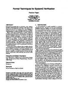
HELLO message: The LU source would be the node address and the LU destination would be the destination entry corresponding to the next hop entry modified. There is no intermediates nodes in this case. See figure 1, table I, and table II. valid LU: it would be the same excepted that the source of the LU received would be added into the LU intermediates nodes. See figure 2, table III, and table IV. LU(1,-,2)
4
LU(1,-,2)
1 3
LU(1,-,2)
B. Hello messages As in AODV, WARP uses hello messages to maintain contact with its neighbors and also to contact new neighbors. Hello messages indicate the presence of a node. A hello message received informs nodes of the neighborhood topology. Depending on where the hello message is coming from, a node interprets it differently. If it is known as a non adjacent node, the next hop field of the corresponding entry in the routing table is set to the sender id number and the timer is restarted. If the sender of the hello message is totally unknown, then a new entry is created in the routing table. Hello messages are frequently sent by each node. If frequently hello messages are not received from a neighbor, the timer of the corresponding entry expires, and is cancelled. An hello message is supposed to have only one piece of information: hello message source id number, which identifies the node from where the hello message is coming from.
2
Fig. 1.
LU after HELLO received
TABLE I ROUTING TABLE - N ODE 3 Destination
Next Hop
Backup
Timer
1
1
-
count. down
4
4
-
count. down
2
1
-
started
TABLE II ROUTING TABLE - N ODE 4 Destination
Next Hop
Backup
Timer
1
1
-
count. down
3
3
-
count. down
2
1
-
started
C. Link Updates - LUs Link updates bring information about the network topology beyond adjacent nodes. LUs are broadcasted whenever there is movement in the network. A LU provides a node identity number and the route to reach it. With this information, a node determines whether to broadcast the LU or not. Here is the format of a link update:
LU(4,1,2)
4 LU(4,1,2)
LU(3,1,2)
3
Fig. 2.
1
2
LU(3,1,2)
LU after LU received
LU (Source, Intermediates N odes, Destination) Source is the address of the LU sender, Destination is the route destination to update and Intermediates Nodes corresponds to the route used by the link update so far. Because a link update travels through the network, it represents the most up to date network topology information. Therefore, any addresses and routes stored in the LU will be inspected for useful information, which will be added to the routing table. If a received LU contains the current node address, it will be discarded after using information brought by it. Figure 1 is a simple example of LU propagation. Whenever a node notices a valid modification in the next hop field in the routing table, it broadcasts a LU. There is a valid modification when the next hop information changes to a valid entry. A LU can be sent after receiving:
1179
TABLE III ROUTING TABLE - N ODE 3 Destination
Next Hop
Backup
Timer
1
1
-
count. down
4
4
-
count. down
2
1
4
count. down
TABLE IV ROUTING TABLE - N ODE 4 Destination
Next Hop
Backup
Timer
1
1
-
count. down
3
3
-
count. down
2
1
3
count. down
D. Reporting route failures When a link break occurs, a WARP node does not inform its neighbors. It just cancels every entry in its routing table corresponding to the missing adjacent node. If another node wants to use the cancelled route, it sends back an ICMP message to this node. Thus, the node is aware of the route failure and chooses another path to the destination using the backup field in their routing table or using reactive routing. E. Reactive routing Link breaks, timer expiration and ICMP messages can make a destination unreachable. To escape this deadlock state, WARP nodes use Reactive Routing. Reactive Routing is defined by the use of Route Request (RREQ) and Route Reply (RREP) messages to find a destination. AODV also uses reactive routing [12]. Contrary to AODV, WARP doesn’t use Broadcast-ids and sequence numbers to avoid loops, each node has a route request cache instead. Each node uses information provided by this message to update its routing table but there won’t be any LU propagation due to this modifications. This is done to prevent large waves of update messages. V. WARP VERIFICATION (a) Basic model
A. Complexity reduction Because the verification is bounded by the amount of physical memory available on the computer, we need to reduce the system complexity. Complexity reduction is the most important part of the verification. Due to mobility, the state space increases exponentially with the complexity of the protocol model. Therefore, we modelled a five node ad-hoc network. Five nodes represents enough different network configurations that a verification done on it provides a great probability of good behavior for larger networks. No-one has proved the correctness of an ad-hoc network routing protocol over more than five nodes so far [13], [14], [15]. We verify properties of WARP protocol and not performance. Two models have been made: The full model containing all properties of the WARP protocol and the Basic model which is a simplification of the full model optimized for verification. the basic model has been simplified by reducing the code and the number of properties included in the model until a good verification result was obtained. Parse trees of both models are shown on figure 3. These figures make us notice the complexity involved by the implementation of timers, movement, and data communication. The number of states has been divided by five. B. Modifications Reduction of state space and Promela language complexity involve divergences between our model and the original WARP protocol. Here are the rules managing the basic model: • There are five nodes in the model(a sender, a receiver and three intermediates).
Fig. 3.
(b) Full model Models’s parse tree
Each node can initialise only one link with another node(this is made to avoid state space explosion). • Node 1 sends only one data message to node 5 after the link updates are propagated. • Node 1 must’nt be in direct connection with node 5(checking direct communication between node 1 and node 5 is obviously not useful). • Nodes all arrive in the network one after another(thus, all sequential patterns - order of arrival are checked) • The model arrives in idle state whenever the data packet is received by node 5 or the destination declared unreachable by node 1(therefore, if there are loops the model will run for ever and SPIN will declare an error). These rules describe the environment of the WARP protocol basic model we want to verify. This model is made to check link update propagations and message delivering in every five-node network respecting these rules. The reactive part of the protocol and route failure reporting are properties of WARP which are not included in the model since they are add-in features made to improve performances. These properties can be verified independently using a different model. •
C. Simulations The XSPIN graphic interface is used in order to make simulations. An important number of simulations has been made before finding a model which suits the requirements.
1180
A simulation of the basic WARP Model is described on figure 4. node_2:2 8 node_1:1 9 node_3:3 19 node_5:5 55
1!1,2,2,0,0,0 3!1,3,3,0,0,0 2!1,1,1,0,0,0 100 131 317 331 344
3!1,3,3,0,0,0 250 2!1,1,1,0,0,0 6!1,3,2,0,0,0 385 2!1,1,3,0,0,0 3!1,3,2,0,0,0
node_4:4 66 160 173
358 372
204 1!1,5,5,0,0,0 225
link updates propagation. The last two arrows represent a data transfer from node 1 to node 5(passing by node 3). The corresponding network topology is shown on figure 5. figure 6 is the execution bar panel corresponding to the simulation run shown in figure 4. It shows the percentage of all system steps executed per process. This can be representative of real-time activity in the network for each node. Work overload and congestion problems could be noticed and solved using this tool.
183
Percentage of 1763 System Steps 1!1,4,4,0,0,0
427
394 408 420
Executed Per Process (5 total)
570
6!1,3,5,0,0,0 3!1,4,1,0,0,0 659 3!1,3,5,0,0,0 1!1,2,2,0,0,0 706 720 788 867
577 619 633 1!1,5,5,0,0,0 6471!1,4,4,0,0,0 5!1,3,5,0,0,0 661 666
2!1,1,2,3,0,0 1!1,1,3,0,0,0
829
845
6!1,3,4,0,0,0 3!1,3,4,0,0,0 936 1!1,1,2,3,0,0 1120 1134 1165
876 890 904 918 934
1!1,4,1,0,0,0 5!1,3,4,0,0,0 930
1069 2!1,3,4,0,0,0
1!1,2,5,3,0,0 13442!1,1,5,3,0,0 3!1,4,2,1,3,0
1376
1!1,1,5,3,0,0 1!1,2,4,3,0,0 3!1,4,5,1,3,0
1578
1489 1526
99
1
2
3
4
5
node_2
node_3
node_4
node_5
Fig. 6.
Execution bar panel example
1547
D. Verification 5!0,1,5,1,3,0 4!1 1763
The model is very large(more than 100 million states), therefore the supertrace/bitstate mode is more appropriate to the model verification. We check for invalid end states which occur when a dead-lock state is found in the model, or when the maximum depth search is reached during the verification (which means that processes don’t stop = loops in the model). With a Pentium 4, 1GB of RAM, the maximum number of states that the bit state space can accommodate is equal to 231 states or about 2.15 × 10⁹ states. During a verification run, SPIN checks all possible fivenode network configurations assuming the rules explained in V-B. Table V shows link possibilities for each node in the basic model. It is therefore easy to calculate the number
1750 1752 1758
1763 1768
Simulation of the basic WARP model
2
5 3
1
395
1!1,5,4,3,0,0
1763
Fig. 4.
614
1252
1635 1639 1643 1647 1651 1709 1743
1!0,1,5,1,3,0
185
node_1 1394 1417 1480
1419
1702
464
4
TABLE V Fig. 5.
Corresponding network topology
LINK POSSIBILITIES FOR EACH NODE
Each line represents each process: node 1 , node 2, etc. Each box represents one step in the communication process, which means each time a process receives or sends a message a new box appears on the process line. The number in the box corresponds to the simulation step. Arrows correspond to the message transfer, and numbers on these arrows correspond to transmitted message value. Also, “!” means sending and “?” means receiving as described in [10]. The first arrows set the initial configuration of the network and the following arrows represent the
Node 1
Node 2
Node 3
node 4
node 5
2 3 4 -
1 3 4 5
1 2 4 5
1 2 3 5
2 3 4 -
N l1 = 3
N l2 = 4
N l3 = 4
N l4 = 4
N l5 = 3
of different possible network topologies:
1181
C = N l1 × N l2 × N l3 × N l4 × N l5
(1)
TABLE VI 16 VERIFICATIONS
where C is the number of network configurations and N li the number of different possible links for the node i. Thus: C = 3 × 4 × 4 × 4 × 3 = 576 possibilities If we generalize for N nodes following the rules explained before, we obtain: ( N − 2 ∀i ∈ {1; N } (2) N li = N − 1 ∀i ∈ {2; . . . ; N − 1} C=
N Y
N li
(3)
i=1
After some simplifications 3 becomes: µ ¶2 N −2 C= (N − 1)N N −1
(4)
Setting N = 5, C = 576. The same result as before is obtained. Notice that for N = 4, C = 36; for N = 6, C = 10000. This is an example of state space explosion involved when the number of nodes present in the network increases. SPIN can’t check the 576 possibilities in one verification run. So, the number of possibilities, C, generated by the model must be reduced. To do so we imposed N l3 = 1 and N l4 = 1. The corresponding number of network topologies checked is: C = 3 × 4 × 1 × 1 × 3 = 36 possibilities SPIN does this verification in less than 30 minutes and perform an average coverage of 98%(hash factor over 10). In order to check the other 540 network configurations, we need to perform another 15 verifications like the one above(15 × 36 = 540 possibilities). Each of the 16 verifications that should be performed must cover a different set of possibilities. To do so, we perform 16 verifications on the model, changing each time the id of the neighbor(N eighidi )in node 3 and node 4. Here are the values: N eighid3 ∈ {1, 2, 4, 5} N eighid4 ∈ {1, 2, 3, 5} The number of permutations between these two groups of numbers equals to 16. Table VI presents the results for these 16 verification runs. VI. C ONCLUSION & F UTURE W ORKS We have shown that ad-hoc network routing protocols properties can be formally verified using SPIN modelchecker by proving the correctness, at 98%, of a 5-node model of the Wireless Adaptive Routing Protocol. The number of mobile equipments users, such as mobile phones, PDAs, and laptops, is increasing tremendously and ad-hoc networking is one solution for connecting these devices. Therefore, protocol reliability becomes as important as protocol performance; formal verification is an excellent technique for gaining true reliability.
N eighid3
N eighid4
Hash Factor
Coverage
1
1
14.11
98%
1
2
18.42
98%
2
1
18.51
98%
2
2
17.47
98%
1
3
13.29
98%
4
1
15.64
98%
4
2
16.64
98%
4
3
113.14
99.9%
5
1
43.94
98%
5
2
40.96
98%
5
5
51.38
98%
5
3
25.27
98%
2
5
41.15
98%
2
3
16.38
98%
4
5
25.96
98%
1
5
44.05
98%
R EFERENCES [1] S.-J. Lee, M. Gerla, and C.-K. Toh, “A simulation study of table-driven and on-demand routing protocols for mobile ad hoc networks,” IEEE Networks, vol. 13, no. 4, pp. 48–54, 1999. [2] E. Royer and C.-K. Toh, “A review of current routing protocols for ad-hoc mobile wireless networks,” IEEE Personnal Communications, vol. 6, no. 2, pp. 46–55, 1999. [3] J. Katoen, “Concepts, algorithms and tools for model checking,” Lecture Notes 1998/1999, chapt.1: System Validation. [4] N. A. S. A. LARC, “What is formal methods?” http://shemesh.larc.nasa.gov/fm/fm-what.html, formal methods program. [5] P. Wolper, “An introduction to model checking,” 1995, position statement for pannel discussion of the Software Quality Workshop, Unpublished Note. [6] G. J. Holzmann, “The model checker spin,” IEEE Transactions on Software Engineering, vol. 23, no. 5, pp. 279–295, May 1997. [7] ——, Design and Validation of Computer Protocols. Prentice Hall, November 1990. [8] L. Lamport, “The temporal logic of actions,” ACM Transactions on Programming Languages and Systems, vol. 16, no. 3, pp. 872–923, May 1994. [Online]. Available: citeseer.ist.psu.edu/article/lamport94temporal.html [9] G. J. Holzmann, “An analysis of bitstate hashing,” Formal Methods in Systems Design, November 1998. [10] R. Gerth, “A concise language reference for promela,” http://spinroot.com/spin/Man/Quick.html. [11] P. Khengar and A. H. Aghvami, “Warp – a new hybrid routing protocol for mobile ad hoc networks,” IEEE Journal on Selected Area in Communications, to appear in 4th quarter 2004. [12] C. Perkins, E. Royer, and S. Das, Ad Hoc On Demand Distance Vector (AODV) Routing, 2003, iETF Internet Draft, draft-ietfmanet-aodv-13.txt, work in progress. [13] T. Lauschner, A. Macedo, and S. Campos, “Formal verification and analysis of a routing protocol for ad hoc networks,” July 1997, available at http://jurua.dcc.fua.br/ tanara/artigo.html. [14] K. Bhargavan, C. A. Gunter, and D. Obradovic, “Formal verification of standards for distance vector routing protocols,” Journal of the ACM, vol. 48, no. 4, pp. 538–576, 2002. [15] I. Zakiuddin, M. Goldsmith, P. Whittaker, and P. H. B. Gardiner, “A methodology for model-checking ad-hoc networks,” Lecture Notes in Computer Science, vol. 2648/2003, no. 0302-9743, pp. 181–196, January 2003.
1182