On the Formal Verification of Routing in Material Handling Systems Thomas Klotz1 , Norman Seßler1 , Bernd Straube1 , Eva Fordran1, Karsten Turek2, and Jens Sch¨onherr3
Abstract— The correct design of complex material handling systems (MHS) is a challenging task, mainly because of short development cycles and ever increasing system sizes. For baggage handling systems (BHS) at airports, the correct design of routing strategies is of special importance, as these strategies are non-trivial but safety-critical. This paper presents a novel approach to prove the correctness of routing in MHS. The approach is based on assume-guarantee reasoning which allows to derive proofs of the overall system using a divide and conquer strategy. The proposed approach is automated and has been implemented in a tool. The application of the approach is shown using a real-world BHS.
I. I NTRODUCTION The correct design of today’s material handling systems (MHS) becomes more and more difficult mainly because of their growing size and complexity. One typical example for such systems are baggage handling systems (BHS) at airports connecting a large number of gates and terminals. These systems may consist of several hundreds or even thousands of single system components. Especially the implementation of complex routing strategies is cumbersome and error-prone, as these strategies have to deal with load balancing, alternative routes in case of a failure, several levels of security checks, etc. In addition, routing can partially be implemented based on local strategies on Programmable Logic Controller level and/or based on global strategies provided by a material flow computer (MFC). By validating the logistic system using simulation, design errors can be found. However, the absence of design errors cannot be proven. Model checking [1] as a formal method, however, provides a general means to prove the correctness of the system with regard to its specification. Petri nets have been utilized for analysis of logistic systems at a high level of abstraction, e.g. for modeling supply chains and workflows, schedulability analysis, stochastic evaluation, etc. An overview on recent developments can be found in [2]. However, this work aims at the verification of the material flow control system and the conveying controls. The field of formal verification of MHS has been tackled by few works only. D¨udder et al. [3] discuss the advantages This work was partially supported by the German Research Foundation under grants STR 412/4-1 and SCHM 2689/3-1. 1 T. Klotz, N. Seßler, B. Straube, and E. Fordran are with the Fraunhofer Institute for Integrated Circuits, Zeunerstr. 38, Dresden 01069, Germany (e-mail:
[email protected]). 2 K. Turek is with the Chair of Logistics Engineering, Institute of Material Handling and Industrial Engineering, Technische Universit¨at Dresden, Dresden 01187, Germany (e-mail:
[email protected]). 3 J. Sch¨ onherr is with the Dresden University of Applied Sciences, Dresden 01069, Germany (e-mail:
[email protected]).
of applying model checking in the field of MHS and present the model of a conveyor. In [4], [5], it is shown how to model an MHS in order to apply model checking. However, the whole modeling is done manually for each system. Another related field is the verification of routing algorithms of communication networks. Renesse and Aghvami [6] show how to formally verify a five node network using the SPIN model checker. The state space explosion seems to hamper the application to larger networks. Camara et al. [7] propose an approach to the verification of mobile ad-hoc networks. Abstractions were applied to reduce the state space. However, the approaches mentioned above do not utilize model libraries in order to allow reuse. On the contrary, the authors of this paper introduced a modeling methodology for MHS that allows to apply model checking to verify these systems [8], [9]. The problem with the existing approach is scalability, i.e. it can only be applied to systems of a moderate size. Thus, in order to cope with this problem, a compositional approach for the verification of MHS has been developed. The approach is based on the theory of assume-guarantee reasoning which allows to derive properties of the overall systems from proving properties of its subsystems. Therefore, the MHS is partitioned into subsystems that are subsequently verified separately. This paper focusses especially on the verification of routing in MHS. The paper is organized as follows: The necessary preliminaries are given in Section II. The modeling methodology for MHS is revisited in Section III. A compositional approach to the verification of routing in MHS is thoroughly explained in Section IV. The application of the approach to verify the routing in the BHS of an international airport, as a real-world case study, is presented in Section V. Section VI concludes the work and provides directions for future work. II. P RELIMINARIES Model checking [1] allows to automatically prove whether a set of properties representing the specification holds on a model. Model checking systematically explores all the states of the model in order to check the required properties. If a property does not hold on the model, a counterexample in terms of a simulation trace is generated and presented to the user to ease debugging. The model is typically specified using finite state machines (FSM) [10]. Additionally, the requirements to the system have to be formalized as properties in terms of temporal logic formulas. A major problem of model checking is the so-called state space explosion problem. This refers to the fact that the number of states of a system grows exponentially with the
size of the system description. One method to tackle the state space explosion problem is compositional verification. It follows the principle of divide and conquer: properties of a complex system are derived from properties of its modules. With this, the model checking can be carried out on the single modules separately, and thus, state explosion is reduced. However, modules are usually designed in such a way that they only fulfill certain properties in a given environment (context). Based on this idea, assume-guarantee reasoning (AGR) [11] has been proposed. In AGR, tuples of the form hAi M hP i are checked by stating that if the module M is part of a system that satisfies the assumption A, then it is guaranteed that the property P holds. To prove a property P for the composition of two FSMs M1 and M2 , the basic assume-guarantee rule [12] can be used: hAi M1 hP i htruei M2 hAi htruei M1 k M2 hP i
(AGR-2)
The rule denotes that if M1 satisfies P under the assumption A, and if M2 satisfies assumption A unconditionally, then the composition of M1 and M2 satisfies P . By repeatedly applying this rule, it can be generalized to n modules [13]: hA1 i hA2 i
M1 M2 .. .
hP i hA1 i
hAn−1 i Mn−1 hAn−2 i htruei Mn hAn−1 i htruei M1 k M2 k . . . k Mn hP i
(AGR-N)
Grumberg and Long [12] proposed the temporal logic A-Computation Tree Logic (ACTL) to be appropriate for using model checking to do AGR. For ACTL, a standard model checker is sufficient to prove whether a formula is true for all systems containing a certain module. A problem of AGR is to determine appropriate assumptions. The assumptions have to be a valid abstraction of the entire system, though, if an assumption is too weak, false negatives may occur. Thus, automatically finding sufficient assumptions is a key issue in AGR. III. M ODELING
METHODOLOGY FOR
MHS
This section briefly explains the existing modeling methodology for MHS [8], [9]. The notion of MHS elements is revisited in Section III-A, and then, a description of the MHS network is proposed in Section III-B. Section III-C introduces MHS elements that allow routing. A. MHS elements The technical MHS is decomposed into a quantity of commonly used MHS components. For each of these technical MHS components, a behavioral model, the MHS element, is set up. This MHS model abstracts from the technical behavior in order to provide a discrete model. The model
INi-1 Stopi-1 Prei-1
MHS Element i-1
Takei-1
OUTi-1
INi
Errori-1
Stopi
Givei-1
Prei
MHS Element i
OUTi Errori Givei
INi+1
MHS Stopi+1 Element i+1 Prei+1
Suci-1
Takei
Suci
Takei+1
Acki-1
Cleari
Acki
Cleari+1
Cleari-1
Fig. 1.
Acki+1
OUTi+1 Errori+1 Givei+1
Suci+1
Interconnection of MHS elements
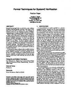
of the technical MHS is obtained by combining instances of the single MHS elements to a network of interconnected MHS elements. This model is then used for formal verification, simulation, etc. To discretize the technical MHS wrt. space and time, the following assumptions and restrictions are applied: • The length of a cargo is 1 Length Unit (LU). • At each discrete time step t, a cargo can move 0 or 1 LU. • At each place, there can be only one or no cargo. • The set C defines the types of cargos that have to be distinguished. A cargo type is specified by a letter such as a, b, c, . . . • The special cargo type L ∈ C represents “no cargo”. MHS elements are modeled using FSMs and have a defined set of input and output variables. MHS elements can be interconnected in an arbitrary order such that the resulting network itself can again be regarded as an MHS model. That means, an MHS model is a network of MHS elements and/or MHS subnetworks which, in turn, are such interconnections. Figure 1 shows a simple example of a network consisting of a series connection of three MHS elements. The subsequent MHS elements i − 1, i, and i + 1 are linked by connecting and identifying the variables OUT i−1 → IN i , Give i−1 → Pre i , OUT i → IN i+1 , Give i → Pre i+1 , Clear i → Ack i−1 , Take i → Suc i−1 , Clear i+1 → Ack i , and Take i+1 → Suc i . The variables have a given semantics [8], e.g. the variable Give may only become 1 if the MHS element wants to transfer a cargo. The variables Clear and Ack are only necessary for segmented MHS elements, where the receipt of each cargo has to be acknowledged before the next cargo can be transported. For MHS elements transporting more than one cargo at a time, these signals can be omitted. MHS elements that have been modeled are, amongst others, conveyors, turntables, pushers with routing function, cargo sources, and cargo sinks. B. MHS network This section introduces a description of MHS networks (cf. Figure 2). The following notation is used: regular uppercase letters refer to single components and calligraphic uppercase letters to sets of components, e.g. N is a set of components with the type N. Lower case italic expressions refer to data types. The symbol “|” describes an alternative, “[” and “]” mark optional components. Moreover, a function to return a subcomponent is defined by the subcomponent
:= hE , SRC, SN K, CN , Sin , Sout , Cglobal i MHS element E := hID, ET, CP in , CP out , Sin , Sout , [E P]i Source SRC := hID, CPout , Sin , Sout , Cout i Sink SNK := hID, CPin , Sin , Sout i Connection port CP := hCNin | CNout i Connection CN := hID, CPogn , CPtgt i Signal S := hID, STi Signal type ST := hsignal type enumi Element type ET := helement type enumi Element parameter EP := hint value | Ci Cargo C := hcargo type enumi Identification ID := hstring valuei MHS network
Fig. 2.
N
Description of the MHS network
name followed by round brackets, e.g. the expression ET(E) represents a function to return the element type of an MHS element E. An MHS network N is a network of MHS elements E. These elements are connected to each other with connections from CN . An MHS element may be connected to a source or sink from SRC and SN K, resp. Note that sources and sinks are also MHS elements, however, they are handled separately here. The different types of cargos occurring in the network are given as Cglobal . An MHS network has input (output) signals Sin (Sout ). The global stop function is realized by adding the global signal S = hh“Stop”i , hboolean ii to each element. ET defines the type of an MHS element and, hence, the number of input and output connection ports CP in and CP out , resp.; its parameters are given in EP. The type can, for instance, refer to a conveyor where a parameter is its length. A source has one output connection port CPout and a set of cargo types Cout it can generate, while a sink has only one input connection port CPin . Through a connection port, the single input or output variables of an MHS element, such as Give, can be accessed. A connection is a link between an origin connection port CPogn and a target connection port CPtgt , and describes the wiring of MHS elements (cf. Section III-A). Signals have an ID and a type. The element type is an enumeration value. The cargo type represents the type of a good that is transported through the MHS network. Finally, the identification provides a unique identifier. C. MHS elements with routing function Figure 3 sketches the concept of an MFC and global routing strategies in the existing modeling methodology. Thin solid lines refer to signals from MHS elements, dashed lines represent signals from the MFC to MHS elements, and thick solid lines mark connections between MHS elements. Note that only the signals needed for the illustration are depicted. At the MHS element i, incoming cargos can be routed to two different succeeding elements. The routing decision, i.e. which successor is chosen in a certain situation, can be based on the current system parameters or on the history. Moreover, the routing decision may depend on local conditions, i.e. for
MHS Element j
MHS Element k
MHS Element i+1 MHS Element i-1
MHS Element i
Routing Decision
Fig. 3.
MHS Element i+2
Routing in MHS network by Material Flow Computer (MFC)
the example in Figure 3 from MHS elements i − 1, i + 1, and i+2, or global conditions provided from the MFC. The MFC receives information from all MHS elements, and thus, it can implement complex routing strategies such as load balancing, alternative routes etc. The MFC is also modeled using FSMs. IV. C OMPOSITIONAL
VERIFICATION APPROACH
As mentioned in Section I, the MHS networks have to be partitioned into subnetworks. This is described in Section IVA. Section IV-B introduces the compositional verification approach for routing in MHS. The algorithms are given in Section IV-C, while the verification results are explained in Section IV-D. Finally, the implementation of the algorithms is briefly discussed in Section IV-E. A. Partitioning of MHS networks First, the designer partitions the original MHS network (cf. Figure 2) into subnetworks leading to the description presented in Figure 4. (Practical aspects on how the partitions should be chosen are discussed in Section V.) Note that the figure only shows the components that have been changed; the remaining components stay unaltered. In the following, the changed components are briefly explained. In an MHS network, subnetworks, sources, and sinks are connected via connections CN ; sources and sinks are viewed in such a way that they are always outside of subnetworks. An MHS subnetwork is composed of MHS elements E. Connections CN link MHS elements to other elements by their input and output connection ports CP in and CP out , resp. Connection ports of a subnetwork allow for connections with sources, sinks, and other subnetworks. In order to verify routing, information about the cargo types in the MHS network is needed. Therefore, a sink refers to the set Cspec defining the cargo types that are required to reach this sink. This set is derived from the specification of the MHS. Additionally, the set Cport characterizes the cargo types at the connection ports that are determined during verification. B. Verification method The verification goal is to prove the correctness of the routing in the given partitioned MHS network, i.e. whether the set of determined cargo types at all sinks is the same as the specified cargo types Cspec . First, it is assumed that the partitioned MHS network does not have feedback loops between MHS subnetworks. The
:= hSN , SRC, SN K, CN , Sin , Sout , Cglobal i MHS subnetwork SN := hID, E , CP in , CP out , CN , Sin , Sout i Sink SNK := hID, CPin , Sin , Sout , Cspec i Connection port CP := hhhCNin i|hCNout i|hCNin , CNout ii, Cport i MHS network
Fig. 4.
N
Description of the partitioned MHS network
handling of feedback loops is discussed at the end of this section. The method to formally verify routing works as follows: the partitioned MHS network N without feedback loops between MHS subnetworks spans an acyclic directed graph where the direction is given by the flow of the cargos, i.e. from sources SRC through subnetworks SN to sinks SN K. At each of the sources, the possible cargo types being generated Cout (SRC) are defined. Thus, from the given cargo types at the sources, without any further assumptions, the possible cargo types CP out (SN) at the output connection ports of the subnetworks directly connected to theses sources can be formally verified. This first step refers to htruei Mn hAn−1 i in AGR-N (cf. Section II). Based on the verified assumptions, i.e. the proven cargo types at the input connection ports, the possible cargo types at the output connection ports of subnetworks directly connected to the subnetworks from the first step can be verified (hAn−1 i Mn−1 hAn−2 i), and so on. Finally, whenever these steps lead to the verification of the output connection ports of subnetworks directly connected to sinks, the algorithm terminates, as the properties of interest (possible cargo types at sinks) have been proven (hA1 i M1 hP i). For MHS networks with feedback loops between MHS subnetworks a preprocessing is done. While feedback loops inside MHS subnetworks stay untouched, feedback loops connecting MHS subnetworks are resolved: The beginning of each feedback loop is replaced by a source creating the cargo types Cout and an appropriate sink consuming them. The cargo types Cout that are fed back into the MHS network are automatically computed: starting with Cout := {L}, the set Cport (CPin (SNK)) of cargos reaching the sink is determined using the verification algorithm explained above. If Cout 6= Cport (CPin (SNK)), then Cout := Cport (CPin (SNK)) and the verification is run again. This calculation terminates whenever Cout = Cport (CPin (SNK)). Then, Cspec of this sink is set to Cout . C. Description of the algorithms The algorithm to verify routing in partitioned MHS networks is shown in Algorithm 1. In lines 1–4, the possible cargo types at each connection port are initialized to the empty set. Next, the available cargo types at the sources are propagated through connections to the connection ports of the MHS subnetworks directly connected to these sources (lines 5–7). Afterwards, the set SN verify of subnetworks to be verified is initialized to all subnetworks of the MHS network (line 8). Each subnetwork is then handled as follows (lines 10–15):
input : MHS network N consisting of subnetworks SN output: Cargo types at all sinks SNK of N 1 2 3 4
// Initialize foreach CN ∈ CN (N) do Cport (CPogn (CN)) := ∅ Cport (CPtgt (CN)) := ∅ end
7
// Propagate cargo types from sources foreach SRC ∈ SRC(N) do Cport (CPtgt (CNout (CPout (SRC)))) := Cout (SRC) end
8
SN verify := SN (N)
5 6
9 10 11
12
// Main loop while true do // Verify subnetworks foreach SN ∈ SN verify do if ∀CP ∈ CP in (SN). Cport 6= ∅ then // Compute cargo types of current subnetwork ComputeCargoTypes(N, SN) SN verify := SN verify \ SN
13
end
14
end
15
// Cargo types at all sinks determined? if ∀SNK ∈ SN K(N). Cport (CPin (SNK)) 6= ∅ then foreach SNK ∈ SN K(N) do if Cport (CPin (SNK)) = Cspec (SNK) then // No routing error found else if Cspec (SNK) ⊂ Cport (CPin (SNK)) then // Routing error candidate else // Routing error found end end
16 17 18 19 20 21 22
return
23
end
24 25
end
Algorithm 1: Verify routing in partitioned MHS network
If all possible cargo types at input connection ports of a subnetwork have already been determined (line 11), then the routing in this subnetwork SN will be determined by calling ComputeCargoTypes (line 12, cf. Algorithm 2 and explanation below). After this, the currently handled MHS subnetwork is removed from the set SN verify (line 13). Whenever all possible cargo types at all sinks have been determined (line 16), the verified routing results are compared to the specification (lines 17–22). The possible verification results are discussed in Section IV-D. The function ComputeCargoTypes (cf. Algorithm 2) computes all the cargo types Cport that can reach the output connection ports CPout of the given subnetwork (lines 1– 10). Therefore the assumptions about the incoming connection ports of the subnetwork, which have been proven in previous steps, are used as environment of the subnetwork. Each cargo type is processed separately (lines 3–7). There, the function BlockType(CPout , C) (line 4) calls the model checker to prove that the given cargo type C cannot be transferred at the output connection port CPout . This is realized by trying to prove the ACTL (cf. Section II) formula
AG (¬ (CPout .OU T = C)) stating that there is no state where C reaches CPout . If the outcome is true, the given cargo type C is added to the set of blocked cargo types Cblock of this connection port (line 5). After all cargo types have been examined, the set of cargo types Cport that can reach CPout is determined (line 8). This set contains all the cargo types that are not blocked at CPout . From this follows the correctness of the ACTL formula _ (CPout .OU T = c) AG ∀c∈Cport (CPout )
which specifies the cargo types at CPout . This formula is used as an assumption (“source”) for the succeeding subnetworks directly connected to this subnetwork. Finally, this result is propagated from the current connection port CPout to the succeeding subnetwork (line 9). D. Verification results For each sink SNK, the verified set of cargo types Cport (CPin (SNK)) is compared to the given set of cargo types from the specification Cspec (SNK), and it results: • Cspec (SNK) = Cport (CPin (SNK)): no routing errors found as both sets are the same. • Cspec (SNK) ⊂ Cport (CPin (SNK)): routing error candidate found as there is at least one not expected cargo type reaching this sink. • else: routing error found because at least one of the required cargo types cannot reach this sink. The reason for the second case can be either a real routing error or a false negative caused by too weak assumptions (cf. Section II). Hence, the designer has to review the intermediate results Cport by further analyses. False negatives can occur, e.g. if the routing in a subnetwork depends on specific sequences of cargos provided from the preceding subnetwork. However, this kind of routing is not common in practice. The approach can only prove which cargo types may reach a sink but not which cargo types will reach it. E. Implementation The presented approach has been implemented in the software tool MHSVer that includes a library of all the existing MHS elements. As the backend, the model checker NuSMV [14] has been incorporated using the nusmvtools [15]. From a given partitioned MHS network N and the specified cargo types at all sinks Cspec (SNK), MHSVer automatically carries out the verification as described in Section IV-C. First, MHSVer reads the partitioned MHS network. In each of the steps, the NuSMV code for the subnetwork to be verified is generated. Additionally, the already proven assumptions are transformed into a NuSMV module (cf. Section II) in order to prove the next assumption using NuSMV. Based on the generated code, NuSMV is called, and the model checking results are processed by MHSVer.
1 2
input : MHS network N and subnetwork SN output: Possible cargo types at all output connection ports CP of subnetwork SN foreach CPout ∈ CP out (SN) do Cblock := ∅
7
foreach C ∈ Cglobal (N) do if BlockType(CPout , C) then Cblock := Cblock ∪ C end end
8
Cport (CPout ) := Cglobal (N) \ Cblock
9
// Propagate cargo types Cport (CPtgt (CNout (CPout ))) := Cport (CPout )
3 4 5 6
10
end
Algorithm 2: ComputeCargoTypes: Computes cargo types at outgoing connections ports of a subnetwork
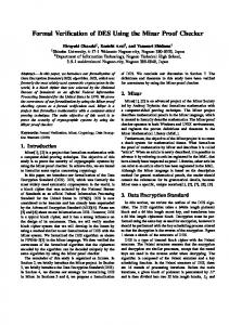
V. E XAMPLE Figure 5 shows the layout of a BHS at an airport. From the 48 check-in lines A , B and the transfer gate F , domestic and international bags enter the BHS. In this BHS, only international bags have to be screened, and thus, are considered uncleared. The bags from the check-in block A are identified by the automatic tag reader (ATR) C , and then transported to the lower main line E of the BHS, whereas bags from check-in blocks B , and transfer bags F are scanned at the ATR D , and thereafter fed into the upper main line G . In case a tag could not be identified by the ATR, these bags are routed to the manual encoding station H , and subsequently fed back into the upper main line of the BHS. Owing to the fact that domestic bags bypass checkedbaggage-screening (CBS) M , they are routed to the lower main line by taking link I ; if this link is too populated, these bags have to take the link K . With this, domestic bags take the outer loop and are routed to the inner makeup carousels N . In contrast, uncleared international bags are routed to one of the two CBS stations M by using the two before mentioned links. If the access to the inner CBS station L is too populated, incoming bags are assigned to the outer CBS station. However, if a bag could not be cleared automatically, this bag is transferred to the screening station P for manual inspection. All cleared international bags are routed to the outer two make-up carousels O . From the make-up carousels, the bags are transported to their departing aircraft. The overall MHS network consists of 364 MHS elements, including, amongst others, 233 conveyors, 55 mergers, and 11 pushers. The whole MHS network could not be verified without partitioning due to state space explosion. However, with the compositional approach presented in this paper, a number of safety-critical properties with regard to routing functionality have been proven automatically using the proposed compositional verification method (cf. Section IV), e.g. no uncleared international or unidentified bags can reach a plane; only domestic bags reach the inner makeup carousels and only international ones the outer make-
P
N
O F
M
H
G
L
I
Uncleared bags
D
Domestic bags E
International bags ATR read failure
K C
A
B
Fig. 5.
Layout of a BHS at an international airport
up carousels; only uncleared bags arrive the CBS stations; only unidentified bags are manually scanned. Therefore, the network has been split up into 13 subnetworks. The only feedback loop that had to be resolved is the outer loop; it has been cut between F and G . The overall verification took 210 seconds (Intel Core
[email protected], 4GB RAM, Windows 7, NuSMV 2.5.3). By increasing the number of subnetworks to 83, the verification time has been further reduced to 15 seconds. This suggests, at first sight, to split up the MHS network into as many subnetworks as possible. However, it has to be taken into account that false negatives can occur if the routing strategy in a subnetwork depends on MHS elements outside of this subnetwork. Thus, if possible, all MHS elements affecting the routing in a subnetwork should be in this subnetwork. This case study shows that with the discussed approach, important properties of the BHS can be proven automatically in a reasonable amount of time. VI. C ONCLUSION This paper presented an approach to prove the routing in MHS by compositional verification. The application of the approach has been shown using a real-world example. Experimental results are promising as the approach scales well with the size of the MHS network. Furthermore, the approach has advantages over simple routing graph analysis because complex sequential routing strategies are also taken into account. Current research focusses on automatic partitioning of MHS networks into subnetworks, where the size of the subnetworks is adjusted dynamically with regard to routing strategies, and the time and/or memory needed by the model checker. Additionally, when possible, proofs of subnetworks should be carried out in parallel. Therefore, topological sorting can be applied. Moreover, the discussed compositional
verification approach will be extended to prove not just routing but arbitrary properties of MHS. R EFERENCES [1] E. M. Clarke, O. Grumberg, and D. A. Peled, Model checking. The MIT Press, 1999. [2] H. Chen, K. Labadi, and L. Amodeo, “Modeling, analysis, and optimization of logistics systems petri net based approaches,” in Proc. Int. Conf. Service Systems and Service Management, 2006, pp. 575 –582. [3] B. D¨udder, G. Follert, and M. Roidl, “Model Checking in multiagentengesteuerten Materialflusssystemen,” Technical University Dortmund, Tech. Rep. 817, 2008. [4] M. Hirsch and M. Zarbock, “Model-Checking eines Materialflusssystems mittels UPPAAL und SMV,” Bachelor Thesis, University of Paderborn, 2002. [5] R. Meolic, T. Kapus, and Z. Brezoˇcnik, “Model checking: A formal method for safety assurance of logistic systems,” in Proc. 2nd Congress Transport — Traffic — Logistics, 2000, pp. 355–358. [6] F. de Renesse and A. Aghvami, “Formal verification of ad-hoc routing protocols using SPIN model checker,” in Proc. 12th IEEE Mediterranean Electrotechnical Conf., 2004, pp. 1177–1182. [7] D. Camara, A. Loureiro, and F. Filali, “Methodology for formal verification of routing protocols for ad hoc wireless networks,” in Proc. IEEE Global Telecommunications Conf., 2007, pp. 705–709. [8] T. Klotz, B. Straube, E. Fordran, J. Haufe, F. Schulze, K. Turek, and T. Schmidt, “Toward verification of material handling systems,” in Proc. IEEE 9th Int. Conf. Industrial Informatics, 2011, pp. 218–223. [9] ——, “An approach to the verification of material handling systems,” in Proc. 16th IEEE Int. Conf. Emerging Technologies and Factory Automation, 2011. [10] J. E. Hopcroft and J. D. Ullman, Introduction to automata theory, languages, and computation. Addison Wesley, 1979. [11] A. Pnueli, “In transition from global to modular temporal reasoning about programs,” in Logics and models of concurrent systems. Springer-Verlag, 1985, pp. 123–144. [12] O. Grumberg and D. Long, “Model checking and modular verification,” in CONCUR ’91, ser. LNCS, 1991, vol. 527, pp. 250–265. [13] J. Cobleigh, D. Giannakopoulou, and C. Pasareanu, “Learning assumptions for compositional verification,” in Tools and Algorithms for the Construction and Analysis of Systems, ser. LNCS, 2003, vol. 2619, pp. 331–346. [14] A. Cimatti, E. M. Clarke, E. Giunchiglia, F. Giunchiglia, M. Pistore, M. Roveri, R. Sebastiani, and A. Tacchella, “NuSMV 2: An opensource tool for symbolic model checking,” in Proc. 14th Int. Conf. Computer Aided Verif ication, 2002, pp. 359–364. [15] “nusmv-tools web site,” http://code.google.com/a/eclipselabs.org/p/ nusmv-tools/, visited June 2012.