Jan 27, 2006 - automobile is a challenge, but there is also a very ... meantime by airborne/automotive/train systems ... fulfilled due to certification reasons.
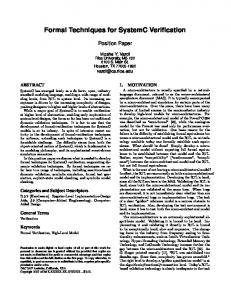
Formal Verification Techniques in a Model-Based Development Process based on TargetLink generated C-Code Dr. Udo Brockmeyer1, Guido Sandmann1, Michael Beine2 1: OSC – Embedded Systems AG; Industriestr. 11; 26121 Oldenburg; Germany 2: dSPACE GmbH Technologiepark 25 33100 Paderborn; Germany Abstract: The numbers of electronic devices in modern automobiles increased enormously within the last few years. Not only the raising number of the Embedded Control Units (ECUs) within one automobile is a challenge, but there is also a very strong increase in functionality in every single ECU. These facts lead to an exponential boost of complexity regarding intra- and inter-ECU behavior. Development of these systems is only manageable if accurate and sophisticated processes are implemented allowing development engineers to deal with this enormous complexity. Those processes provide a means to deliver the devices under hard time and cost constraints. The Model-Based Development process is an approach that allows engineers to graphically specify the behavior of a system and to simulate and execute it in a very early development stage. The tool environment MATLAB®/Simulink®/ Stateflow® offered by TheMathworks is a wide spread modelbased development tool for designing control applications for different industrial domains such as automotive, aerospace or rail systems. Once a model-based development process has been established, engineers are able to apply new technologies and tools to enhance and shorten product development cycles, e.g. by introducing Automatic Model Validation based upon formal verification technology and Automatic Production Code Generation. 1. Model-based Development Process A very promising and quickly spreading approach for the development of embedded systems software is the so-called conceptual model-based design process as supported by the Matlab/Simulink/Stateflow Tools. Its nature is outlined in Figure 1. Requirements given, for instance in a requirements document, are translated first in a formal specification (Simulink/Stateflow Model) representing the system under design. Such specifications are still expressed in a very abstract fashion just capturing relevant functional and safety-critical requirements, but still hiding implementation details like physical characteristics of the concrete hardware or software instance, for example, of a prototype. By formally modeling and specifying a design, formal verification technologies can be used to completely validate ERTS 2006 – 25-27 January 2006 – Toulouse
whether this formal design specification meets its intended requirements. Hence, verification products such as EmbeddedValidator offer specialized formal-isms for expressing requirements like “the system produces certain output values three steps after having seen some input valuations” in a way a model checker understands them. Performing a formal verification task thus means validating a formalized requirement against a design’s formal
Figure 1: Automatic Model Validation and Automatic Code Generation in a Model based specification. When all listed requirements are met by a design’s formal specification – the Simulink/Stateflow model – then this version of the model will be sometimes referred to as ReferenceModel. Within a model-based design process, subsequent development steps then are based upon this Reference-Model. Such a formally verified Reference-Model shows some interesting characteristics. • Only very few modeling flaws survive the formal verification activities • Formal verification requires consistent and unique requirements. Hence, requirement specifications will be of higher quality after this phase • The specification model will be much more complete and very mature The impact of putting emphasis on early development stages is well-understood in the meantime by airborne/automotive/train systems industries. Spending more time in early stages of a development processes increases quality of the overall product, makes subsequent design stages much more efficient, and in particular reduces overall costs in order to fix late-found bugs or to
Page 1/5
correct requirements. Detecting design flaws early improves the overall process. Commercially available tools used to map informal specifications to a formal one within a model-based development process are Matlab/Simulink/Stateflow. EmbeddedValidator uses the TargetLink production code generator from dSPACE for obtaining C-code which then is translated for use within the verification engine. Currently, this application of TargetLink is not completely hidden to the user. However, if a user already applies TargetLink in his process, this EmbeddedValidator approach is indeed beneficial, as formal verification can then be viewed also as production code verification, which is closer to the concrete instance of the ECU. To complete the discussion of Figure 1 above, a verified Reference-Model is a great artifact for the application of model-based Automatic Test case Generation (ATG). Test vectors computed from such a Reference-Model can be used to per-form automated functional as well as white-box testing of the software that implements the specification model. A more detailed discussion of this promising technology is beyond the scope of this paper. Just to mention here that formal verification and ATG nicely fit into processes in order to improve verification and validation activities. 2. Automatic Model Validation Automatic Model Validation offers a technology for performing model-based automatic formal
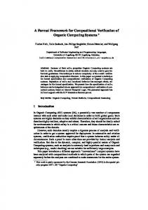
verification by model checking for reactive embedded systems designed using Matlab/Simulink/Stateflow. In contrast to conventional testing approaches, the model checking technology is fully automatic and complete even in mathematical sense, meaning that it can detect every logical design flaw and error within a model under consideration. Model checking analyzes a system regarding arbitrary input scenarios and can thus be viewed as a “complete test” that is performed against a formally specified requirement. Such requirements can be simple boolean expressions such as “an error state is never reached” or more sophisticated ones expressing temporal and causal properties like “an output is set only after certain input values have been observed before”. The result of a model checking run is either “true”, meaning that the model meets its specification, or it returns “false”, meaning that the implementation violates the requirement under validation. In the latter case, the model checker also returns a witness trace representing this violation. EmbeddedValidator offers different visualization views for such traces. First to mention waveform displays, but also Matlab m-scripts allowing users to simulate a problematic situation in Matlab’s simulation environment. If witness traces are found by a model checker then they have minimal length. This means that it uncovers errors with a minimal number of simulation steps and randomly picks an arbitrary
Figure 2: Workflow of Automatic Model Validation by using EmbeddedValidator
ERTS 2006 – 25-27 January 2006 – Toulouse
Page 2/5
representative. A model checker explores the system in a forward manner, terminating whenever the first error is encountered. This is why shortest paths are returned. Appling model checking will be mandatory in near future development processes coping with complex functional and safety critical systems, where high safety-integrity levels like SIL-3 and higher must be fulfilled due to certification reasons. Domain specific safety standards as DO-178B for Airborne Systems require al-ready today application of these technologies in order to produce products with very high reliability. But even in areas where lower safety levels apply, model-checking offers great benefits in order to achieve higher quality systems in shorter time and also containing less errors.
interface objects, and Stateflow states of a model. After having defined a system state, it is a pure push button task to execute the analysis. Drive-toConfiguration check is another analysis possibility. Here, users do not define a boolean formula over arbitrary design objects but only Stateflow state variables. This capability allows checking whether a basic state configuration in a parallel and hierarchical model is dynamically reachable. As result of an EmbeddedValidator run, an executable Matlab m-script will be automatically generated driving a Simulink/Stateflow design in a desired state by using the Simulink/StateflowDebugger. Besides m-scripts, which use Simulink/ Stateflow simulation facilities a waveform visualization of detected traces is offered.
2.1. Use Cases for Automatic Model Validation Currently, the debugging and analysis task of a model under development is a hard and timeconsuming process. The designer has to execute the model by using a simulator in order to provide the right input sequence to reach a critical design state. If a design is a complicated piece of software it is a hard job for a human being to set the right input sequences in order to reach the desired sys-tem state to debug the reactive system. Also, control dominated systems usually have deep dependencies which could not be fully captured by designers. The consequence of the enormous increase of complexity together with the increasing time-tomarket pressure is an inherent growing error rate. Due to the huge amount of functionality that is integrated in embedded control units today’s designers and testers can not ensure the correctness under all environmental circumstances by just applying conventional testing methods. EmbeddedValidator supports different use cases concerning development of embedded control units with state-of-the-art validation techniques based on formal methods.
2.3. Model Certification Formal verification of functional and safety requirements is the key motivation for introducing model checking based verification technology into a model-based development process. The qualitative argument for model checking against testing comes into play: only this mature technique will find all possible attacks against a Simulink/Stateflow design regarding specified requirements. By checking all possible input valuations a model checker tries to uncover design flaws even for border cases conventional tests might not have revealed. Most common functional and safety-critical properties can be formulated easily by using the provided pattern template library. Requirements a model checker should certify need to be formally specified. Particularly, such requirements must capture temporal aspects such as “three steps after feeding certain inputs to the system, some reactions on the output interface take place”. There are several different ways to specify temporal requirements which have been proposed in the past. For ease of use in EmbeddedValidator, OSC offers a library of predefined patterns for requirement specifications. A pattern is intended to be selfexplaining by its name and the user is not confronted with internal implementation details of these patterns. Further, patterns are designed for broadening recognition of temporal requirements, shall prevent ambiguities in their interpretation, and are highly optimized for usage within a model checker. The library itself captures a broad range of common and often used temporal requirements that can be instantiated by the user for applying them to their designs. Instantiations can simply be done by setting certain pattern-parameters and property bindings.
2.2. Robustness Checks & Standard Analyses Robustness Checks and Standard Analyses subsume a list of predefined analyses that supports the user with the development of robust models. The Range-Violation-Check enables a user to dynamically check for range violations, i.e. if there exists a run in which an overflow respectively underflow for a certain variable occurs. This analysis is based on range constraints for variables as specified by a user. The Drive-to- capabilities allow a user to automatically compute an input vector that enters a given system state at its end, if this state is indeed dynamically reachable. EmbeddedValidator offers different possibilities to the user for specifying a desired system state. A general input scheme called Drive-to-Property allows users to specify any possible system state, which can be ex-pressed by a boolean formula ranging over variables, including ERTS 2006 – 25-27 January 2006 – Toulouse
3. Automatic Code Generation Next the existing model has to be transferred into C code and implemented on the ECU. Using automatic code generation for this step is natural and has be-
Page 3/5
come common practice once the software design is available as a model. In contrast to earlier versions of code generators today’s methods of code generation are mature enough to bridge the gap between model based function de-sign and production quality ECU code.
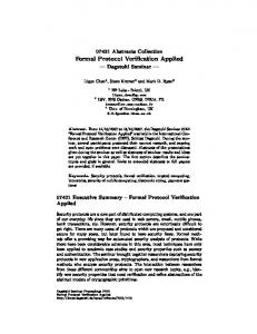
A major advantage of using model-based design methods and tools is the capability of early verification by means of simulation. TargetLink supports different simulation modes which allow the correctness of the implementation, i.e. the code generated by TargetLink, to be tested directly. This
Figure 3: Model-, Software- und Processor-in-the-Loop-Simulation Code generators like TargetLink are capable of generating highly efficient and reliable C Code from well developed models. Using automatic code generation can significantly reduce development times and at the same time increase software quality and eliminate common human programming errors. TargetLink, the production code generator from dSPACE, is seamlessly integrated into MATLAB and allows reliable conversion into C code of existing software de-signs that are available as Simulink/ Stateflow models. 3.1. Code-Characteristics The code generated by TargetLink can well match human programmer’s efficiency in terms of memory consumption and execution speed since TargetLink has been specifically designed and developed for production coding. Numerous benchmarks and user experience reports show that in most cases TargetLink is within a narrow range of what the human programmers produce. Still TargetLink code can be subjected to code inspections and reviews. Target-Link code is well readable and well commented, enabling the user to go back from the code to the model. Unnecessary macros, function calls, cryptic naming etc. are avoided. Comprehensive configuration options give the user full control over variable, function and file naming, as well as the flexibility of partitioning the code into functions and files to keep the structure logical and manageable. 3.2. Test and Verification
ERTS 2006 – 25-27 January 2006 – Toulouse
is done by comparing simulation results with results from reference simulations, frequently referred to as model-in-the-loop simulations. This verification can be performed stepwise: •
First, the generated code is compiled with a host compiler and executed on the host PC; this is also known as software-in-the-loop simulation.
•
Then simulation is performed on an evaluation board equipped with the target processor. Therefore the generated code is compiled with the actual target compiler; this simulation mode is called processor-in-the-loop simulation. In all simulation modes TargetLink allows signal traces of block outputs to be logged. These signal traces can be saved and plotted on top of each other, thus providing direct visual feedback and allowing further analysis. SIL and PIL simulation are complemented by code coverage analysis. The cover-age types currently supported are statement and decision coverage. All this means that extensive support is given to the unit or module testing phase, including model parts that are generated incrementally. 4. Conclusion It is inevitable that embedded software industries in airborne, train, and automotive domains will eventually mature, and catch up with other industries such as the computer hardware industry. Soon, it will be state-of-the-art that model-based development processes are established and exercised. If we also consider that the current strong trend to automation of safety-critical functions
Page 4/5
requires stringent application of safety standards — which in turn demand the application of formal methods in general and formal verification in particular — then it will become common practice for embedded software engineers and test engineers to develop and verify their software using model checking. Benefits of this technology are obvious: design flaws are detected early in the overall process. The quality of specification models increases. These improvements boil down to significant cost reductions in the development process. Formal verification is complemented by Automatic Code Generation. TargetLink as a state of the art production code generator allows producing efficient, reliable, and highly optimized code from the formal verified models by avoiding manual coding errors. The usage of both technologies is a big step towards error and cost reduction within the development process of embedded systems.
ERTS 2006 – 25-27 January 2006 – Toulouse
Page 5/5