Apr 15, 1995 - University of Maryland. College Park, MD 20742 ... With regard to helicopters, only limited work on dam- ... on health monitoring of helicopter rotor-system faults ...... 500. 0. Moisture. Loss of '~isadjusted' Damaged ' Damaged '.
FORMULATION OF A ROTOR-SYSTEM DAMAGE DETECTION METHODOLOGY ,495- 26613
Downloaded by INDIAN INSTITUTE OF SCIENCE on June 13, 2016 | http://arc.aiaa.org | DOI: 10.2514/6.1995-1230
Ranjan G angulit
David Haas 5
Inderjit Chopra 4
Sea Based Aviation Office David Taylor Model Basin Carderock Division Naval Surface Warfare Center Bethesda, MD 20084
Center for Rotorcraft Education and Research Department of Aerospace Engineering University of Maryland College Park,MD 20742
Abstract A rotor-system damage detection methodology is formulated for an articulated rotor in hover, and in forward flight. Damages are represented by changes in mass, stiffness, damping and aerodynamic properties of the rotor blade. A rotor aeroelastic analysis based on finite element discretization in space and time, and capable of modeling dissimilar blades, is used to simulate the undamaged and the damaged rotor. Changes in rotor system behavior are identified for the selected faults and tables of rotor system diagnostics are compiled.
'
Nomenclature thrust coefficient lag damper constant longitudinal, lateral and vertical hub forces rolling, pitching and yawing hub moments nurnber of blades rotor radius kinetic energy strain energy lag deformation of blade flap deformation of blade virtual work variation 'Presented at the 36th Structures, Structural Dynamics and Materials Conference and Adaptive Structures Forum, April 1015, 1995. t ~ e s e a r c hAssociate, Member AIAA t~rofessorand Director, Fellow AIAA § ~ e r o s ~ a Engineer, ce Senior Member AIAA 'Copyright @ 1995 by the American Institute of Aeronautics and Astronautics, Inc. All rights reserved.
shaft tilt angle difference between damaged and undamaged quantity advance ratio solidity ratio torsional deformation of blade shaft roll angle azimuth angle, time blade rotating frequencies rotation speed collective pitch cyclic pitch change in phase angle damaged and undamaged quantity fuselage and rotor quantity ith cosine and sine component
Introduction The helicopter rotor operates in a highly dynamic and unsteady aerodynamic environment leading to severe vibratory and fatigue loads on many critical components within the engine, transmission, drive-shaft and rotor-system. Repeated exposure to this severe loading condition can induce damage in critical structural components, which, if unchecked, could lead to failure. To address this problem, damage sensitive parts are frequently inspected and often, prematurely replaced. This leads to higher operating and maintenance costs. In addition, excessive downtime of helicopters for inspection/maintenance may reduce availability and even jeopardize the mission. The need for a sizable reduction in the operating costs and for enhancement of flight reliability has prompted attention to the development of rotorcraft health monitoring systerns. In this paper, a mathematical model of the rotor-system is used to examine the system response
Downloaded by INDIAN INSTITUTE OF SCIENCE on June 13, 2016 | http://arc.aiaa.org | DOI: 10.2514/6.1995-1230
of the helicopter due t o selected rotor blade damages. With regard to helicopters, only limited work on damage detection and health monitoring has been reported in the literature, with a primary focus on engine, drive shaft and gear-box components [I]. Reported research on health monitoring of helicopter rotor-system faults is nearly nonexistent. One area that research has been conducted in is rotor system component load monitoring to predict fatigue damaging loads. Both classical 121-[3] and neural network [4]-[5] approaches have been investigated t o predict vibratory loads in rotor system dynamic components from easily measured fixed system parameters. On the other hand, much work on health monitoring has been conducted in the areas of rotating machinery [6] and, more recently, space structures[7]. Researchers in the field of rotating machinery diagnostics have focussed on the vibration signature analysis of machines t o detect possible faults before they become severe [8]-[9]. The objective of these analyses is to diagnose the state of the machine in order to perform preventive maintenance. Monitoring the dynamic behavior of machinery, requires transducers that measure acceleration, velocity and displacement at judiciously selected locations. In some applications, the transducers are mounted permanently and the signal is monitored continuously for on-line health assessment. Potential faults in rotating machinery include shaft cracks, shaft imbalance, misalignment, rotor-to-stator rubbing, loose stationary and rotating parts, poorly lubricated bearings and internal friction, and have been studied by several researchers [6], [9], [lo]-[14]. Shaft cracks represent an important and potentially catastrophic fault in rotating machinery and have received considerable attention. Mayes and Davies [lo], [ l l ] studied the effect of a crack on the vibrational behavior of a turbine rotor in order to develop criteria for the detection of cracks in shafts of turbomachinery from measurements of the dynamic response. Grabowski [12] showed a strong dependence of the dynamic response of the shaft on the location of the crack. The objective of these investigations is t o detect and locate the shaft crack using signals from vibration monitoring sensors.
have integrated vibration analysis with system identification algorithms to produce quantitative damage detection methods [15]. A mathematical model of the undamaged structure, usually correlated with experimental data of the undamaged structure, is used to analyze the vibration response of the damaged structure. The location and extent of the structural damage is monitored through system identification of the vibratory response of the space structure during its service life. Modal parameters such as natural frequencies and mode shapes from a damaged structure can be related to the system mass and stiffness properties of the undamaged structure. Comparison of the mass and stiffness properties between the damaged and undamaged structure identifies the damage location and extent. The feasibility of identifying mode shapes, frequencies and damping of space structures in an onorbit environment has also been addressed [16]. This damage detection approach is equivalent t o a model refinement procedure where system models are updated to bring them closer to test data. Research on model refinement [ I71- [20] has been applied for formulating damage detection algorithms. In addition to vibration monitoring, other nondestructive evaluation methods have been employed to assess the integrity of the structure, including radiographic, X-ray, acoustic emission and ultrasound techniques. These traditional methods show the effective deterioration state of only a local area and do not yield a quantitative measure of the impact of the damage to system behavior [21].
In addition t o rotating machinery, another area of ac-
The damage detection techniques developed in the fields of rotating machinery and space structures, can serve as initial guidance for the more complex rotorsystem damage detection problems. Work on turbine rotors, for example, is not readily applicable to helicopter rotors because helicopter rotors have: (1) flexible and articulated blades in flap and lag (2) variable pitch (3) limited number of blades (typically, two to five) (4) unique nonaxial aerodynamic environment (5) rotation rate much less than turbine rotors and (6) high added damping in the lag mode. Work on space structures is not readily applicable to helicopter rotors because rotors have (1)strong aeroelastic interactions (2) highly flexible rotating blades leading to nonlinearities due t o Coriolis forces and moderate deflections (3) periodic nature of blade response (4) strong modal coupling between blade modes.
tive research in fault detection is space structures. Online health monitoring systems of space structures is important because of their inaccessibility t o ground personnel. Researchers in the space structures field
In the absence of a large database of damaged system response, a key component of a successful damage detection algorithm is an accurate mathematical model,
Downloaded by INDIAN INSTITUTE OF SCIENCE on June 13, 2016 | http://arc.aiaa.org | DOI: 10.2514/6.1995-1230
usually a finite element model, of the system under investigation. Over the past few years, a comprehensive rotor code (UMARC) based on a finite element method is space and time has been developed with the capability t o provide accurate and detailed analysis of a typical helicopter rotor-system [22]. The code has been validated with experimental and flight test data for a wide range of flight conditions and rotor configurations. A specialized feature of the code of direct relevance to damage detection is the capability to model and analyze dissimilar blades. This dissimilarity can be in terms of blade structural, inertial and aerodynamic properties. This paper will focus on three tasks which are the foundations for the development of a rotor-system damage detection methodology. First, a mathematical model of a four-bladed articulated rotor representative of the Sikorsky SH-60 helicopter is developed using UMARC. Selected analytical results from UMARC are compared with results obtained from CAMRAD [23]) as well as with experimental data. Next, the math model is modified t o model selected faults on the rotor-head. Finally, a study is conducted t o assess the impact of the selected faults on the helicopter system behavior.
Formulation The formulation is divided into two parts. The first part summarizes the modeling procedure followed in UMARC. The second part discusses issues about modeling selected faults in UMARC.
the fuselage. Contributions from the rotor can be expressed as a sum of contributions from each blade:
The 6Ub and 6Tb include energy contributions from components which are attached t o the blade, e.g., pitch link, lag damper etc. Finite element methodology is used to discretize the governing equations of motion, and allows for accurate representation of complex hub kinematics and nonuniform blade properties. For a conventional structure, damage induced response depends primarily on the distribution of its structural stiffness, mass and damping properties as well as kinematic relationships (e.g., alignment, free-play). The rotor blade, however, displays strong aeroelastic coupling, and the response is influenced by blade aerodynamic characteristics as well. The aerodynamic environment of a helicopter rotor in forward flight is very complex, involving transonic flow with shocks on advancing blades, stalled and reversed flow on the retreating blades and swept flow on the fore and aft regions of the rotor disk. The blade is exposed to unsteady variations of angle of attack and freestream velocity, varying in both radial and azimuthal directions. UMARC offers a range of aerodynamic models for both airloads computation and wake-induced inflow calculations, including unsteady aerodynamics, dynamic stall model and prescribed and free wake.
Mathematical Model of Rotor-System The helicopter is represented by a nonlinear model of several elastic rotor blades dynamically coupled to a six degree of freedom fuselage. Each blade undergoes flap bending, lag bending, elastic twist and axial displacement. Governing equations are derived using a generalized Hamilton's principle applicable to noncom servative systems:
The 6U, bT and 6W are virtual strain energy, kinetic energy and virtual work, respectively. These virtual variations have contributions from both the rotor and
Modeling Faults
of
Selected
Rotor-System
In order to be detectable, a damage must affect the system response (motion or loads) in a detectable manner. This excludes microcracks, which are too negligible to effect system behavior, as well as catastrophic damage, which may cause destruction of the helicopter. Damages on the rotor blade manifest themselves as changes in structural and aerodynamic properties. This change in blade properties of the damaged blade may result in changes in the rotor system properties. Table 1 lists selected classes of blade damage which can be modeled using changes in the blade inertial, stiffness and damp-
ing properties and in aerodynamic coefficients along the span.
Downloaded by INDIAN INSTITUTE OF SCIENCE on June 13, 2016 | http://arc.aiaa.org | DOI: 10.2514/6.1995-1230
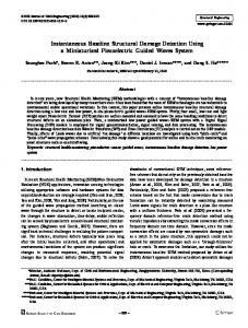
Results and Discussion For results, a $-bladed articulated rotor with properties similar to a SH-60 helicopter is selected (see Table 2). The rotor blade is modeled using seven spatial finite elements along the bladespan (Fig. 1). Six time finite elements with fourth order shape functions are used along the azimuth to calculate the blade response. Blade forces are calculated using a force summation method. The nonlinear blade response equations and the vehicle trim equations are solved simultaneously using a coupled trim procedure. The results are obtained at a CT/a= 0.0726, in hover and at p = 0.3.
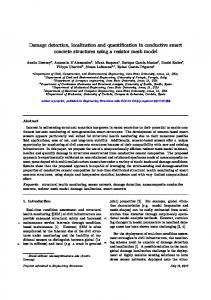
Baseline Results The frequencies of the rotor blade obtained using the finite element model are compared with results obtained from the CAMRAD [23] analysis, and are shown in Table 3. The first flap and lag frequencies are identical, and the higher modes are within close agreement. Results for the push-rod load are compared with flight test data. Prediction of helicopter loads is very dependent on aerodynamic modeling; the current study uses the Scully-Johnson free-wake model [24] and the Leishman-Beddoes unsteady aerodynamic model [25]. As shown in Fig. 2, the push-rod loads predicted by UMARC show close agreement with those obtained using the CAMRAD analytical model as well as with experimental data. The CAMRAD results are obtained from Ref. [2].
Indicators of Rotor-System Damage A schematic view of the 4-blades rotor is shown in Fig. 3(a). It is assumed that blade 1 is damaged and that blades 2, 3 and 4 are undamaged. For the undamaged rotor (assuming perfectly tracked blades), all 4-blades will have the same tip response (magnitude and phase). Also, only 4/rev and 8/rev forces and moments will be transmitted by the undamaged rotor to the fuselage. The forces and moments acting on the rotor hub are defined in Fig. 3(b). Typically, for the damaged rotor, the tip response of
the damaged blade will be different as compared to the undamaged blades. Using advanced micromechanical or optical sensors, it is possible to accurately measure blade tip flap, lag and torsion displacement for each blade. Therefore, any difference between the magnitude or phasing of the tip displacement of the different blades can be used to detect damage. Also vibrations transmitted by the damaged rotor to the fuselage can be monitored using accelerometers. Modern micromechanical sensors based on piezoelectric and optical technologies are able to detect very small changes in vibration of the order on 1OP6g [26]. Such highsensitivity sensors are used in space structures and medical applications and have begun to play an important role in system diagnostics [26]. For a perfectly balanced and tracked rotor, only the Nb/rev forces and moments are transmitted to the rotor hub. In practise, however, there will always be some level of fuselage response at l/rev and at higher harmonics due to the inability to perfectly balance and track a rotor. Typically, a l/rev fuselage response of 0.15 inch per second (ips), equivalent to about 170 lb, is representative of a well balanced rotor. Vibrations in excess of 0.30 ips are considered significant and indicate the need to track and balance the rotor. Approximate thresholds for the moments transmitted to the fuselage can be similarly obtained. Moments below 2500 lb-in are representative of a well tracked and balanced rotor. Moments above 5000 lb-in indicates the need to track and balance the rotor. Similarly, for the blade tip response, most real rotors display some degree of variation in tip displacements between blades even when the rotor is considered to be in a 'tracked' condition. In this study, we assume that variations in tip deflections less than a quarter of an inch, and phase changes less than 10 degrees, are negligible, and changes in elastic twist of less than a quarter of a degree are considered too negligible to be of practical value. Also, if the magnitude of a response quantity is negligible, then the phasing has no practical importance. These guidelines are used in the present study to define quantitative measures of the rotor system response to damage (Table 4). Changes which fall in the moderate to significant range are expected to be useful for diagnostic purposes. The various damages listed in Table 1 are investigated separately. Results for the simulated damages are obtained in hover and forward flight.
Hover Results The axisymmetric hover condition provides for simple interpretation of results. For the hover condition, a uniform inflow distribution is used.
Downloaded by INDIAN INSTITUTE OF SCIENCE on June 13, 2016 | http://arc.aiaa.org | DOI: 10.2514/6.1995-1230
i
I
I
!
i I
The blade lag, flap and elastic torsion tip steady response for the baseline blade are -31.7 inch, 19.91 inch and 0.48 degrees, respectively. Lag deflection is defined negative backwards, flap deflection is positive upwards, and torsion deformation is negative nosedown. Because of the axisymmetric condition, all harmonics of the tip response are zero. Also, all harmonics of the hub forces and moments are zero for the undamaged rotor. For a rotor with one damaged blade, there are l/rev longitudinal and lateral forces in the fixed frame as well as l/rev rolling and pitching moment. The longitudinal and lateral forces are related: (F,'h = F l h ) and (F,'& = -F$). Similarly, the rolling and pitching moments are related: ( M ; h = Mi&) and (M,'& = Mi$). It is therefore sufficient to investigate the longitudinal hub force F x ~ and the hub rolling moment MxH only.
Damage 1: Change in blade mass properties Moisture absorption
Blade mass properties can be changed due to moisture absorption from a humid environment. This problem can be exacerbated by the change in atmospheric pressure between the ground and at high altitude. To simulate moisture absorption, the mass of blade 1 is increased uniformly along the span by 2.74 percent (equivalent to about 0.75 gallons of water). The mass of blades 2, 3 and 4 are fixed at the baseline value. The rotating frequencies of the first nine modes of the damaged and undamaged blades are shown in Table 5. Compared to the undamaged blade, there is negligible change in the first flap and lag modal frequencies for the damaged blade. The higher modes show a negligible reduction in frequencies due to the increase in blade inertia. The blade lag, flap and torsion response for the baseline case and for blades damaged due to moisture absorption are shown in Figs. 4(a), 4(b) and 4(c), respectively. Other damage cases shown in these figures are discussed later. Compared to the undamaged blades, the tip lag and flap response of the damaged blade are reduced by 1.4 inch and 1 inch, respectively, and
the torsion response is reduced by 0.01 degrees. The significant reduction in the flap and lag displacement may be caused by the increase in centrifugal stiffening effect of the heavier damaged blade. For the rotor with one blade damaged due to moisture absorption, the magnitude and phasing of the l/rev longitudinal hub force is shown in Figs. 5(a) and 5(b), respectively, and the magnitude and phasing of the l/rev rolling moment is shown in Figs. 6(a) and 6(b), respectively. The magnitude of the l/rev longitudinal load is about 2400 lb, with a phase angle of 55 degrees. This load is approximately 15 percent of the helicopter weight of 16000 lb and can be easily sensed through accelerometers placed in the fuselage. The l/rev rolling moments is negligible. Loss of trim-mass
Another damage which can be simulated by changing mass properties is the loss of trim mass. To simulate loss of trim mass, the mass of a small damage element of length 1 percent of the blade length, and located at 94 percent of blade-span, is reduced by 25 percent from its baseline value. This amounts to about 1 percent of the total blade mass. Again, the mass of blades 2, 3 and 4 are kept at the baseline value. The loss of trim mass results in a negligible increase in the frequencies of the first three lag modes and the first torsion modes (Table 5). The first flap frequency remains unchanged, and the second, third, fourth and fifth flap frequencies show negligible reduction from the baseline blade. Note that any change in the mass of the blade results in changes in the centrifugal stiffening and the inertia force. Outboard sections of the blade are more influential in changing the centrifugal force than the inertial force. Therefore, the slight reduction in some of the flap frequencies may be due to a reduction in centrifugal stiffening caused by the loss of trim mass becoming more dominant than the reduction in blade inertia. The damaged blade shows a moderate change in blade tip lag and flap response of 0.27 inch each. There is a negligible change in the tip torsion response. The loss of trim mass produces a moderate l/rev longitudinal and lateral vibration of about 300 lbs (Fig. 5(a)). The phasing of the longitudinal force is about 85 degrees (Fig. 5(b)). The magnitude of the l/rev rolling moment is negligible (Fig. G(a)).
Damage 2: Change in blade aerodynamic prop erties
Misadjusted pitch-link Improper adjustment of the pitch-link can lead to a change in the blade zero-lift angle of attack. The lift coefficient of the blade is typically given as Cl = co cia. Assuming that the misadjusted pitch-link causes a reduction in the damaged blade pitch of 1 degree, the change in co is calculated to be -0.1047, over the bladespan of the damaged blade.
Downloaded by INDIAN INSTITUTE OF SCIENCE on June 13, 2016 | http://arc.aiaa.org | DOI: 10.2514/6.1995-1230
+
There is no change in blade rotating frequencies due to damages which change aerodynamic properties only. There is a significant reduction in the tip lag and flap response of 1 inch each, and a negligible change in the tip torsion response of 0.004 degree. (Fig. 4). Note that the rigid pitch of the damaged blade is reduced by 1 degree, which can be easily detected. The reduction in the lag and flap response is primarily caused by the reduction in the blade zero-lift angle of attack, which reduces the aerodynamic forces acting on the damaged blade. Also, moderate l/rev forces are generated in the fixed frame, as shown in Fig. 5 . The longitudinal l/rev force is about 200 lbs in magnitude and has a phase angle of about 20 degrees. The l/rev rolling moment is about 3000 b i n in magnitude (Fig. 6(a)).
Damaged flap Another blade damage which manifests itself through changes in blade aerodynamic properties is a malfunctioning trim flap or tab. Differences in airfoil contour or twist distribution among the blades is sometimes resolved by slightly bending a tracking tab. Trailing edge flaps are also used in active control applications. The deflection of a flap has two effects: the airfoil zero lift angle of attack is changed and a local pitching moment, is produced. To simulate a damaged flap, it is assumed that the damaged blade has a flap with a 5 degree angle whereas the other blades have flaps with zero angle. Therefore, the damaged blade has additional lift and nose-down pitching moment at the tip, causing out-of-track condition. The tab spans the tip element (see Fig. 1) and has a length of about 6 percent of the blade length and a chord of 10 percent of the blade chord. Using data from Ref. [27], for a flap angle of 5 degrees, the change in zero-lift curve slope is obtained as 0.0061 and the change in pitching moment is -0.0084.
The damaged blade shows a reduction in the lag and flap response of 0.46 inch and 0.5 inch, respectively (Fig. 4(a) and 4(b)). There is a negligible nosedown elastic twist of almost 0.1 degrees (Fig. 4(c)). This nose-down twist may be caused by the pitching moment generated by the 5 degree deflection of the flap. Even though there is a negligible increase in lift due to the flap deflection, the nose-down elastic twist causes a larger reduction in blade lift and induced drag forces by reducing the angle of attack, thereby reducing the flap and lag tip deflections for the damaged blade. The l/rev longitudinal force and the l/rev rolling moment are negligible (Figs. 5 and 6).
Damage 3: Change in blade root stiffness prop erties Damaged pitch-control system Reduction in blade root stiffness is used to simulate damage in the rotor control system. For example, damage to the pitch-link, control horn, elastomeric snubber, pitch bearing, etc. can show up as a reduction in the torsion stiffness at the blade root. To simulate these damages, the torsion stiffness of the pitchspring at the root is reduced to yield a reduction in the first torsion frequency from 4.29 (for the undamaged blade) to 4.00 for the damaged blade. This amounts to a 6.75 percent reduction in the torsion frequency of the damaged blade. The damaged blade shows a reduction in the tip lag and flap response of 1.58 inch, and 1.41 inch, respectively, compared to the undamaged blade (Fig. 4). The tip torsion response reduces by 0.15 degrees. The nose-down elastic twist also results in a reduction in aerodynamic loading, and therefore in the flap and lag steady response at the blade tip. The unbalance introduced by the damaged blade with reduced root torsion stiffness causes a significant longitudinal l/rev force of about 400 lbs (Fig. 5(a). The phase of tlte longitudinal force is about 15 degrees (Fig. 5(b)). This damage also causes moderate l/rev rolling moment of magnitude over 4000 lb-in, with almost zero phase angle (Figs. 6(a) and 6(b)).
Damage 4: Change in blade damping properties Damaged lag damper
Downloaded by INDIAN INSTITUTE OF SCIENCE on June 13, 2016 | http://arc.aiaa.org | DOI: 10.2514/6.1995-1230
The mechanical blade damper is represented by a linear lag damper with a damping constant CC of 3000 lb sec/in. The undamaged rotor has all 4 lag dampers attached t o the blades. For the damaged rotor, the lag damper of blade 1 is made inoperative, i.e. CCfor the damaged blade is set equal to zero. For hover, damage to the mechanical lag damper used in this study has no influence on the rotor response and loads. This is because the damper force comes from blade velocity which is zero in the hover condition.
I
Forward Flight Results Forward flight results are obtained using free-wake and unsteady aerodynamic models a t an advance ratio of ,u = 0.3. Figs. 7(a) and 7(b) show the baseline lag, flap and torsion response a t the blade tip for the undamaged blades. The lag response is dominated by the steady component, while the flap response has a significant l/rev harmonic content. Harmonics above l/rev are negligible for the lag and flap response. The torsion response, however, has moderate higher harmonic content, including l/rev, 2/rev and 4/rev harmonics. The trim control angles for the coupled trim solution are shown in Fig. 8. There is a very negligible change in the trim controls between the damaged and undamaged rotors. The steady hub loads for the damaged and undamaged rotors are shown in Fig. 9. The vertical hub force is almost identical for each case, since the trim converges t o the same C T / a . The differences in some of the other steady loads are due to blade damage and are discussed later.
Damage 1: Change in blade mass properties Moisture absorption The blade damaged due t o moisture absorption shows a significant increase in the steady tip lag response of 0.7 inch (Fig. 10(a)). The tip flap response shows a significant reduction in the steady tip flap response of about 0.6 inch and in the l/rev component of 0.3 inch (Fig. l l ( a ) ) . As seen from Figs. 13-18, only the 4/rcv and $/rev forces are transmitted to the fixed frame by the undamaged rotor. However, for the rotor with damage due t o moisture absorption, significant l/rev longitudinal hub force of about 2000 lb is transmitted to the fixed frame (Fig. 13(a)). The damaged rotor also produces a significant 2000 lb lateral force of almost equal magnitude to the longitudinal l/rev force
(Fig. 14(a)). Unlike the longitudinal force, however, the lateral l/rev shows almost no change in the phase angle (Fig. 14(b)). Moderate l/rev vertical force of about 180 lb in magnitude is produced due to moisture absorption with a phasing of about 40 degrees (Figs. 15(a) and l5(b)). Moisture absorption produces moderate 5/rev and lO/rev yawing moments of about 5000 lb-in and 3000 b i n , respectively (Fig. 18(a)).
Loss of trim-mass Loss of trim mass causes a negligible change in the flap, lag and torsion deflection a t the blade tip (Figs. 10, 11 and 12). Significant l/rev longitudinal hub force of about 360 lb is transmitted to the hub by the damaged rotor (Fig. 13(a) with a phase angle of 90 degrees (Fig. 13(b)). A significant lateral l/rev force of about 360 lb is also produced by the damaged rotor (Fig. 14(a)). While the magnitude of this force is identical to the longitudinal force, the phase angle for the lateral force is about zero, in contrast to the 90 degrees phase for the longitudinal force (see Fig. 13(b) and 14(b)).
Damage 2: Change in blade aerodynamic prop erties Misadjusted pitch-link The misadjusted pitch-link produces a moderate increase in the steady lag response of about 0.3 inch (Fig. 10(a)). Significant reduction in the steady flap response of 1 inch is produced with a moderate increase in the l/rev flap response of about 0.4 inch (Fig. l l ( a ) ) . The longitudinal hub force shows a moderate change in the $/rev hub force of just under 200 lb (Fig. 13(a)). There is a significant reduction in the phasing of the 4/rev longitudinal force compared to the undamaged rotor (Fig. 13(b)). The hub rolling moment shows a moderate l/rev moment of about 3000 Ib-in (Fig. lG(a)). The 4/rev rolling moment shows a significant change of phase of about 40 degrees, compared to the 4/rev moment for the undamaged rotor (Fig. 16(b)). The hub pitching moment shows a moderate l/rev component of about 2800 lb-in, and a significant change in the 4/rev component of about 5000 lb-in (Fig. 17(a)). Also, the l/rev pitching moment has a significant phase angle of about 90 degrees, and the phasing of the 4/rev moment changes from 50 degrees for the undamaged rotor to about -20 degrees for the damaged rotor, a significant change of about 70 degrees (Fig. 17(b)). The hub yawing moment shows a significant increase in the 4/rev component of about
6000 b i n (Fig. 18(a)) and a change in phase of about 90 degrees, compared to the undamaged rotor (Fig. 18(b)). For the steady loads, the misadjusted pitchlink results in a significant increase in the steady roll moment of about 40 percent compared to the undamaged rotor (Fig. 9). The steady yawing moment is also increased by about 30 percent.
Downloaded by INDIAN INSTITUTE OF SCIENCE on June 13, 2016 | http://arc.aiaa.org | DOI: 10.2514/6.1995-1230
Damaged flap The damaged flap results in a reduction in the steady flap tip response by 0.8 inches and an increase in the l/rev flap response of 0.8 inches (Fig. 20(a)). The phasing of the 4/rev longitudinal force shows a change of almost 40 degrees, compared to the undamaged rotor (Fig. 22(b)). The vertical hub force shows a moderate l/rev component of about 250 lb with a phase angle of about -70 degrees (Fig. 24(a) and 24(b)) The magnitudes of the hub rolling moment shows negligible change due to the damage, however, the phasing of the 4/rev component shows a change of about 3540 degrees, compared to the undamaged rotor (Fig. 25). The 4/rev pitching moment shows a significant increase in magnitude of about 5000 lb-in, as well as a significant change of phase of about 70 degrees compared to the undamaged rotor (Fig. 26). The 4/rev yawing moment shows a significant increase of about 6000 lb-in (Fig. 27(a)). Also, the phasing of the 4/rev moment changes by almost 90 degrees between the undamaged rotor and the rotor with the damaged flap (Fig. 27(b)). The steady rolling and yawing moment increase by of about 40 and 30 percent, respectively (Fig. 9).
Damage 3: Change in blade root stiffness prop erties Damaged pitch-control system The damaged pitch-control system causes moderate increase in the blade steady lag response of 0.36 inch (Fig. 19(a)). A significant reduction in the steady flap response of 1.36 inch and in a moderate increase in the l/rev and 3/rev flap response of 0.47 inch and 0.4 inch is observed (Fig. 20(a)). The damaged pitch-control also produces a moderate change in the phase of the 3/rev flap response of about 30 degrees (Fig. 20(b)). Looking a t the torsion response, moderate changes in the 3/rev torsion response of about 0.4 degrees is obtained with a moderate phase change of about 30 degrees (Figs 21(a) and 21(b)). The 3/rev elastic twist and the l/rev and 3/rev flap are likely to result in
higher harmonic loads in the fixed frame. For the longitudinal hub force, the damaged rotor produces significant l/rev forces of about 620 lb, as well as moderate 5/rev, 6/rev, 9/rev and lO/rev forces ranging from 200-400 lbs (Fig. 22(a)). The phase angle of the longitudinal 5/rev and 6/rev forces is about -55 degrees and 75 degrees, respectively (Fig. 22(b)). The lateral hub force has a l/rev component of about 620 lb, as well as moderate 5/rev and 6/rev components of 200-250 lbs. The l/rev lateral force has a phasing of about 90 degrees (Fig. 23(b)). The vertical hub force also shows a significant l/rev force of about 410 lbs, as well as moderate 2/rev and 3/rev components of 170-200 lbs (Fig. 24(a)). The l/rev vertical force has a phase of -70 degrees, and the 3/rev component has a phase of -90 degrees. The hub rolling moment shows a significant l/rev component of about 5000 lb-in as well as moderate 2/rev and 6/rev components of magnitude 2500-4000 lb-in (Fig. 25(a)). The phasing of the l/rev rolling moment is about -20 degrees and that of the 2/rev and 6/rev forces are 45 degrees and -15 degrees, respectively (Fig. 25(b)). The hub pitching moment shows a significant l/rev moment of about 5000 Ib-in and a moderate 6/rev component of about 3200 lb-in (Fig. 26(a)). The phasing of the l/rev pitching moment is about -85 degrees and that of the 6/rev component is about 65 degrees (Fig. 26(b)). Also, there is moderate change in the phase of the $/rev pitching moment of about 20 degrees. For the hub yawing moment, a significant 5/rev moment of about 8600 lb and a lO/rev moment of about 5500 lb-in is produced by the damaged blade (Fig. 27(a)). A moderate 6/rev moment of about 2500 lb-in is also produced. While the magnitude of the 4lrev hub moment remains almost unchanged for the damaged blade, there is a significant change in the phasing from about 85 degrees for the undamaged blade to -60 d,egrees for the damaged blade (Fig. 27(b)). The 5/rev moment has a phase of about 15 degrees and the 6/rev of about 60 degrees, respectively. The steady hub loads show an increase in the rolling and pitching moments of about 10 percent, compared to the undamaged blade (Fig. 9).
Damage 4: Change in blade damping properties Damaged lag damper The inoperative lag damper results in a measurable
Downloaded by INDIAN INSTITUTE OF SCIENCE on June 13, 2016 | http://arc.aiaa.org | DOI: 10.2514/6.1995-1230
reduction of the steady tip flap response of about 0.3 inch, as well as moderate l/rev and 3/rev components of 0.5 inch and 0.27 inch, respectively (Fig. 20(a)). The phase change for the l/rev component is negligible, however, the 3/rev flap response shows a moderate change in phasing of about 30 degrees (Fig. 20(b)). The tip torsion response shows moderate change in the 3/rev and 4/rev components of about 0.44 degrees and 0.25 degrees, respectively (Fig. 21(a)). The phase of the 4lrev torsion response also shows a significant phase change of about 95 degrees, ccmpared to the phasing of the undamaged blades (Fig. 21(b)). The 3/rev flap response and 3/rev and 4/rev elastic twist are likely to cause higher harmonic loads in the fixed frame. The damaged lag damper causes a significant l/rev longitudinal hub force of about 720 lb, as well as moderate 5/rev, 6/rev, 9/rev and lO/rev forces ranging from 200-400 lbs (Fig. 22(a)). The phase angle of the l/rev longitudinal force is almost zero (Fig. 22(b)). The 5/rev and 6/rev forces show significant phase angles of -55 degrees and 75 degrees, respectively. The lateral hub force causes a significant l/rev force of about 720 lb, as well as moderate 5/rev and 6/rev forces of about 200 lb each (Fig. 23(a)). The l/rev lateral force has a significant phase angle of about 90 degrees and the 6/rev force has a negligible phase angle of about 12 degrees (Fig. 23(b)). For the vertical hub force, moderate l/rev, 2/rev 5/rev 8/rev and lO/rev components ranging from 175-225 lbs are produced due t o the damaged lag damper (Fig. 24(a)). The l/rev, 2/rev and 5/rev harmonics show a phase angle of -50 degrees, -25 degrees and -20 degrees, respectively (Fig. 24(b)). The phase of the 8/rev and lO/rev forces is zero. The hub rolling moment shows a moderate reduction in the 4/rev harmonic of almost 3500 lb-in (Fig. 25(a)). The hub yawing moment shows significant 5/rev and lO/rev harmonics of about 8500 lb-in and 5500 lb-in, respectively (Fig. 27(a)). There is a negligible change in the magnitude of the 4/rev harmonic component, however, the phase angle changes from about 85 degrees for the undamaged rotor to about -60 degrees for the damaged rotor (Fig. 27(b)).
Rotor System Diagnostics Tables 6 through 9 summarize the results obtained in this study and provide a "diagnostic feature map' for
each type of damage investigated. The symbols are defined in Table 4. In Table 6, results obtained in hover are summarized, and changes in the steady lag, flap and torsion response are indicated, along with changes in the l/rev longitudinal force and rolling moments. Table 7 shows the change in the tip lag, flap and torsion response in forward flight. The numbers in Table 7, next to the symbols, indicate the harmonics of the response. For example, 3 - 0 , shows that the third harmonic is moderate. Table 8 and 9 show the results for the hub forces and moments, respectively. Again, for indicates that the 6/rev component of example, 6- 0, the force harmonic is significant. These diagnostic tables can be used by pattern recognition algorithms to detect damage. They are used to make the conclusions for this study.
Conclusions Selected rotor-system damages are modeled using a comprehensive aeroelastic analysis. The following conclusio~isare drawn by studying the changes in the rotor-system behavior due to different faults, in hover, and in forward flight.
Hover 1. Moisture absorption can cause very significant l/rev longitudinal and lateral forces in the fixed frame, as well as significant changes in the magnitude of the flap and lag response. 2. Loss of trim-mass causes moderate l/rev longitudinal and lateral forces in the fixed frame as well as a significant (almost 90") change in the phase of the l/rev forces.
3. The misadjusted pitch-link causes significant flap and lag tip deflections, as well as moderate l/rev longitudinal and lateral forces. 4. The damaged flap causes moderate changes in flap and lag deflections and negligible l/rev forces and moments.
5. The damaged pitch-control system causes significant l/rev longitudinal and lateral forces and mcderate l/rev rolling and pitching moments, as well as significant changes in the flap and lag deflections. 6. The inoperative lag damper has no effect in hover since blade lag velocity is zero.
Forward Flight
Downloaded by INDIAN INSTITUTE OF SCIENCE on June 13, 2016 | http://arc.aiaa.org | DOI: 10.2514/6.1995-1230
1. Moisture absorption causes significant l/rev longitudinal, lateral and vertical forces, as well as significant changes in the magnitude of the steady flap and lag response. Moderate l/rev flap displacement, as well as 5/rev and l0/rev yawing moments, are also observed.
2. Loss of trim mass causes negligible changes in the blade response and the hub moments, however, significant l/rev longitudinal and lateral forces are observed in the fixed frame. 3. The misadjusted pitch-link causes significant changes in the steady roll and yaw moments, and in the 4/rev pitching and yawing moment. Significant changes in phase of the 4lrev rolling, pitching and yawing moments are also noted. There is also a significant change in the steady flap response, as well as moderate changes in the steady lag, l/rev flap tip dispacements and in the 4/rev longitudinal force and l/rev roll and pitching moments.
4. The damaged flap causes significant steady and l/rev flap displacement, as well as sig~lificant change in the phase of the 4/rev longitudinal force, pitching moment and yawing moment. There is also a significant increase in the steady roll and yaw moment.
5. The damaged pitch-control system causes significant change in the steady flap response and moderate change in the 3/rev flap and 3/rev elastic twist. This higher harmonic elastic twist causes moderate higher harmonic loads for the inplane hub forces and all three moments. Significant l/rev roll and pitching moments are also present. 6. The damaged lag damper causes a moderate change in the steady l/rev and 3/rev flap deflection. It also causes a moderate change in the 3/rev and 4lrev torsion response, leading to moderate higher harmonic loading in the three hub forces and the three hub moments. However, unlike for the damaged pitch-control system, the l/rev roll and pitch moments produced by the damaged lagdamper is negligible.
Acknowledgement The authors thank Kelly McCool for providing data for the SH-60 helicopter.
References [I] Stewart, R.M., "Health and Usage Monitoring Systems," 18th European Rotorcraft Forum, Avignon, France, SP-5, Paper No. 505, September 15-18, 1992. [2] Haas, D.J., and Imber, R., "Identification of Helicopter Component Loads using Multiple Regression," Journal of Aircraft, Vol. 31, No. 4, July 1994, pp. 929-935. [3] Gunsallus, C.T., and Robeson, E., "AH-64A Rotating Load Usage Monitoring from Fixed System Information," AHS Structures Specialist Meeting, Williamsburg, Virginia, 28-30 October, 1991. [4] Haas, D.J., Milano, J., and Flitter, L., "Prediction of Helicopter Control Loads using Neural Networks," AIAA papeer 93-1301, AIAA 34th Structures, Structural Dynamics, and Materials Conference, 19-22 April, 1993, To Appear in the Journal of the American Heiicopter Society. [5] Haas, D.J., Flitter, L., and Milano, J., "Helicopter Flight Data Feature Extraction for Component Load Monitoring," AIAA Paper 94-1308, AIAA 35th Structures, Structural Dynamics and Materials Conference, Hilton Head, SC, 18-20 April, 1994. [6] "The Systems Engineering Approach to Mechanical Failure Prevention," Proceedings of the 47th Meeting of the Mechanical Failures Prevention Group, Virginia Beach, VA, April 13-15, 1993. [7] Kashangaki, T.A.L., "On-Orbit Damage Detection and Health Monitoring of Large Space Structures - Status and Critical Issues," Proceedings of the 32nd Structures, Structural Dynamics and Materials Conference, AIAA, Wasliington, D.C., April 1992.
[8] Genta, Giancarlo., Vibration of Structures and Machines, Spriger-Verlag, New York, 1993, pp. 313-317. [9] Kim, J.H., and Yang, W.J., Dynamics of Rotating Machinery, Hemisphere Publishing Corporation, New York, 1990, pp. 3-35.
[lo] Mayes, I.W., and Davies, W.G.R., "Analysis of Response of a Multi-Fbtor Bearing System Containing a Transverse Crack in a Rotor", ASME Journal of Vibration, Acoustics,
Stress and Reliability in Design, Vol. 106, No. 1, 1984, pp. 134145.
Downloaded by INDIAN INSTITUTE OF SCIENCE on June 13, 2016 | http://arc.aiaa.org | DOI: 10.2514/6.1995-1230
[ l l ] Davies, W.G.R., and Mayes, I.W., "The Vibrational Behavior of a Multishaft, Multibearing System in the Presence of a Propogating Transverse Crack", ASME Journal of Vibration, Acoustics, Stress and Reliability in Design, Vol. 106, No. 1, 1984, pp. 146-153. [12] Grabowski, B., " The Vibrational Behavior of a Turbine Rotor Containing a Transverse CracklnASMEJournal of Mechanical Design, Vol. 102, No. 1, 1979, pp. 140-146. [13] Imam, I., Scheibel, S., Azaro, H., Blanket, R.J., " Development of an On-line Rotor Crack Detection and Monitoring System", ASME Vibration Conference, Boston, 1987. [14] Nelson, H.D., and Nataraj, C., "The Dynamics of a Rotor System with a Cracked ShaftlnASMEJournal of Vibration, Acoustics, Stress and Reliability in Design, Vol. 108, No. 2, 1986, pp. 189-196. [15] Zimmerman, D.C., and Smith, S.W., "Model bfinement and Damage Location for Intelligent Structures,"Intelligent Structural Systems, H.S. Tzou and G.L.Anderson, Editors, pp. 403-452, Kluwer Academic Publishers, The Netherlands, 1992. [16] Kim, H.M., and Doiron, H.H., "On-Orbit Modal Identification of Large Space Structures,"Sound & Vibration, Vol. 26, No. 6, pp. 24-30, June 1992. [17] Zimmerman, D.C., and Widengren, M., "Correcting Finite Element Models using a Symmetric Eigenstructure Assignment Technique", AIAA Journal, Vol. 28, No. 9, pp. 1670-1676, 1990. [18] Baruch, M., and Bar Itzhack, I.Y., "Optimal Weighted Orthogonalization of Measured Modes", AIAA Journal, Vol. 16, No. 4, pp. 346-351. [19] Berman, A., and Nagy, E.G., "Improvement of a Large Analytical Model using Test Data", AIAA Journal, Vol. 21, No. 8, pp. 346-351, 1978. [20] Kammer, D.C., "Optimum Approximation for Residual Stiffness in Linear System Identification", AIAA Journal, Vol. 26, No. 1, pp. 104112, 1988.
[21] Kim, H.M., and Bartkowicz, T.J., "Damage Detection and Health Monitoring of Large Space Structures" Proceedings of the 34th Structures, Structural Dynamics and Materials Conference, La Jolla, California, April 1993, pp. 3527-3533. [22] Bir, G., Chopra, I., et al., "University of Maryland Advanced Rotorcraft Code Theory Manual," UM-AERO Report 94-18, July 1994. [23] Johnson, W., "A Comprehensive Analytical Model of Rotorcraft Aerodynamics and Dynamics. Part 1: Analysis Development," NASA TM 811182, Jun 1980. [24] Scully, M.P., "Computation of Helicopter Rotor Wake Geometry and its Influence on Rotor Harmonic Airloads,"Massachussetts Institute of Technology, ASRL T R 178-1, Mar 1975. [25] Leishman, J.G., and Beddoes, T.S., "A Generalized Model for Unsteady Aerodynamic Behavior and Dynamic Stall using the Indicia1 Method," Journal of the American Helicopter Society, Vol. 36, No. 1, Jan 1990. [26] Hauptmass, Peter., Sensors - Principles and Applications, Prentice Hall, Inc., Englewoods Cliff, New Jersey, 1991, pp. 63-65. [27] Abbot, I, H., and Von Doenhoff, A.E., Theory of Wing Sections, Dover Publications, Inc., New York, 1959, pp. 188-200.
Table 1-Potential R o t o r H e a d D a m a g e
Damage 1
I Blade property I Type of damage I Inertial I Moisture absorption
Simulation of Damage
I uniform increase in blade mass
I Damage to trim mass I reduction in mass at damaged section
I
Downloaded by INDIAN INSTITUTE OF SCIENCE on June 13, 2016 | http://arc.aiaa.org | DOI: 10.2514/6.1995-1230
I
Damage 2
Aerodynamics
Damage 3
Stiffness
Damage 4
Damping
Damaged flap or blade Misadjusted pitch-link Damage in pitch-control system Damage to lag damper
change in lift and pitching moment at damaged section change in CQ over damaged blade reduction in torsion stiffness at blade root reduction in lag damper constant
Table 2-Helicopter P r o p e r t i e s Rotor Radius Flap and Lag Hinge Offset Number of Blades Blade Chord Linear Aerodynamic Twist Cl c d
cm Lock Number Solidity Blade Attachment Point Rotor Tip Speed Helicopter Weight Blade Mass
Table 3
- Baseline
Mode First Lag First Flap Second Flap First Torsion Second Lag Third Flap Fourth Flap
B l a d e R o t a t i n g Frequencies ( p e r rev)
UMARC (7 elements) .271 1.036 2.75 4.29 4.51 5.08 7.84
CAMRAD (Detailed Model) .271 1.O36 2.8 4.34 4.59 4.85 7.55
Percent Difference 0 0 1.78 1.84 1.74 4.74 3.84
Table 4
Downloaded by INDIAN INSTITUTE OF SCIENCE on June 13, 2016 | http://arc.aiaa.org | DOI: 10.2514/6.1995-1230
n
- Quantitative Measures for System Behavior
Measure I Tip flap, lag -(inch) (units) < 0.25 Negligible ~ ~ d e r a t e 0.25-0.50 Significant >0.50
1
Table 5
*
Tip torsion (degrees)
I
< 170
< 0.25
(
Phase
1 Symbols [I
< 2500 1
< 10
1
Moments (bin)
Forces (lb)
I (degrees) 1
-
170-340 >340
0.25-0.50 >0.50
- Frequencies for Damaged Blades
Mode
Undamaged
Moisture Absorption
Loss of Trim Mass
Damaged Pitch-Control
First Lag First Flap Second Flap First Torsion Second Lag Third Flap Fourth Flap Fifth Flap Third Lag
.271 1.036 2.75 4.26 4.51 5.08 7.84 11.61 12.04
0.271 1.O36 2.74 4.23 4.48 5.051 7.80 11.48 11.89
.272 1.036 2.74 4.30 4.52 5.07 7.83 11.56 12.04
.271 1.O36 2.75 4.00 4.51 5.08 7.84 11.61 12.04
Table 6 - Rotor System Diagnostics in Hover Av Aw A$ IF:HI Damage L F : ~ (M:HI Moisture Absorption 0 0 0 0 o o o Loss of Trim Mass 0 o o o Misadjusted Pitch-Link 0 0 o o Damaged Flap o o Damaged Pitch-Control 0 0 0 Damaged Lag Damper
--
N
-- -N
Table 7 - Rotor System Diagnostics in Forward Fli Av I Lv Aw Damage 0-0 I 0-0,l-o Moisture Absorption Loss of Trim Mass Misadjusted Pitch-Link Damaged Flap Damaged Pitch-Control Damaged Lag Damper
I I
-
%
-
-
LMiH N
N
-N
1
n b l e 8 - Rotor System Diagnostics in Forward Flight Damage 1 I, F--TxI Moisture Absorption 1-0 Loss of Trim Mass Misadjusted Pitch-Link Damaged Flap 4- 0
-
Hub Forces
Downloaded by INDIAN INSTITUTE OF SCIENCE on June 13, 2016 | http://arc.aiaa.org | DOI: 10.2514/6.1995-1230
8
Thble 9 - Rotor Svstetn Diagnostics in Forward Flight Damage I I M z ~ r l L h f z ~ I h f v ~ I L fiI, ff I Moisture Absorption Loss of Trim Mass Misadjusted Pitch-Link 0-0,l-o 1-0,4-0 1-4-0 4-0 Damaged Flap 4- o 0-0 44-0 Damaged Pitch-Control 1-0,O-2-6-0 1-3-0,2-0 1-O,6-0 1-6-0,4-o Damaged Lag Damper 4-0
N
-
-
-
N
N
N
-
o
-
1-0
N
N
N
- Hub Momel I M ~ HI 5-0,10-o N
0-0, 4-0 0-0,4-o 5-10-0,O-6-0 5-10-0
1-0
-UMARC
- - - - - CAMRADIJA Flight Test
10
Loads1100 Ibs
:
Downloaded by INDIAN INSTITUTE OF SCIENCE on June 13, 2016 | http://arc.aiaa.org | DOI: 10.2514/6.1995-1230
6--
Fig. 1 Finite element model of rotor blade
Velocity (knots) Fig. 2 Cornparsion of pushrod load predictions obtained from UMARC with CAMRAD and flight test data
Blade 2
Fig 3(a). Schematic view of damaged and undamaged blades
Downloaded by INDIAN INSTITUTE OF SCIENCE on June 13, 2016 | http://arc.aiaa.org | DOI: 10.2514/6.1995-1230
LEFTSIDE VIEW
REAR VIEW
Fig. 3(b) Definition of rotor forces and moments 2.0
1.5
AV (inch)
1.0
AW
(inch)
-0.5
0.5
0.0
-0.5 Moisture Absorption
Loss of Trim Mass
Misadjusted Damaged Damaged Pitch-Link Flap Pitch-Contr
Fig. 4(a) Change in tip steady lag deflection of damaged blade lrom the undamaged blade, for simulated rotor faults
j Mo . .stJre . . : Loss . . of. . ,M~saa,ustea . . . . ; Damagea . . . . Damaged : . . . . I Absorptton
Trim Mass
P tch-L*nk
Flap
P~tch-Control
Fig. 4(b) Change in lip steady flap deflection of damaged blade fmm the undamaged blade, for simulated rotor faults
Downloaded by INDIAN INSTITUTE OF SCIENCE on June 13, 2016 | http://arc.aiaa.org | DOI: 10.2514/6.1995-1230
-0.20
Moisture ' Loss of Absorption Trim Mass
Moisture ' Loss of ' ~isadjustebDamaged' Damaged Absorption Trim Mass Pitch-Link Flap Pitch-Control
'
isa adjusted Pitch-Link
Damaged ' Damaged ' Flap Pitch-Control
Fig. 6(a) Magnitude of the l/rev rolling moment transmitted by the damaged rotor to the fixed frame
Fig. 4(c) Change in tip steady elastic twist of &ma ed blade from the undamaged blade, for simulated rotor ?auks
Steady 'Ihrust = lhOOO Ib
2000 5
Phase of
lFxHtPl1500 (Ib)
MxHlP (deg)
1000
0
-5
500 -1 0
0
I
Moisture Loss of '~isadjusted' Damaged ' Damaged ' Absorption Trim Mass Pitch-Link Flap Pitch-Control
Moisture Loss of Misadjusted Damaged Damaged Absorption Trim Mass Pitch-Link Flap Pitch-Control
Fig. 5(a) Magnitude of longitudinal llrev force transmitted by the damaged rotor to the fixed frame
Fig. 6(b) Phasing of llrev rolling moment transmitled by the damaged rolor to the fixed frame
80
I
60
v,w
Phase of
(inch)
FxH1P(deg)40
20
I 0
Moisture Loss of ' t is adjusted Damaged ' Damaged Absorption Trim Mass Pitch-Link Flap Pitch-Control Fig. 5(b) Phasing 01 llrev longitudinal force transmitted by the damaged rotor to the fixed frame
I Iarmonics Fig. 7(a) Harmonics o f the tip flap and lag r e s p o n s e of the blades o f the undamaged r o t o r
0.8 0.6
AV (inch)
Moisture absorption Loss of trm mass
0.4
Misadjusted pitch-link
0.2 0.0
Harmonics
Downloaded by INDIAN INSTITUTE OF SCIENCE on June 13, 2016 | http://arc.aiaa.org | DOI: 10.2514/6.1995-1230
Harmonics
Fig. 10(a) Chan e in harmonics of the tip la response between Amaged and undamaged b i d e s
Fig. 7(b) Harmonics of tip torsion response of blades of the undamaged rotor
Undamaged rotor Moisture absorption Loss of trim mass Misadjusted pitch-link Damaged flap Damaged pitch-control Damaged lag damper
2
1
5
4
Fig. 10(b) Change in phasing of the harmonics of the tip lag response between damaged and undamaged blades
Fig 8. Control angles for trimmed rotor
AW (inch)
0.0 Mo~stureabsorption Loss of trlm mass M~sadjustedpltch-lmk
-1.5
Fig 9. Steady hub loadsfor damaged and undamaged rotor, normalized with undamaged rotor values
3 Harmonics
0
1
2 3 Harmonics
4
5
Fig. 11(a) Change in harmonics of the tip flap response between damaged and undamaged blades
2000 Undamaged rotor
1500
Moisture absorpt~on Loss of trlm mass Mlsadjusted pitch-lmk
Phase between w and wU
,
(deg)
Downloaded by INDIAN INSTITUTE OF SCIENCE on June 13, 2016 | http://arc.aiaa.org | DOI: 10.2514/6.1995-1230
- 8 ~ . . . . ~ . . . , ; . . . . ; . . , . ; . . . , 1 2 3 4 5 Harmonics Fig. 11(b) Change in phasing of the harmonics of the tip flap response between damaged and undamaged blades
13
Harmonics Fig 13(a). Magnitude of harmonics of longitudinal hub force for damaged and undamaged rotor
Moisture absorpt~on Loss of trlm mass Mlsadjusted p~tch-lmk
Undamaged rotor Moisture absorpt~on Loss of trim mass Misadjusted pitch-lmk
0 1 2 3 4 5 6 7 8 9 1 0
-90
Harmonics
Harmonics Fig. 12(a) Change in harmonics of the tip torsion response between damaged and undamaged blades
Fig 13(b). Phasing of harmonics of longitudinal hub force for damaged and undamaged rotor
2000 Undamaged rotor
1500
Moisture absorption Loss of trlm mass Misadjusted pitch-link
Moisture absorpt~on Loss of trlm mass Mlsadlusted p~tch-lmk
-150
Harmonics Fig. 12(b) Change in phasing of harmonics of the tip torsion response between damaged and undamaged blades
Fig 14(a). Magnitude of harmonics of lateral hub force for damaged and undamaged rotor
Undamaged rotor
6
1
I
I
I
Downloaded by INDIAN INSTITUTE OF SCIENCE on June 13, 2016 | http://arc.aiaa.org | DOI: 10.2514/6.1995-1230
- 9 0 4 1 1 2 1 3 4
Moisture absorption Loss of trim mass Misadjusted pitch-link
,
I
I
5 6 7 Harmonics
,
1
8
.
I
1
9
Harmonics Fig 16(a). Magnitude of harmonics of rolling hub moment for damaged and undamaged rotor
Undamaged rotor Moisture absorption Q Loss of trim mass Misadjusted pitch-link
600 400
Undamaged rotor Mo~stureabsorption Loss of trim mass Misadjustedpitch-link
200 0
Undamaged rotor Moisture absorption Loss of trim mass Misadjusted pttch-link
.
10
Fig 14(b). Phasing of harmonics of lateral hub force for damaged and undamaged rotor
800
6
1
2
3
4
5
6
7
8
9
1
0
Harmonics Fig 15(a). Magnitude of harmonics of vertical hub force for damaged and undamaged rotor
Harmonics Fig 16(b). Phasing of harmonics of hub rolling moment for damaged and undamaged rotor
Undamaged rotor Moisture absorption Loss of trim mass Misadjusted pitch-link
Undamaged rotor Moisture absorption Loss of tnm mass Msadysted p~tch-knk
Harmonics Fig 15(b). Phasing of harmonics of vertical hub force for damaged and undamaged rotor
Fig 17(a). Magnitude of harmonics of hub pitching moment for damaged and undamaged rotor
Cfa = 0.0726, p=0.3 60
Damaged Rap Damaged pitch-control
0.6
30
Damaged lag damper
Phasing of 0 My,(deg)
0.4
AV (inch) Undamaged rotor Moisture absorption Loss of trim mass Misadjusted pitch-link
- 9 0 1 . ; . I . ; . ; .11;. 1 2 3 4 5 6
; .
7
f
8
.
I . ; . 9 1 0
I Harmonics
Downloaded by INDIAN INSTITUTE OF SCIENCE on June 13, 2016 | http://arc.aiaa.org | DOI: 10.2514/6.1995-1230
Harmonics Fig 17(b). Phasing of harmonics of hub pitching moment for damaged and undamaged rotor
15000
'
Mz~'
(Ib-in)
10000
Undamaged rotor Moisture absorption Loss of trim mass M~sadjustedpitch-link
Fig. 19(a) Chan e in harmonics of the tip la response between ?amaged and undamaged btdes
Phase v . and v
-50 f
'-1mi so00
.
a
Damaged flap Damaged pitch-link Damaged lag damper
C,/o = 0.0726, p S . 3 0 Harmonics Fig. 19(b) Change phasing of the harmonics of the tip lag response between damaged and undamaged blades
Fig 18(a). Magnitude of harmonics of hub yawing moment for damaged and undamaged rotor
AW (inch) Undamaged rotor Mo~stureabsorption Loss of trim mass Misadjusted p~tch-link
Harmonics Fig 18(b). Phasing of harmonics of hub yawing moment for damaged and undamaged rotor
Damaged flap Damaged pitch-control Damaged lag damper
. . . . . . . . . . . . . . . . . . . . . . . . . . . . . . . . . . . 0 1 2 3 4 5 Harmonics Fig. 20(a) Change in harmonics of the tip flap response between damaged and undamaged blades
0
"..
Undamaged rotor
1
::::::::: ........ :::::::::
Damaged flap
i33;
.........
Cj Damaged pitch-control
I::::::: : .:.:.:.:.: ::.:..::..::...:: .........
?(gi .: