narios, e.g. in-body health monitoring, agricultural plant monitoring and military ... communications which may limit the network performance. Therefore, a novel ...
Forwarding Schemes for EM-based Wireless Nanosensor Networks in the Terahertz Band ∗ Hang Yu, Bryan Ng, Winston K.G. Seah School of Engineering and Computer Science, Victoria University of Wellington P.O.Box 600, Wellington 6140, New Zealand
{ hang.yu, bryan.ng, winston.seah }@ecs.vuw.ac.nz ABSTRACT
1.
Electromagnetic-based Wireless NanoSensor Networks (EMWNSNs) operating in the TeraHertz (THz) band (0.1 THz– 10 THz) has been in focus recently because of potential applications in nano-scale scenarios. However, one major hurdle for advancing nano-scale communications is the lack of suitable networking protocols to address current and future needs of nanonetworks. Working together with routing that finds the path from a source to destination, forwarding is a networking task of sending a packet to the next-hop along its path to the destination. While forwarding has been straightforward in traditional wired networks, forwarding schemes now play a vital role in determining wireless network performance. In this paper, we propose a channel-aware forwarding scheme and compare it against traditional forwarding schemes for wireless sensor networks. To fit the peculiarity of EM-WNSNs, the channel-aware forwarding scheme makes forwarding decision considering the frequency selective pecularities of the THz channel which are undesirable from a networking perspective. It is shown through simulation that the proposed channel-aware forwarding scheme outperforms traditional forwarding schemes in terms of the end-to-end capacity while maintaining comparable performance for delay.
Electromagnetic (EM)-based Wireless NanoSensor Networks (EM-WNSNs) operating in the Terahertz (THz) band (0.1 THz to 10 THz) can be applied in various nano-scale scenarios, e.g. in-body health monitoring, agricultural plant monitoring and military biochemical weapons monitoring. Its operating frequency, the THz band, is theoretically able to support extremely high bandwidth in the order of Tbps. Nevertheless, communications on the THz band severely suffer from the frequency selective path loss and noise due to molecular absorption [10]. These are collectively referred to as the frequency selective feature throughout this paper. For now, frequency hopping strategies [1, 16] and transparency windows [6] have been proposed to address the frequency selective feature of the THz band.
Categories and Subject Descriptors C.2.2 [Computer-communication Networks]: Network Protocols—Routing protocols
General Terms Algorithms, Design
Keywords Nanonetworks, THz Communications, Forwarding Schemes ∗(Does NOT produce the permission block, copyright information nor page numbering). For use with ACM PROC ARTICLE-SP.CLS. Supported by ACM.
INTRODUCTION
Besides the frequency selective feature of the channel, nanonetworks are characterized by nodes with extremely limited energy and compute resources owing to their physical dimensions. Consequently, the topology can be very dynamic due to the constant on-off state transitions of the nanosensors to conserve energy. Hence, rather than establishing and maintaining the routing information as in conventional network routing, a simple forwarding scheme that selects the next hop based on the local decision of the node is preferred for EM-WNSNs. In this paper, classic multi-hop forwarding schemes, like the nearest (hop) forwarding scheme, the longest (hop) forwarding scheme and the random (next-hop) forwarding scheme as well as the single-hop end-to-end transmission are evaluated in the context of EM-WNSNs. Classic forwarding schemes do not take into consideration the peculiarities of the THz communications which may limit the network performance. Therefore, a novel channel-aware forwarding scheme is proposed to overcome the frequency selective feature of the THz band via judicious selection of the next-hop node. The tradeoff to be made in the selection of the next hop considers the balance between minimizing the frequency selective feature and the hop count to reach the destination. Taking advantage of the fact that the frequency selective feature is dominant with larger distance between the sender and receiver [10], a forwarding scheme that prioritises shortdistance transmissions can minimize or even avoid the influence of frequency selective feature. However, if nodes consistently forward to the neighbours with shortest distance, the end-to-end hop count for the packet delivery will be large and this adversely affect the end-to-end perfor-
Total Path Loss (dB)
channel capacity is given by: 10
2
CT Hz (d) =
101 0.1
d=1m d = 0.1 m d = 0.01 m d = 0.001 m
1
2
3
4
5
6
7
8
9
10
SN R(f, d) =
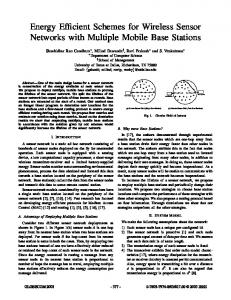
Figure 1: Total path loss in the THz band for transmission distance d of 0.001 m, 0.01 m, 0.1 m and 1 m (“USA Model, Mean Latitude, Summer, H=0”)
mance [8, 17]. The proposed forwarding scheme is thus designed to overcome both the THz frequency selective feature and the multi-hop influence on network performance. The rest of the paper is organized as follows. The background knowledge of EM-WNSNs and the related work on existing forwarding schemes for traditional Wireless Sensor Networks (WSNs) are reviewed in Section 2. The design of the channel-aware forwarding scheme and the end-to-end performance metrics are presented in Section 3. Numerical results of the end-to-end performance evaluation are shown and analyzed in Section 4. Conclusions are in Section 5.
BACKGROUND AND RELATED WORK
In this section, the background knowledge of the THz channel modelling for EM-WNSNs and the work related to existing forwarding schemes in both traditional WSNs and nanonetworks are discussed.
2.1
Pecularities of the THz channel
In the THz band, the total path loss AT is the product of the spread path loss AS and the molecular absorption loss Aabs [10]. The path loss is a function of the transmission distance d and the frequency f and is expressed as: � AT (f, d) = AS (f, d) · Aabs (f, d) =
4πdf c
�2
· ek(f )d
B log2 (1 + SN R(fi , d))
(2)
i=1
Frequency (THz)
2.
n X
(1)
where c is the speed of light 3 · 108 m/s, and k(f ) is the molecular absorption coefficient obtained from the HITRAN (HIgh resolution TRANsmission) molecular absorption database [4]. The total path loss AT as a function of THz frequency are shown in Fig. 1. From Fig. 1 it can be seen that the frequency selective feature is dominant for transmission involving longer distances d. The noise in the THz band is mainly primarily due to molecular absorption noise Nabs . The power spectral density � � (P.S.D.) of Nabs is given by Nabs (f, d) = kB T0 1 − e−k(f )d , where kB is the Boltzmann constant and T0 is the reference temperature 296K. It is shown in [10] that the THz channel capacity can be expressed as a summation of the capacity of each narrow sub-channel, and the capacity of each narrow sub-channel is given by Shannon’s channel capacity. This is achieved by dividing the THz band into n sub-channels, and the THz
S(f ) AT (f, d)Nabs (f, d)
(3)
where n is the number of sub-channels, fi is the centre frequency of the i-th sub-channel, S(f ) is the P.S.D. of the transmitted signal, and B is the bandwidth of each subchannel.
2.2
Forwarding in WSN
A significant amount of research on routing and forwarding techniques for traditional WSNs started more than a decade ago [3]. A recent survey on WSNs [14] and the references contained therein show that new applications for WSNs are constantly emerging providing motivation for more research. To date, most rudimentary WSN data forwarding/relaying schemes are distance related. E.g., in the nearest forwarding scheme, the relay node that is nearest to the sender will be selected as the next hop. Conversely, the longest forwarding scheme chooses the farthest relay node within the transmission range as the next hop. For the random forwarding scheme, the sender randomly selects a relay node within its transmission range to forward data. To improve robustness of WSNs, the routing algorithm proposed in [7] is premised on the knowledge that the robustness is related to the maximum load of any sensor in the network, the transmission range and the energy consumption. Using correlation analysis, the robust geographic routing algorithm that equally distributes the load among the forwarding nodes is found to perform close to the optimal robust algorithm. In comparison with other schemes, the robust geographic routing algorithm not only presents strong robustness but also shows good scalability. Another distance-based scheme, referred to as constrained shortest-path energy-aware scheme [15], restricts the maximum transmission range between 100 m and 900 m, to minimize the energy consumption while maintaining good endto-end delay and throughput performance. A constraint value that balances all the performance metrics is provided without applying any optimization approaches.
2.3
Forwarding in EM-WNSN
In EM-WNSNs, there are two primary physical layer communication technologies, namely molecular communications and EM communications [2]. While WNSNs using molecular communications has been actively researched on, until recently, there is very limited work on forwarding schemes for EM-WNSNs. For nanonetworks, research on data forwarding is in progress and there is insufficient research to support claims of efficacy by adopting classic WSN forwarding schemes. While opportunistic routing has been applied in nanonetworks based on molecular communications [11, 5], there is on-going debate on how the complexity can be extrapolated in practice. For EM-WNSNs, existing studies with data forwarding techniques were primarily concerned with energy conservation.
In [12], a centralized forwarding scheme based on the multihop decision algorithm is proposed. The choice between the single-hop transmission and the multi-hop transmission is determined based on the evaluation of energy saving probability via two parameters, namely the Critical Neighbourhood Range (CNR) and the Required Transmission Power (RTP). For varying distance between the sender and the sink, the multi-hop scheme obtains better performance. Nevertheless, the maximum hop count of the multi-hop scheme is constrained to two which immediately motivates the need to extend the performance evaluation to consider greater number of hops. Addressing the pressing issue of energy consumption, two energy-oriented forwarding schemes, namely, greedy energyharvesting aware and optimal energy-harvesting aware, are proposed for nano-sensors moving uniformly in an environment mimicking human blood vessels [13]. The greedy energyharvesting scheme simply selects the neighbour with the highest energy level to be the relay. Comparatively, the optimal energy-harvesting scheme selects the node that can maximize the network energy level to be the relay. These two schemes show good performance compared with the simple flooding scheme however the optimal scheme requires high computational capacity.
2.4
Our focus and contribution
Most of the forwarding schemes for WSNs do not consider the nano-scale characteristics of EM-WNSNs. Compared to molecular communications, EM-based WNSNs received relatively lesser attention. In view of this, we apply fundamental data forwarding approaches in WSN as starting points for designing forwarding schemes for EM-WNSNs. Unlike the forwarding schemes mentioned above, the novel channel-aware forwarding scheme proposed in this paper is the first to incorporate the peculiarities of THz band in making forwarding decision to match the operating conditions of EM-WNSNs.
3.
DESIGN AND MODELLING
In this section, the design of the channel-aware forwarding scheme proposed for EM-WNSNs is presented. We first state the assumptions and describe the typical deployment scenario. Finally, two metrics: (i) the end-to-end capacity and (ii) the end-to-end delay, are presented to compare the performance of our proposed channel-aware forwarding scheme with traditional WSN forwarding schemes. We rely on four simplifying assumptions to design a forwarding scheme for nanonetworks. (i) The locations of nanosensors are known by the nano sink. (ii) The nano sink is responsible for the centralized operations, e.g. determining the potential relay nodes of the sender when the sender intends to transmit. (iii) All the nanosensors have sufficient energy to relay data. (iv) It is assumed that there is no contention or collision and hence no retransmissions, which is a reasonable assumption with TS-OOK [9].
3.1
Channel-aware Forwarding
A channel-aware forwarding scheme is designed to make sure the data will not be forwarded to the relay node located: (i) in the long-distance region that is adversely affected by
the frequency selective feature and (ii) in the short-distance region that will result in an unnecessarily large hop count. For the node attempting to transmit, all the relay nodes within its transmission range are allocated with a distancebased selection index IS in Eqn. (4) by the nano-sink with sufficient energy and computation capacity, after which the relay node with the highest IS will be chosen as the next-hop relay. The selection index is given by: IS = IP ri − IP en ,
(4)
whereby � IP ri = 10 log10
CT Hz CRef
� , IP en = √
1 d+w
(5)
where d is the distance (in meters), w is the tuning factor of penalty index subject to {w : 0 ≤ w ≤ 1}, CT Hz is the THz channel capacity given by (2), and CRef is the reference channel capacity (neglecting molecular absorption) given by: CRef (d) =
n X
B log2 (1 + SN RRef (fi , d))
(6)
i=1
SN RRef (f, d) =
S(f ) Aspread (f, d)N0
(7)
where fi is the center frequency of the i-th sub-channel, B is the bandwidth of each sub-channel, and N0 is the minimum value of Nabs over the frequency band representing the constant noise P.S.D for the bandwidth B. The index IS is designed to penalise selecting distant nodes since that would result in higher path loss while IP en is designed to avoid the large hop count for repeatedly choosing short-distance transmission. The nearer the relay node is located, the larger the value of IP en will be, which leads to the decrease of IS . It is tuneable via changing the value of w. Due to the distance-dependent frequency selective losses of the THz band, the farther the relay node is located, the more the THz channel capacity CT Hz will decrease than the reference channel capacity CRef . Therefore, the value of CT Hz ) decreases leading to the decrease of IS . ( CRef
3.2
End-to-end Performance Modelling
Due to interference, the channel capacity experiences a certain amount of loss at each hop towards the sink [8, 17]. A simple end-to-end capacity model Ce2e in Eqn. (8) is proposed to measure the reduced capacity due to losses incurred at each hop en-route to the sink. In this model, the impact of interference on the per-hop capacity loss is is a function of the average P relative distance dAV G between adjacent nodes N given by N1 i=1 di , with di denoting the distance between the sender and receiver nodes of the i-th hop. Specifically, if dAV G is short, which means a dense network, the overall interference from other nodes at each hop is high. Conversely, in a network with low node density (large dAV G value), the overall interference at each hop is low. The end-to-end capacity is expressed as: Ce2e = CI (1 − FAV G )N ,
(8)
where CI is the channel capacity contributed by the first hop, N is the hop count determined by the forwarding scheme
random characteristics given by both the random forwarding scheme and the random node placement change are presented with 95% confidence intervals.
(a) Uniform node placement
(b) Random node placement Figure 2: Topology of a string network with 10 relay nodes: (a) uniformly placed (b) randomly placed between the source and the sink. The red node (on the leftmost) represents the source node. The blue node (on the rightmost) represents the sink node. The grey nodes represent the relay nodes. and FAV G is the average capacity loss factor per hop. The value of FAV G is calculated as follows: � � do − dAV G , (9) FAV G = F do where F is the capacity loss factor and do is a constant denoting the reference distance from source-to-sink. The end-to-end delay Te2e is modelled assuming the absence of collision and channel contention and is indicative of the delay incurred with different forwarding schemes, as follows:
o Te2e = N Tdata + Tprop
� N � X di i=1
d0
(10)
o where Tdata is the packet transmission time, Tprop is the source-to-sink propagation delay, di is the i-th hop distance, and N is the total hop count. The first term in Eqn. (10) expresses the processing delay at each of the N hops while the second term expresses the propagation delay.
4.
NUMERICAL RESULTS
In this section, the end-to-end performance of the forwarding schemes is evaluated and analyzed. Results in the figures are evaluated at discrete points with connecting lines to improve presentation.
4.1
Simulation Setup
A 1-m-long string network shown in Fig. 2 is used for the performance evaluation. The number of relay nodes varies from 5 to 50 with a step of 5 to form networks with different node densities. Relay nodes are firstly uniformly placed and then randomly placed between the source and the sink. All the nodes are assumed to be within the transmission range of one another and have enough energy to perform the packet forwarding. For this network the longest distance between two nodes is 1 m. As in [6], the 100-fs-long Gaussian pulse with 0.1 aJ energy is transmitted over the entire THz band (0.1 THz — 10 THz). A packet consisting of 200 bits is transmitted from the source to the sink. The reference capacity loss factor F in Eqn. (9) is set to 0.4 while the tuning factor w in Eqn. (5) is set to 1.2 × 10⁻² . For each number of relay nodes from 5 to 50 with a step of 5, the simulation is repeated 200 times. Each iteration accounts for a different set of forwarding decisions of the random forwarding scheme, and a different topology of the network with randomly placed relay nodes. The results with
For the performance comparison, firstly, the end-to-end performance is evaluated over different node densities (given by number of relay nodes) in channels with fixed water vapour content. The second set of simulations evaluate the end-toend performance as a function of increasing water vapour content.
4.2
Performance Evaluation and Analysis
In this section, the proposed channel-aware forwarding scheme is compared against the four classic forwarding schemes on the basis of the metrics established earlier in Section 3.2.
4.2.1
Varying node densities
For a channel containing 10% H2 O, the end-to-end capacity and delay of forwarding schemes are presented over an increasing number of relay nodes in Fig. 3 and Fig. 4 for the uniform/random node placement respectively. The proposed channel-aware forwarding scheme shows the highest end-to-end capacity and avoids huge end-to-end delay, thus meeting the goal of the design. The proposed scheme makes forwarding decisions based on IS therefore the forwarders selected are mostly close to the ideal relay located at a distance that generates an IS of 1. This decision balances hop count and capacity, which makes the per-hop forwarding distance relatively deterministic. The denser the network is, the more likely a relay node appears on the ideal distance, leading to a more deterministic per-hop forwarding distance. As a result, the end-to-end performance of the proposed scheme tends to be stable with increasing node density. The simplest scheme, which is the single-hop transmission, shows the best delay performance but the channel capacity is restricted by the frequency selective effect. Multi-hop forwarding schemes show better capacity performance than the single-hop transmission in low-density networks but tradeoff delay for this improvement. Comparatively, the proposed scheme shows desirable capacity performance while maintaining low delay even in high-density networks. Compared with the single-hop transmission, the proposed scheme increases the end-to-end capacity by 1379.27%/1221.21% and introduces 0.018%/0.016% extra end-to-end delay for the uniform/random node placement. The longest forwarding scheme have similar performance as single-hop transmission. The longest forwarding scheme only experiences two hops to reach the sink hence the end-toend delay is low. However, the long transmission distance of the first hop penalizes the capacity. As the node density increases, the first-hop transmission distance tends to be longer, meanwhile, the per-hop capacity loss gets larger, therefore the end-to-end capacity of the longest scheme gradually gets inferior to that of the single-hop transmission. The nearest forwarding scheme is highly dependent of the node density of the network. It exhibits high end-to-end capacity only when the node density is low (e.g. the network with 5, 10 and 15 relay nodes) contributed by two factors: (i) the short distance transmission that indicates high capacity and (ii) relatively small hop count. When the node density increases, the benefit of shorter transmission distance
10
4
10
2
Proposed Scheme Nearest Scheme Random Scheme Longest Scheme Single Hop
100 10-2
End-to-end Delay (ns)
End-to-end Capacity (bit/s)
668
106
5
10
15
20
25
30
35
Number of Relay Nodes
40
45
667.5
667
666.5 5
50
Proposed Scheme Nearest Scheme Random Scheme Longest Scheme Single Hop
10
15
(a) End-to-end capacity
20
25
30
35
Number of Relay Nodes
40
45
50
(b) End-to-end delay
668
108 10
End-to-end Delay (ns)
End-to-end Capacity (bit/s)
Figure 3: End-to-end performance for uniform node placement in the channel with 10% H2 O
6
104 102
Proposed Scheme Nearest Scheme Random Scheme Longest Scheme Single Hop
100 10-2
5
10
15
20
25
30
35
Number of Relay Nodes
40
45
667.5
667
666.5 5
50
Proposed Scheme Nearest Scheme Random Scheme Longest Scheme Single Hop
10
15
(a) End-to-end capacity
20
25
30
35
Number of Relay Nodes
40
45
50
(b) End-to-end delay
667.3
107
Proposed Scheme Nearest Scheme Random Scheme Longest Scheme Single Hop
106
105
104
1
10
20
H O (%)
30
40
End-to-end Delay (ns)
End-to-end Capacity (bit/s)
Figure 4: End-to-end performance for random node placement in the channel with 10% H2 O
667.1 667 666.9 666.8 666.7 666.6 1
50
Proposed Scheme Nearest Scheme Random Scheme Longest Scheme Single Hop
667.2
10
20
2
H O (%)
30
40
50
2
(a) End-to-end capacity
(b) End-to-end delay
107
Proposed Scheme Nearest Scheme Random Scheme Longest Scheme Single Hop
106
105
104
1
10
20
H2O (%)
30
40
50
(a) End-to-end capacity
End-to-end Delay for (ns)
End-to-end Capacity (bit/s)
Figure 5: End-to-end performance for uniform node placement in the channel with 1%—50% H2 O 667.3
Proposed Scheme Nearest Scheme Random Scheme Longest Scheme Single Hop
667.2 667.1 667 666.9 666.8 666.7 666.6 1
10
20
H2O (%)
30
40
50
(b) End-to-end delay
Figure 6: End-to-end performance for random node placement in the channel with 1%—50% H2 O no longer offsets the detriment attributed to the larger hop count and the larger per-hop capacity loss given by Eqn. (9). Therefore, the end-to-end performance of capacity and delay both tend to be worse with increasing node density.
The random scheme selects different combinations of forwarding nodes. Results for the random scheme are presented as an average of 200 iterations. It is observed that the random scheme records higher hop count compared to our pro-
posed scheme. This is because the denser the network is, the higher the expectation of residual hops would be, leading to higher end-to-end delay. Moreover, the end-to-end capacity and delay curves are sandwiched approximately between the nearest scheme and the longest scheme. This is due to the fact that the probability of consistently selecting the nearest node or the farthest node is low. Thus, it has a smaller hop count than the nearest scheme and higher per-hop capacity than the longest scheme.
4.2.2 Varying H2 O percentage The results of averaged end-to-end performance over an increasing percentage of H2 O are shown in Fig. 5 and Fig. 6 for the uniform/random node placement respectively. Overall, the end-to-end capacity of all schemes decrease when the channel has higher H2 O content. For most schemes, the end-to-end delay is propotional to the hop count determined by specific forwarding schemes and is not directly influenced by the H2 O content. However, this must be interpreted with the assumption that no collisions or retransmissions occur. In terms of the end-to-end capacity, all the multi-hop forwarding schemes except the longest scheme outperform the single-hop transmission which is strongly affected by the frequency selective feature. Our proposed scheme shows the best end-to-end capacity performance with slightly decreased end-to-end delay over the increasing amount of H2 O. It can be inferred that the end-to-end delay serves as a tradeoff for the end-to-end capacity. Different forwarding schemes take advantage of this tradeoff in different levels based on their forwarding mechanisms.
5.
CONCLUSIONS
In this paper, classic multi-hop forwarding schemes and singlehop end-to-end transmission are applied in EM-WNSNs. A novel channel-aware forwarding scheme, which provides a solution to the THz frequency selective feature from the perspective of networking, is proposed for EM-WNSNs. The proposed forwarding scheme is designed to achieve high channel capacity meanwhile avoiding large hop counts. Focusing on the end-to-end performance, end-to-end capacity and end-to-end delay are the selected metrics for evaluating the performance of all the forwarding schemes. In comparison with other schemes, the results show that the proposed channel-aware forwarding scheme ensures high end-to-end capacity while maintaining acceptable end-to-end delay for networks with different node densities and channel environments containing different percentages of H2 O.
6.
REFERENCES
[1] A. Afsharinejad, A. Davy, B. Jennings, and S. Balasubramaniam. GA-based frequency selection strategies for graphene-based nano-communication networks. In Proceedings of ICC, pages 3642–3647, Sydney, Australia, 10-14 June 2014. [2] I. Akyildiz and J. Jornet. The internet of nano-things. IEEE Wireless Communications, 17(6):58–63, December 2010. [3] J. N. Al-Karaki and A. E. Kamal. Routing Techniques in Wireless Sensor Networks: A Survey. IEEE Wireless Communications, 11(6):6–28, Dec 2004.
[4] Y. L. Babikov, I. E. Gordon, S. N. Mikhailenko, L. S. Rothman, and S. A. Tashkun. HITRAN on the Web – a new tool for HITRAN spectroscopic data manipulation. In Proceedings of the 12th International HITRAN Conference, 29-31 August 2012. [5] S. Balasubramaniam and P. Lio. Multi-hop conjugation based bacteria nanonetworks. IEEE Transactions on NanoBioscience, 12(1):47–59, 2013. [6] P. Boronin, V. Petrov, D. Moltchanov, Y. Koucheryavy, and J. M. Jornet. Capacity and throughput analysis of nanoscale machine communication through transparency windows in the terahertz band. Nano Communication Networks, 5(3):72–82, 2014. [7] Z. A. Eu and W. K. G. Seah. Impact of transmission power and routing algorithms in designing robust wireless sensor networks. In PIMRC, pages 1–5. IEEE, 2007. [8] Y. Gao, D.-M. Chiu, and J. C. Lui. Determining the End-to-end Throughput Capacity in Multi-hop Networks: Methodology and Applications. In SIGMETRICS, pages 39–50, Saint Malo, France, 2006. [9] J. Jornet and I. Akyildiz. Femtosecond-long pulse-based modulation for terahertz band communication in nanonetworks. 2014. [10] J. M. Jornet and I. F. Akyildiz. Channel Modeling and Capacity Analysis for Electromagnetic Wireless Nanonetworks in the Terahertz Band. IEEE Transactions on Wireless Communications, 10(10):3211–3221, October 2011. [11] P. Lio and S. Balasubramaniam. Opportunistic routing through conjugation in bacteria communication nanonetwork. Nano Communication Networks, 3(1):36–45, 2012. [12] M. Pierobon, J. M. Jornet, N. Akkari, S. Almasri, and I. F. Akyildiz. A routing framework for energy harvesting wireless nanosensor networks in the terahertz band. Wireless Networks, pages 1–15, 2014. [13] G. Piro, G. Boggia, and L. A. Grieco. On the design of an energy-harvesting protocol stack for body area nano-networks. Nano Communication Networks, 2014. [14] P. Rawat, K. Singh, H. Chaouchi, and J. Bonnin. Wireless sensor networks: a survey on recent developments and potential synergies. The Journal of Supercomputing, 68(1):1–48, 2014. [15] M. Youssef, M. Younis, and K. Arisha. A constrained shortest-path energy-aware routing algorithm for wireless sensor networks. In Proceedings of the IEEE WCNC, pages 794–799, Orlando, FL, USA, 17-21 Mar 2002. [16] E. Zarepour, M. Hassan, C. T. Chou, and A. Adesina. Frequency hopping strategies for improving terahertz sensor network performance over composition varying channels. In Proceedings of the IEEE WoWMoM, pages 1–9, Sydney, 16-19 June 2014. [17] H. Zhao, E. Garcia-Palacios, A. Song, and J. Wei. Calculating end-to-end throughput capacity in wireless networks with consideration of hidden nodes and multi-rate terminals. In VTC, pages 1–5. IEEE, 2011.