Hindawi Wireless Communications and Mobile Computing Volume 2018, Article ID 2139794, 12 pages https://doi.org/10.1155/2018/2139794
Research Article FPGA Implementation of UFMC Based Baseband Transmitter: Case Study for LTE 10MHz Channelization Atif Raza Jafri ,1 Javaria Majid,1 Lei Zhang,2 Muhammad Ali Imran ,2 and M. Najam-ul-Islam1 1
Electrical Engineering Department, Bahria University, Islamabad, Pakistan School of Engineering, University of Glasgow, Scotland, UK
2
Correspondence should be addressed to Muhammad Ali Imran;
[email protected] Received 18 March 2018; Revised 28 April 2018; Accepted 4 June 2018; Published 10 July 2018 Academic Editor: Maode Ma Copyright © 2018 Atif Raza Jafri et al. This is an open access article distributed under the Creative Commons Attribution License, which permits unrestricted use, distribution, and reproduction in any medium, provided the original work is properly cited. Universal filtered multicarrier (UFMC) is a low complexity promising waveform that provides quasi-orthogonal property among subcarriers. In addition, it can achieve much better out-of-band emission performance than orthogonal frequency division multiplexing (OFDM) system. Authors have proposed a hardware platform to implement a UFMC transmitter in this paper. Highly reduced complexity schemes for IFFT, filtering, and spectrum shifting are realized on actual hardware. This helps to achieve overall architecture of the transmitter at the cost of minimal FPGA resource usage. Hence, the overall design uses only 1038 slice registers, 1154 slice LUTs, and 64 multipliers of Xilinx Virtex-7 XC7VX330t device. A throughput of 773.5 Msamples/sec at an operational frequency of 364 MHz is achieved. This throughput is adequate for processing 50 Physical Resource Blocks (PRB) of LTE 10 MHz channelization in required time. The presented architecture provides a latency of only 2% of one LTE 10MHz channelization symbol due to the implementation of pipelining at different levels. Although the presented hardware design in its current form meets LTE 10MHz channelization throughput requirements, further increase in throughput is possible due to the scalable nature of the architecture. To the best of our knowledge, this work is first ever FPGA solution for UFMC transmitter presented in the literature.
1. Introduction ADVENT of 5G mobile telecommunication technology has sparked the start of new era of research in the field of telecommunications. 5G standardization aims to address requirements related to three main communication scenarios: enhanced mobile broadband (eMBB), massive machine type communications (mMTC), and ultrareliable low latency communications (URLLC) [1, 2]. To achieve such challenging performance requirements, numerous waveforms have been proposed [3, 4], which include cyclic prefixorthogonal frequency division multiplexing (CP-OFDM), filter bank multicarrier (FBMC) [5, 6], generalized frequency division multiplexing (GFDM) [7], universal filtered multicarrier (UFMC) [8], filtered OFDM (FOFDM) [9], windowed OFDM (WOLA-OFDM) [10], and their variants [11, 12]. Among these waveforms, UFMC is a promising choice as per subband filtering which is performed to trade
off the out-of-band emission and complexity performance. When comparing with FBMC, UFMC is better in case of short packet length [13] and has only slightly worth out-ofband emission for large packet size [9, 14]. In addition, it has much better compatibility to multiantenna system than FBMC system. In addition, as a subband filtered multicarrier (SFMC) system, UFMC is flexible to support multiservice radio access network (RAN) slicing in physical layer [15, 16]. For example, based on UFMC, [17] proposes a comprehensive framework for multiservice system to support multiple types of services/slices in both generalized and nongeneralized synchronized systems. This aspect addresses the flexibility requirement perspective of 5G. Apart from performance, hardware complexity is another key factor associated with acceptability of any proposed waveform. In this regard, a reduced complexity UFMC transmitter architecture is proposed in [18] that uses frequency domain approach for generating UFMC waveform. Such simplified
2
Wireless Communications and Mobile Computing
idea is also mentioned in [9] to reduce the implementation complexity of the algorithm. The main idea behind is application of filters on each PRB in frequency domain and then converting it back to time domain using IFFT. If classical scheme of UFMC transmitter [8] has complexity of 150 times that of CP-OFDM, the frequency domain UFMC implementation has complexity equals 120 times. Another scheme to reduce UFMC transmitter complexity is presented by Knopp et al. in [19]. This modified approach reduces complexity to around 25 times of CP-OFDM by reducing size of IFFT and then implementing upsampling, filtering, and spectrum shifting. Further reduction of this model is proposed in [20] which will be used as baseline in this paper. However, the complexity reduction claims of above stated UFMC schemes are based on counting the arithmetic operations involved but not on actual hardware implementation. This is due to the unavailability of actual hardware implementation results for UFMC. On the other hand, actual FPGA implementation results are available for FBMC transmitter in the work of Nadal et al. [21] and Robin et al. [22]. In this paper, we have filled this gap of unavailability of actual hardware implementation of a UFMC transmitter. Hence, first real time FPGA implementation of UFMC transmitter complying with the timing requirements of 10MHz channelization of LTE is presented here. To achieve this real time hardware, the following is the summary of contributions: (i) Proposal of reduced complexity implementation solutions for all constituent building blocks of the transmitter while avoiding computation/storage of redundant information (ii) Hardware design of the constituent building blocks while achieving highest possible operational frequency at low area overhead (iii) Resource allocation to constituent blocks and their scheduling in order to meet the established timing requirements for LTE 10MHz channelization (iv) Finally, UFMC FPGA implementation results comparison to OFDM transmitter implementation results. The rest of the paper is organized as follows: the next section presents the system model. Section 3 is dedicated to architectural choices for our transmitter implementation. Design of transmitter is discussed in Section 4. In Section 5, implementation and performance results are tabulated to compare with the state of the art. Finally, Section 6 concludes the paper.
2. System Model UFMC is filtered variant of zero padding based OFDM (ZPOFDM). The symbols obtained from mapper are divided into groups of carriers. These groups of carriers, i.e., PRBs, go through the process of IFFT and filtering after which they are summed up to generate the final UFMC waveform. UFMC model shown in Figure 1 as proposed in [8] is the basic UFMC model. On the other hand, a low complexity UFMC
0
Zero Padding & IDFT
0
1
Zero Padding & IDFT
1
"−1
N−1
Band Pass Filter (PRB 0)
∑ x0(k) ℎ0 (u − k)
k=0
N−1
Band Pass Filter (PRB 1)
Zero B−1 Band Pass Padding & Filter (PRB IDFT B-1)
∑ x1(k) ℎ1 (u − k)
k=0
z(u)
N−1
∑ xB−1(k) ℎB−1 (u − k)
k=0
Figure 1: Classical UFMC transmitter scheme.
transmitter model proposed in [19] is shown in Figure 2. Both implementations are explained below in detail. 2.1. Classical UFMC Transmitter. As shown in Figure 1, the input to this classical scheme is a set of constellation mapped symbols. These symbols are divided into number of PRBs in LTE standard. Each of these PRBs contain 𝑚 = 12 data carriers in LTE. Let 𝐵 be the number of PRBs. Each of these PRBs is zero padded to make a stream of N symbols. Each stream undergoes N-point IFFT which is then passed through Dolph-Chebyshev FIR filter. At the end, all streams are added up to form final UFMC waveform. UFMC waveform is expressed using following equation [20]: 𝐵−1 𝑁−1
𝑧 (𝑢) = ∑ ∑ 𝑥𝑖 (𝑚) ℎ𝑖 (𝑢 − 𝑚)
(1)
𝑖=0 𝑚=0
where 𝑢 = 0, 1, . . . , 𝑁 + 𝐿 − 1 and 𝐿 is the filter length. In case of transforming an OFDM based waveform into UFMC waveform with the same system overhead in time domain, filter length will be equal to 𝐿 = 𝐿 𝐶𝑃 -1 where 𝐿 𝐶𝑃 is the cyclic prefix length. For 10MHz channelization of LTE, there are 600 data carriers which are divided into 50 PRBs and 𝑁 = 1024 (𝑁 = 0, 1, . . . , 1023). Filter length depends on long or short cyclic prefix of LTE and hence value varies from 73 to 80 taps [19]. 2.2. Modified UFMC Transmitter. Unlike the classic model, the modified UFMC model proposed in [19] uses smaller IFFT size, i.e., 𝑁 . Moreover, 𝑚 subcarriers of each PRB are placed on same initial positions as that of first PRB subcarriers positions. Each data block is then zero padded with 𝑁 −𝑚 zeros. 𝑁 -IFFT instead of 𝑁-IFFT is applied [19]. The time domain data is then upsampled by the factor of 𝑁/𝑁 . The upsampled data from each PRB stream is passed through same low pass filter to remove out-of-band emissions. Each PRB related data is then shifted to its allocated frequency position. Finally data related to all PRBs is added to form final UFMC waveform. This scheme provides complexity reduction through reducing the size of IFFT and avoiding multiplication with zero during filtering of upsampled data. The expression for overall complexity for this scheme of implementation in terms of arithmetic operations is given
Wireless Communications and Mobile Computing
Input Data
3
Zero Padding & IDFT
Low Pass Filter
Freq. Shift to PRB 0
Zero Padding & IDFT
Low Pass Filter
Freq. Shift to PRB 1
Zero Padding & IDFT
Low Pass Filter
Freq. Shift to PRB B-1
UFMC OUT
Figure 2: Low complexity UFMC scheme.
in [19]. Using this expression, the complexity of UFMC transmitter is almost 23.5 times as compared to CP-OFDM scheme for 10MHz channelization. Hence, as compared to classical UFMC scheme of Figure 1 that has 150 times complexity of CP-OFDM, more than 6 times complexity is reduced.
X(0) X(32) X(16) X(48) X(8) X(40) X(24)
3. Architectural Choices
X(56)
We have taken the simplest model of UFMC proposed in [19] as baseline for our work. For scheme in [19], reduced complexity solution for IFFT, filtering, and spectrum shifting are proposed in [20]. These simplifications are discussed briefly below whereas their actual hardware implementation with timing constraints is presented later in this paper.
X(36)
X(4) X(20) X(52) X(12) X(44) X(28) X(60)
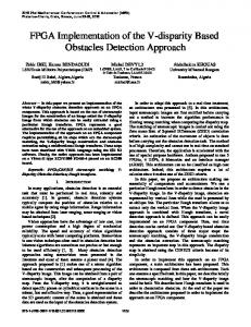
3.1. IFFT. To obtain low computational complexity in IFFT, Radix-2 algorithm is selected as there are opportunities to avoid redundant computation in case of UFMC implementation through UFMC transmission scheme of Figure 2. Consider the portion of Radix-2 decimation in time (DIT) with bit reversed input format implementation of 64point IFFT as show in Figure 3. In first stage, only upper inputs of used butterflies (BF) have nonzero value, i.e., values from 12 subcarriers of a PRB, whereas the second inputs are zero. Hence, the portion of data path shown as bold lines in Figure 3 needs computations. Since the multiplication with twiddle factor is present in lower path, shown as dotted lines, no multiplication is required. Hence, the input value will appear on both outputs without any processing. It is, therefore, the computations in first stage that are not required. Same is the case with the second stage. In third stage, only half of the BFs will be executed as shown in Figure 3. In subsequent stages all BFs will be fully used. Hence, out of 192 BFs only 112 BFs will be computed. As the computation of one Radix-2 BF needs 4 real multiplications (RM) and 6 real additions/subtractions (RA/S), the overall complexity of 112 BF will be 448 RM and 672 RA/S. In order to exploit this simplification, one needs to copy 12 pieces of data at multiple locations before starting the computation of useful butterflies, e.g., first sample of PRB; i.e., X(0) shall be copied at locations 32, 16, and 48 of input
Figure 3: Part of Radix-2 implementation of 64-point IFFT.
memory of third stage of butterflies as shown in Figure 3. In the same way 12 carriers will be copied at required locations. To implement 64-point IFFT, Radix-4 architecture is also considered. The partial data flow of 64-point IFFT using Radix-4 implementation is shown in Figure 4. In total there are 48 butterflies, i.e., 3 stages with each stage having 16 butterflies. The first-stage BF computations are redundant as only first input is nonzero which appears on all 4 outputs of each BF (shown as solid line). In the second stage, the last inputs of all 16 BF (shown as dotted lines) are zero; this removes the use of 1 complex multiplication and 4 complex additions in each butterfly of second stage. Finally, in third stage all inputs are fully utilized. Placement of hardware for one complete Radix-4 BF, i.e., hardware comprised of 3 complex multipliers and 12 complex adders/subtractors, will be fully utilized in third stage; however, for second stage BFs computation of one complex multiplier and 4 complex adders will not be utilized. On the other hand, if resources in shape of one complex multiplication and one complex addition/subtraction (as used in Radix-2 BF hardware architecture) are provided to
4
Wireless Communications and Mobile Computing
X(0) X(16) X(32) X(48) X(4) X(20) X(36) X(52) X(8) X(24) X(40) X(56) X(12) X(28) X(44) X(60)
1 2 3 2 4 6 3 6 9
Figure 4: Part of Radix-4 implementation of 64-point IFFT.
compute Radix-4 BFs, additional hardware for control signal generation and registers to store intermediate results will be required. Moreover, there will a penalty of extra clock cycles while performing read/write operations on intermediate data during Radix-4 BF computation. This will slow down the whole process. While comparing the utilization of Radix-2 and Radix4 implementation schemes for simplified IFFT computation, Radix-2 has a clear advantage over Radix-4 scheme in terms of lesser hardware placement, 100 % utilization rate of placed hardware, and simplification of the implementation. In addition, Radix-2 solution encourages the scalable architecture where more Radix-2 BFs can be placed in parallel to achieve higher throughput. Hence, placement of fewer hardware resources, higher utilization rate of placed hardware, less complexity of architecture, and support for scalability are the key elements for selecting Radix-2 implementation in order to exploit the simplified solution of computing a 64-point IFFT operation during UFMC waveform synthesis. 3.2. Filtering. As shown in Figure 2, upsampling by a factor of 𝑁/𝑁 is performed by insertion of zeros between each output sample 𝑥𝑖 (𝑚) of IFFT. However, multiplication of only nonzero samples with filter coefficients is useful. The scenario of upsampling with a factor of 16 is shown in Figure 5. Here, out of sixteen, only one element is nonzero which is multiplied with filtering coefficients. Hence, multiplier for zero element is not required. Moreover, during the computation of different filter outputs, one nonzero value 𝑥𝑖 (𝑚) is multiplied with different filtering coefficients ℎ𝑙 . Hence, we can multiplex the filtering coefficients. The circuit diagram shown in Figure 6 implements this idea as given in [23] for poly-phase filter applications. Once a sample enters the filter and shift of memory elements is performed, then in next 16 cycles the filter coefficients are multiplexed one by one to generate 16 outputs of the filter. Hence, for our case study, on one side only 64 samples from IFFT operations will be required; i.e., no actual zero padding is required and secondly only 5 multipliers, 4 shift registers, 4 adders, and 5 16-to-1 multiplexers will be
used in place of 73 to 80 multipliers and 72 to 79 adders (depending on filter taps) and shift registers. Moreover, the same hardware can be used for considered tap lengths of 73 or 80 by changing the values of filter coefficients at the input of multiplexers. 3.3. Spectrum Shifting. In the scheme of [19], the filtered data of each PRB except first one is shifted to its original spectrum. For this, each filtered data element is multiplied with a complex spectrum shifting coefficient which is computed as 𝑒−𝑗2𝜋(𝑚×𝑖)𝑛/𝑁 = cos (
2𝜋 (𝑚 × 𝑖) 𝑛 ) 𝑁
2𝜋 (𝑚 × 𝑖) 𝑛 − 𝑗 sin ( ) 𝑁
(2)
In order to elaborate the idea, consider the case where 𝑚 = 12, 𝑁 = 1024, 𝑛 is filtered data sample number ranging from 0 to 1095, i.e., total of 1096 elements. Finally, 𝑖 represents PRB number. Hence, for 50 PRBs, 49 sets of filtering coefficients are required. While keeping 16 bits for each real and imaginary component of one filtering coefficient, total memory of 49 × 16 × 2 × 1096 = 1.63 Mbits will be required to store spectrum shifting coefficients in Look-Up Table (LUT) for our case study. On the other hand, if these coefficients are computed on the fly, the processing delay will occur. Hence, in [20] a simpler solution is proposed by simplifying the ratio of 𝑚 and 𝑁 in (2) as under 𝑒(−𝑗2𝜋(12)×(𝑖×𝑛))/1024 = cos (
2𝜋 (3 × 𝑖 × 𝑛)) 256
− 𝑗 sin (
2𝜋 (3 × 𝑖 × 𝑛)) 256
(3)
In expression (3), we need 256 discrete values, i.e., 0 to 255 for complete 2𝜋 circle, and values are repeated beyond it. Thus, if we make a ROM containing 256 sine and cosine values in the step of 2𝜋/256, address generated through (3 × 𝑖 × 𝑛) 𝑚𝑜𝑑𝑢𝑙𝑜 (256) will provide the sine and cosine value for a particular value of 𝑖 and 𝑛 in (2). Moreover, (3 × 𝑖 × 𝑛) 𝑚𝑜𝑑𝑢𝑙𝑜 (256) can be achieved easily by taking 8 least significant bits from the result of 3×𝑖×𝑛. Hence, here we need only 16 × 2 × 256 = 8 Kbits and two multipliers to generate filtering coefficients for 50 PRBs as shown in Figure 7. There is another possibility of reduction in the size of LUT which is shown in Figure 8. Here we store 128 values related to one-half of cosine wave in a dual port ROM. This ROM has two address lines, i.e., Address 1 and Address 2. Address 1 lines are connected with 7 least significant bits (LSbs) of output of %(256) operation whereas the most significant bit (MSb) is connected to a multiplexer MUX-1. The function of MUX1 is to output the value of cos((2𝜋/256)(3 × 𝑖 × 𝑛)). In case the output of %(256) operation is within 0-127 the associated cosine value read from Data 1 lines is transferred to the output; otherwise the 2’s complement of read value (shown as multiplication with -1) is sent to output. In case negative of sine wave is required, which leads cosine by an angle of 𝜋/2, 64 is added in the output of %(256) operation. The 7 LSBs of the result of this addition are connected to Address 2 lines of
Wireless Communications and Mobile Computing
()
Z-1
0 0
Z-1
h0
0 0
h7
0 Z-1
xi (4)
h8
0
xi (4) Z-1
0
Z-1
h9
5 0
0
Z-1
h23
0
xi (3)
xi (3)
h24
Z-1
0
Z-1
h25
0
h39
0 Z-1
xi (2)
h40
0
xi (2)
0
Z-1
Z-1
h41
0
h55
0 Z-1 h56
0
xi (1)
xi (1)
Z-1
0
Z-1
h57
0
0
Z-1
h71
xi (0)
h72
()
Figure 5: FIR filter of classical UFMC.
()
Z-1 h8 0 0 h1
Z-1
Z-1
h24 h9 h10
h40 h25 h26
h56 h41 h42
h72 h57 h58
h23
h39
h55
h71
n
i
Z-1
3
h7
% 256 8-bit Address
64 ()
= 0.0000 -sin( × 1/128) = -0.02454
cos( × 2/128)
-sin( × 2/128)
= 0.99879
= - 0.04906
MSb
Address 0 8-bit Address = (i × × )%256
0
1
cos( × 4/128) cos( × 5/128)
MUX-2
= 1.0000 cos( × 1/128) = 0.9996
10-bit
-sin(2 × × i × n/1024)
18-bit
cos( × 3/128) Data-2
Data-1
cos( × 6/128) -1
cos( × 7/128)
-1
0
1
cos(2 × × i × n/1024)
-sin( × 0/128)
3
cos( × 2/128)
MUX-1
cos( × 0/128)
0th location
cos( × 1/128)
16 bits
7-bit Address-1 (7-LSbs)
cos( × 0/128)
256-Location LUT For Spectrum Shifting Coefficients 16 bits
7-bit Address-2 (7-LSbs)
MSb
Figure 6: Simplified filtering scheme.
-2 (12 × i)n/1024
cos(×125/128) cos(×126/128) cos(×127/128)
cos(×255/128) = 0.99969
-sin(×255/128) = -0.02454
Address 255
Figure 7: LUT based solution for storing frequency shifting coefficients in 256-location ROM for LTE 10 MHz channelization specifications.
128-location ROM. The data output mechanism to generate sin((2𝜋/256)(3 × 𝑖 × 𝑛)) from MUX-2 is same as described for cosine values. Using this scheme, the LUT size reduces 4 times as compared to scheme presented in Figure 7 at a cost of few combinational logic elements and provision of second port of the ROM. In our implementation, we have used this scheme for spectrum shifting.
127th location
Figure 8: LUT based solution for storing frequency shifting coefficients in 128-location ROM carrying 128 values of one-half of a cosine wave.
4. UFMC Transmitter Design for LTE 10MHz Channelization In order to achieve a hardware design for LTE 10MHz channelization, we need to find the required time to process all PRBs. Based on this information we can scale and schedule hardware resources. 4.1. Timing Requirements. The useful OFDM symbol time is 66.7𝜇sec whereas there are two types of CP lengths. The long CP is 5.2𝜇sec and short one has a duration of 4.7𝜇sec. Keeping in view the worst case timing constraint, we consider
6
Wireless Communications and Mobile Computing
short symbol time, i.e., 71.3𝜇sec, as maximum time to process 50 PRBs to form a UFMC waveform. In order to scale hardware resources, maximum achievable frequency of a hardware architecture must be known. Hence, we separately modeled data path of two-stage pipelined architecture of IFFT butterfly and 3-stage pipelined architecture for Multiply and Accumulate (MAC) operators of FIR filter (detailed in subsequent sections). We then went through place and route process on Virtex-7 FPGA to find the maximum achievable frequency. It was found that the maximum achievable frequency is 364MHz. Based on the available processing time (𝑡) and the frequency (𝑓) at which our hardware can work, following calculation is made to find the number of clock cycles available for UFMC processing:
Idle
Start == 1 T r_adr w_adr
0 0
Processig
T
2LSBs of r_adr == 11
Time of Processing 50 PRBs = 𝑡 = 71.3𝜇𝑠
r_adr
r_adr+1
F T
2LSBs of r_adr == 10
Time of Processing 1 PRB = 𝑡𝑃𝑅𝐵 = 1.426𝜇𝑠
w_adr w_en
w_adr+1 1
F
Maximum Operational Frequency 𝑓 = 364 𝑀𝐻𝑧 Clock cycles for 1 PRB = (1.426 𝜇 𝑠𝑒𝑐) (364𝑀𝐻𝑧)
F
w_adr w_en
w_adr+1 1
3 LSBs of w_adr are all 1
(4)
= 519
F
T 2 LSBs of w_adr are all 1
F
r_adr
r_adr+1
T
Clock cycles for 50 PRB processing = 519 × 50
r_adr
r_adr+1
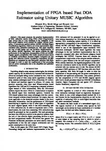
=25, 950 Hence, target is to process single PRB in 519 clock cycles. 4.2. Hardware Architecture of Building Blocks. The UFMC waveform synthesis is performed in 5 processes as shown in Figure 2. In our hardware, to eliminate redundant butterfly computations we have split IFFT process into two processes, namely, data fetching and IFFT computation. The upsampling is not actually performed in hardware due to adopted architecture of filtering. FIR filtering, spectrum shifting, and addition of processed PRBs are the next three processes in our implementation. The details related to hardware for each process are given in subsequent sections. (1) Process 1: Data Fetching. The purpose of this process is to enable the simplified IFFT process by avoiding redundant butterflies. To achieve this, the first task is to copy the 12 nonzero input data, i.e., data related to one PRB from external memory (containing data of all PRBs) at required places in 64-location memory attached to 64-point IFFT process. The read locations of data related to first PRB from external memory and write location in memory attached to IFFT block are arranged in Table 1. In order to perform this data transfer, a Finite State Machine with Data path (FSMD) is designed for which (Algorithmic State Machine) ASM Chart is shown in Figure 9. The FSMD has three states, Idle, Processing, and Done. The system remains in Idle state till the time start signal is asserted and system moves to Processing State. Two registers of 4 bits and 6 bits, one to generate the read address (r adr) for external memory and other to generate write addresses (w adr) for memory of IFFT block, respectively, are created in this FSMD. These registers start from zero value while
r_adr = 14 and w_adr=N-1
F
T Done Process_end = 1
Figure 9: ASM Chart for data fetching process.
entering in Processing State. Since the adopted IFFT process is Radix-2 DIT bit reversed input based, the final addresses for both memories are created by reversing the bits of r adr and w adr registers and shall be denoted by bit reversed r adr and bit reversed w adr in following part of this paper. During the Processing State, the value of r adr goes from 0 to 14 rather than going from 0 to 11. This is because when the value of r adr is either 3, 7, or 11, the address generated for external memory through bit reversed r adr signal is greater than 11 whereas the required data resides in locations from 0 to 11 for first PRB. Hence, when r adr has these values, it is incremented by 1 and no write operation is performed; i.e., w adr is not incremented and write enable signal remains 0. This is shown in the first decision block of Processing State of Figure 9. The second case is when r adr has values equal to 2, 6, 10, and 14. For these values of r adr, 2 LSBs of r adr will be “10” and corresponding bit reversed r adr values will be 4, 6, 5, and 7. Once a data is read from these locations, it will be copied in 8 locations by, first of all, incrementing w adr by 1 and then by generating address of IFFT process RAM through bit reversed w adr, i.e., bit reversal of w adr. For the rest of the r adr registers values, i.e., 0, 1, 4, 5, 8, 9, 12, and 13 the
Wireless Communications and Mobile Computing
7
Table 1: Locations of data copying from external to internal memory. EXTERNAL MEMORY LOCATIONS 0th 1st 2nd 3rd 4th 5th 6th 7th 8th 9th 10th 11th
EXTERNAL MEMORY
Frequency Block No
DATA IN EXTERNAL MEMORY X(0) X(01) X(02) X(03) X(04) X(05) X(06) X(07) X(08) X(09) X(10) X(11)
Twiddle Factors (ROM)
RAM
No of frequencies in single block
write_address
read_address
data_read
INTERNAL MEMORY LOCATIONS 0th, 32nd, 16th, 48th 1st, 33rd, 17th, 49th 2nd, 34th, 18th, 50th 3rd, 35th, 19th, 51st 4th, 36th, 20th, 52nd, 12th, 44th, 28th, 60th 5th, 37th, 21st, 53rd, 13th, 45th, 29th, 61st 6th, 38th, 22nd, 54th, 14th, 46th, 30th, 62nd 7th, 39th, 23rd, 55th, 15th, 47th, 31st, 63rd 8th, 40th, 24th, 56th 9th, 41st, 25th, 57th 10th, 42nd, 26th, 58th 11th, 43rd, 27th, 59th
PROCESS_1
data_write
Write_enable
RAM clk
reset
flag
data_write_1
read_address_3
data_read_3
data_write_2
Figure 10: Block diagram of data fetching process.
read_address_1 read_address_2
bit reversed r adr for external memory will be 0, 8, 2, 10, 1, 9, 3, and 11 and each read data from external memory shall be copied in 4 locations of IFFT process memory through bit reversed w adr. A total of 68 clock cycles are required to complete this process. Hence, 451 clock cycles are left from 519 clock cycles to execute remaining four processes related to one PRB. In order to copy data related to PRBs other than first PRB in IFFT process RAM, the developed mechanism is shown in Figure 10. The overall address to external memory is computed by multiplying the PRB number with 12 and adding the bit reversed address coming from the FSMD of data fetching process. (2) Butterfly Execution. This process takes the data from IFFT process RAM on which data is arranged by data fetching process. In fact this RAM is a true dual port RAM used to take two simultaneous inputs for a butterfly computation. The other memory attached to this process contains twiddle factors. Process of butterfly execution is shown in Figure 11. Using this process, the reduced number of butterflies, i.e., 112 for 𝑚 = 12 and 𝑁 = 64, is computed to take 64-point IFFT of one PRB. As stated earlier, the butterfly hardware is a three-stage pipelined architecture. Hence, three clock cycles are required to perform one butterfly computation;
data_read_1
data_write_1
data_read_2
data_write_2 write_en_1
write_en_1
PROCESS_2
write_en_2
write_en_2 clk
reset
flag
Figure 11: 64-point IFFT process block diagram.
i.e., in first clock cycle address for two inputs is generated. In second cycle, data read and execution of first stage of butterfly are performed whereas in third clock cycle final result of butterfly is computed and written at same location of dual port RAM from where data was fetched. As butterflies’ computation of first two stages is redundant (Figure 3), the computations will start from 3rd stage. Half of the butterflies are computed in 3rd stage and all butterflies in the next 3 stages. To achieve this, two counters are used for reading the data form RAM (Figure 11). Counter 1 starts from ‘000000’ and counter 2 starts from ‘000001’ binary values. During execution of 3rd stage of butterflies, the address for 2 inputs of butterfly computation will be generated in a way that four LSBs of both counters will be reversed and 2 MSBs will not be changed. Once butterfly results are generated, the output of butterflies is copied on the same location from where input data is fetched. Both counters are incremented by 4 to compute addresses for data related to next butterflies. The
8
Wireless Communications and Mobile Computing Table 2: Post-place and route results.
System Component Process 1
Slice Registers
Slice LUTS
DSP48 Blocks
BRAMs
Clock Cycles/PRB
Frequency (MHz)
27
28
0
0
68
540
Process 2
33
233
4
3
336
440
Process 3
714
720
40
0
514
364
Processes 4 & 5
136
152
20
0
372
Total
910
1133
64
3
514 514 (with pipelined architecture)
process will be repeated for those half butterflies which have both nonzero inputs. In the rest of three stages, all butterflies are computed. Hence, in each stage the two counters start from ‘000000’ and ‘000001’, respectively; however, after each butterfly execution the increment of 2 is performed in each counter. The final addresses are generated such that, out of 6 bits, during 4th stage butterflies’ execution only 3 LSBs are reversed, in 5th stage only 2 LSBs are reversed, and in last stage no bit is reversed. In this way required butterflies are computed. The whole process takes 336 clock cycles. Hence, out of 519 clock cycles, the first two processes, i.e., data fetching and IFFT, take 336 + 68 = 404 clock cycles. This means that both processes can run serially without violating the timing requirements (i.e., 519 clock cycles) due to the avoidance of redundant butterfly computations (240 more clock cycles would be required). However, for other processes, a process level pipelining will be required which is discussed in section describing system level architecture. (3) Filtering, Frequency Shifting, and Final Addition. The 64 outputs of the IFFT process are given to the filtering process. In order to fulfill the timing requirements, an architecture shown in Figure 12 is used. Here, a parallel architecture generating 4 outputs at the same time is employed. Once a sample enters into the filtering hardware architecture, each branch generates 4 outputs. Due to pipelined architecture a total of 8 cycles are required to generate 16 outputs from one input (4 outputs from each branch). Hence, in order to consume 64 inputs of filtering, 512 clock cycles are required. Keeping in view the clock cycle available, the process is completed within the given time. Spectrum shifting is achieved by using the LUT architecture explained in Section 3.3. As soon as 4 samples of filtered data come out of the filtering process, they are multiplied with respective spectrum shifting coefficient stored in 4 dual port ROMs (EXP Memory shown in Figure 13). Before storing the data in the memory, previous data is read first. Then spectrum shifted data is added to data read and saved in the memory. In total, data level pipelining is established in three processes of filtering, spectrum shifting, and final addition of all processed PRBs. The whole process is shown in Figure 13. The final results are saved in 4 memory blocks due to the 4 concurrent outputs from filtering and consequently from spectrum shifting hardware. Due to these pipelined processes a total of 514 clock cycles are consumed
364 MHz
which are within the timing constraint established in terms of number of clock cycles. 4.3. System Level Architecture of UFMC Transmitter. In overall design, serial execution of group of first two processes and pipelined execution of group of last three processes individually meet timing requirements. Hence, by executing both groups of processes in a pipelined fashion, overall system level timing requirements can be met. To materialize the pipelining of two groups of processes, the concept of ping-pong buffering/memory [24, 25] is used. Hence, two memories ‘Memory 1’ and ‘Memory 2’ are used in place of a single RAM shown in Figures 10, 11, and 13. The memory accesses on these memories by different processes is shown in Figure 14. At the start, process 1 writes the constellation symbols from external memory on Memory 1 and soon after this is completed process 2 of IFFT starts. Process 2 reads from Memory 1 and writes butterfly computation results back to same locations of Memory 1. Once IFFT process is finished, process 3 fetches data from Memory 1, performs filtering, and last two processes operate on 4 sets of output memories. While process 3 accesses Memory 1 for filtering, process 1 and process 2 use Memory 2 and it goes on until all PRBs are executed. This efficient and noncontemporary usage of two memories speeds up the whole process.
5. Implementation and Performance Results 5.1. Implementation Results. In order to obtain implementation results for FPGA, the whole project is created on Xilinx ISE design suite. Virtex 7 XC7V2000t is selected as an implementation platform. The synthesis results of different building blocks are summarized in Table 2. It can be seen that a very few resources are required to enable simplifications in IFFT operation using processes 1 and 2. A total of 27 slice registers are required to implement address register and state register of process 1. Similarly, 28 LUTs are required to complete FSMD of process 1. Process 2 of 64-point IFFT operation requires few slice registers along with 233 slice LUTs and 4 multipliers. These FPGA resources are used to generate one complex multiplier, one complex adder, and one complex subtractor to implement one Radix2 DIT butterfly structure along with address generator and control logic required to execute this butterfly 112 times. Two
Wireless Communications and Mobile Computing
9
INPUT R
R
R
R h0 h4 h8 h12
MUX_0_0
R
R h16 h20 h24 h28
R
MUX_0_1
h32 h36 h40 h44
R
R
R
R
R h48 h52 h56 h60
R
MUX_0_2
R
MUX_0_3
R h64 h68 h72 0
R
MUX_0_4
R
R
R
R
R
R
R OUTPUT_0 h1 h5 h9 h13
h17 h21 h25 h29
R
MUX_1_0
h33 h37 h41 h45
R
MUX_1_1
R
h49 h53 h57 h61
R
MUX_1_2
R
h65 h69 0 0
R
MUX_1_3
R
R
MUX_1_4
R
R
R
R
R OUTPUT_1 h2 h6 h10 h14
MUX_2_0
h18 h22 h26 h30
R
MUX_2_1
h32 h38 h42 h46
R
R
MUX_2_2
h50 h54 h58 h62
R
R
MUX_2_3
h66 h70 0 0
R
R
MUX_2_4
R
R
R
R
R
R OUTPUT_2 h3 h7 h11 h15
MUX_3_0
h19 h23 h27 h31
R
R
MUX_3_1
h35 h39 h43 h47
R
MUX_3_2
R
h51 h55 h59 h63
R
MUX_3_3
h67 h71 0 0
R
R
R
R
MUX_3_4
R
R
R
R OUTPUT_3
Figure 12: Architecture for FIR filter.
10
Wireless Communications and Mobile Computing RAM Output 1
Output 2 read address
M1
M2
PROCESS 3,4 & 5 data read
Output 3
Output 4
EXP MEMORY
M3
M4
Previous data from M1
Output 1 Data 2 from exp memory
Previous data from M2
Data 3 from exp memory
Previous data from M3
Data 4 from exp memory
Previous data from M4
Output 2 data read
FILTER
Output 3
Output 4
Figure 13: Processes 3, 4, and 5.
BRAMs are required to work as ping-pong memories whereas one BRAM is used to create the LUT for twiddle factors. As far as process 3 is concerned, 40 DSP48 slices are used in filtering part as we have to multiply a real valued filtering coefficient with a complex valued output of IFFT operation, i.e., two real multipliers are required in one multiplier of the filter. Hence, 40 real multipliers are used to create 20 multipliers. While looking at process 4 and 5, 20 multipliers are used for spectrum shifting. Out of these 20 multipliers, 16 multipliers are used in 4 complex multiplications, i.e., multiplication of 4 simultaneous complex valued outputs of filter with 4 complex valued spectrum shifting coefficients. Finally, the last 4 multipliers are used in the address generation mechanism of spectrum shifting coefficient LUT, i.e., multiplication of PRB number 𝑖 and sample number 𝑛 of Figure 4. Multiplication of 3 with 𝑖 × 𝑛 is achieved by shift and add operation to avoid 4 multipliers. A total of 136 slice registers and 152 slice LUTs are used to create 4 dual port ROMs to generate filtering coefficients. As far as clock frequency is concerned, use of 364 MHz, which is smallest among highest achievable frequencies of all processes, fulfills the timing requirements. 5.2. Performance Results. In presented architecture of UFMC transmitter, serial execution of processes (processes 1 and 2), data sample level pipelining (3,4, and 5), and finally process group level pipelining (1 and 2 with 3,4, and 5) are used. Processes 1 and 2 jointly take 404 clock cycles and processes 3, 4, and 5 take 516 clock cycles in total. Taking 516 clock cycles as critical path to process single PRB and post place and route frequency of 364 MHz, the processing delay (latency), i.e., time from start of data input of 1 PRB till generation of UFMC waveform for 1 PRB, is (1032 clock cycles) 2.835
𝜇 𝑠𝑒𝑐 due to two stage pipelined process. However, in the pipelined execution, the architecture outputs one processed PRB per 516 clock cycles or 1.417 𝜇 𝑠𝑒𝑐. This meets the timing requirement as established in Section 4.1. With 1096 output samples per PRB, the throughput of proposed architecture is 773.5 MSamples/sec at a post-place and route frequency of 364 MHz. Taking 50 PRBs which make one useful symbol of 10MHz channelization of LTE, the processing delay is only 1.417 𝜇 𝑠𝑒𝑐 or 516 clock cycles in addition to LTE symbol time of 71.3 𝜇 𝑠𝑒𝑐, i.e., around 2% of LTE symbol time. In order to achieve higher throughput, multiple copies of presented hardware design can be used. In this scenario, smaller number of PRBs can be assigned to each hardware unit to achieve gain in throughput. In order to assess out-of-band emission results achieved through FPGA a prototype system is realized. In this system, the input test vectors were generated from fixed point reference model of UFMC transmitter. These test vectors are saved in FPGA memories which are accessed by the presented UFMC transmitter. The output of proposed transmitter was then saved in FPGA internal block RAMs. The output results on block RAMs were then read through a PC (using serial link). Finally the frequency response of FPGA output was plotted along with results achieved through software based golden reference model as shown in Figure 15. The plot in blue color belongs to floating point golden reference model whereas red colored dotted plot shows the results achieved from FPGA. Due to minor difference between both plots, they are overlaid on each other. The slight difference in results of floating point and FPGA output can be observed on the edges. Figure 16 shows the zoomed portion for normalized frequency range from 0.6 to 0.7 (right edge). It can be seen that the output from FPGA has the negligible difference when comparing the out-of-band emission results attained through golden reference model. 5.3. Results Comparison. Complexity analyses based on number of computations are presented in [18, 19], but actual hardware implementation has not been discussed. In this paper, we have presented the simplest UFMC transmitter hardware implementation till date using highly reduced complexity constituent building blocks. As far as comparison with hardware solution of other waveforms is concerned, we can compare it with OFDM to assess incremental cost associated with UFMC. While comparing OFDM and UFMC, the IFFT complexity for 10MHz channelization of OFDM has 5120 butterfly executions (single 1024-point IFFT) while in UFMC we have computed 5600 butterflies for 50 PRBs (112 actual butterflies in 64-point IFFT per PRB). Hence, clock cycles required to perform 1024 points through our hardware will take 5120 × 3 = 15360 clock cycles which are less than clock cycles available for one OFDM symbol. Hence, through our proposed simplifications, the IFFT hardware for UFMC and OFDM can be considered equal. So the hardware for filtering, spectrum shifting, and final addition is additional cost for UFMC. Hence, the complexity of UFMC in case of 10 MHz channelization is 31 times higher for slice registers, 5 times higher for slice LUTs, and 16 times higher for DSP48 slices
Wireless Communications and Mobile Computing
11
Table 3: Result comparison. Ref.
FPGA Device
Slice Reg.
Slice LUTS
[21]
Zynq-7
2720
3711 + (876 for RAM) = 4587
[22]
Kintex-7
11300
Our Solution
Virtex-7
910
DSP48 BRAMs
Processing Time
Latency (𝜇 𝑠𝑒𝑐) 3.65
20
-
2.33 𝜇 𝑠𝑒𝑐 for 512 subcarriers
7990
30
19
66.7𝜇 𝑠𝑒𝑐 for 72 subcarriers
-
1133
64
3
1.417𝜇 𝑠𝑒𝑐 for 12 carriers
2.835
PRB No.
404 CC 0
PROCESS 1 (Write Memory1)
404 CC
PROCESS 2 (Read-Write Memory1) PROCESS 1 (Write Memory2)
1
PROCESS 2 (Read-Write Memory2)
PROCESS 3
PROCESS 1 (Write Memory1)
(Read Memory1 )
PROCESS 2 (Read-Write Memory1)
PROCESS 3 PROCESS 4 & 5
2
(Read Memory2 )
(Read-Write 4 memories)
PROCESS 4 & 5 (Read-Write 4 memories)
68 CC B
336 CC
514 CC
514 CC
Clock Cycles
Figure 14: Sequence of execution of all processes.
the area overhead, throughput, and latency figures of work in [21, 22] and our work are presented in Table 3.
6. Conclusion
Figure 15: Out-of-band emission results of FPGA and floating point golden reference model.
Figure 16: Zoomed-out of band emission results of FPGA and floating point golden reference model.
as compared to OFDM in order to have required out-of-band emissions. Keeping in view the different parameters, i.e., different number of carriers selected for FBMC transmitter in the work presented through [21, 22], a fair comparison cannot be carried out. However, for the sake of completion of information
In this paper we have targeted real time FPGA implementation of UFMC transmitter in order to compare it with other popular waveforms. In this regard, first of all a hardware architecture of UFMC is proposed while taking LTE 10MHz channelization as a case study. By selecting efficient methods of implementing constituent blocks of a UFMC transmitter, we have achieved a solution which consumes very fewer FPGA resources. In our design, through the use of data and process level pipelining, we have achieved high operational frequency. This elevated frequency helped in increasing the overall throughput; hence, timing requirements of 10MHz channelization are met with fewer FPGA resources. To the best of our knowledge, the work presented in this paper is first ever effort in presenting dedicated hardware solution for UFMC transmitter and comparing it with OFDM and FBMC on actual FPGA implementation bases.
Data Availability The authors have reached the conclusion by modeling the whole system in VHDL and then synthesizing and implementing the design using ISE tool from Xilinx. These results are presented in the article. The VHDL models cannot be
12 shared as they are having commercial value for the funding agencies.
Conflicts of Interest The authors declare that there are no conflicts of interest regarding the publication of this paper.
Acknowledgments This research was partly funded by EPSRC Global Challenges Research Fund, the DARE Project EP/P028764/1. This work is funded by both Bahira University, Islamabad, Pakistan, and University of Glasgow, Scotland, UK.
References [1] H. Tullberg, H. Droste, M. Fallgren et al., “METIS research and standardization: a path towards a 5G system,” in Proceedings of the 2014 IEEE Globecom Workshops, GC Wkshps 2014, pp. 577– 582, December 2014. [2] A. Ijaz, L. Zhang, M. Grau et al., “Enabling massive IoT in 5G and beyond systems: PHY radio frame design considerations,” IEEE Access, vol. 4, pp. 3322–3339, 2016. [3] G. Wunder, P. Jung, M. Kasparick et al., “5GNOW: nonorthogonal, asynchronous waveforms for future mobile applications,” IEEE Communications Magazine, vol. 52, no. 2, pp. 97– 105, 2014. [4] F. Schaich and T. Wild, “Waveform contenders for 5G—OFDM vs. FBMC vs. UFMC,” in Proceedings of the 6th International Symposium on Communications, Control and Signal Processing (ISCCSP ’14), pp. 457–460, IEEE, Athens, Greece, May 2014. [5] B. Farhang-Boroujeny, “OFDM versus filter bank multicarrier,” IEEE Signal Processing Magazine, vol. 28, no. 3, pp. 92–112, 2011. [6] L. Zhang, P. Xiao, A. Zafar, A. Ul Quddus, and R. Tafazolli, “FBMC system: an insight into doubly dispersive channel impact,” IEEE Transactions on Vehicular Technology, vol. 66, no. 5, pp. 3942–3956, 2017. [7] G. Fettweis, M. Krondorf, and S. Bittner, “GFDM—generalized frequency division multiplexing,” in Proceedings of the IEEE Vehicular Technology Conference (VTC ’09), Barcelona, Spain, April 2009. [8] V. Vakilian, T. Wild, F. Schaich, S. T. Brink, and J.-F. Frigon, “Universal-filtered multi-carrier technique for wireless systems beyond LTE,” in Proceedings of the 2013 IEEE Globecom Workshops, GC Wkshps 2013, pp. 223–228, Atlanta, Ga, USA, December 2013. [9] L. Zhang, A. Ijaz, P. Xiao, and R. Tafazolli, “Multi-service system: an enabler of flexible 5G air interface,” IEEE Communications Magazine, vol. 55, no. 10, pp. 152–159, 2017. [10] R. Zayani, Y. Medjahdi, H. Sha¨ıek, and D. Roviras, “WOLAOFDM: a potential candidate for asynchronous 5G,” in Proceedings of the 2016 IEEE Globecom Workshops, GC Wkshps 2016, December 2016. [11] X. Yu, Y. Guanghui, Y. Xiao, Y. Zhen, X. Jun, and G. Bo, “FBOFDM: a novel multicarrier scheme for 5G,” in Proceedings of the 2016 European Conference on Networks and Communications (EuCNC), pp. 271–276, Athens, Greece, June 2016. [12] H. Lin, “Flexible configured OFDM for 5G air interface,” IEEE Access, vol. 3, pp. 1861–1870, 2015.
Wireless Communications and Mobile Computing [13] F. Schaich, T. Wild, and Y. Chen, “Waveform contenders for 5G—suitability for short packet and low latency transmissions,” in Proceedings of the 2014 IEEE Vehicular Technology Conference (VTC 2014-Spring), pp. 1–5, Seoul, South Korea, May 2014. [14] Y. Medjahdi, S. Traverso, R. Gerzaguet et al., “On the road to 5G: comparative study of physical layer in MTC context,” IEEE Access, vol. 5, pp. 26556–26581, 2017. [15] O. Sallent, J. Perez-Romero, R. Ferrus, and R. Agusti, “On radio access network slicing from a radio resource management perspective,” IEEE Wireless Communications Magazine, vol. 24, no. 5, pp. 166–174, 2017. [16] L. Zhang, A. Ijaz, J. Mao, P. Xiao, and R. Tafazolli, “Multi-service signal multiplexing and isolation for physical-layer network slicing (PNS),” in Proceedings of the 2017 IEEE 86th Vehicular Technology Conference (VTC-Fall), pp. 1–6, Toronto, Canada, September 2017. [17] L. Zhang, A. Ijaz, P. Xiao, A. Quddus, and R. Tafazolli, “Subband filtered multi-carrier systems for multi-service wireless communications,” IEEE Transactions on Wireless Communications, vol. 16, no. 3, pp. 1893–1907, 2017. [18] T. Wild and F. Schaich, “A reduced complexity transmitter for UF-OFDM,” in Proceedings of the 2015 IEEE 81st Vehicular Technology Conference (VTC Spring), pp. 1–6, Glasgow, United Kingdom, May 2015. [19] R. Knopp, F. Kaltenberger, C. Vitiello, and M. Luise, “Universal filtered multicarrier for machine type communications,” in Proceedings of the in 5G , in EUCNC, 2016, European Conference on Networks and Communications, Athens , Greece, 2016. [20] A. R. Jafri, J. Majid, M. A. Shami, M. A. Imran, and M. NajamUl-Islam, “Hardware complexity reduction in universal filtered multicarrier transmitter implementation,” IEEE Access, vol. 5, pp. 13401–13408, 2017. [21] J. Nadal, C. A. Nour, and A. Baghdadi, “Low-complexity pipelined architecture for FBMC/OQAM transmitter,” IEEE Transactions on Circuits and Systems II: Express Briefs, vol. 63, no. 1, pp. 19–23, 2016. [22] R. Gerzaguet, N. Bartzoudis, L. G. Baltar et al., “The 5G candidate waveform race: a comparison of complexity and performance,” EURASIP Journal on Wireless Communications and Networking, vol. 2017, no. 1, article 13, 2017. [23] G. Richard and Lyon, Understanding Digital Signal Processing, Prentice Hall, 3rd edition. [24] https://encyclopedia2.thefreedictionary.com/Ping-pong+buffer. [25] http://www.ni.com/documentation/en/labview-comms/1.0/ fpgaip-prog/ping-pong-in-fpga-ip-vis/.
International Journal of
Advances in
Rotating Machinery
Engineering Journal of
Hindawi www.hindawi.com
Volume 2018
The Scientific World Journal Hindawi Publishing Corporation http://www.hindawi.com www.hindawi.com
Volume 2018 2013
Multimedia
Journal of
Sensors Hindawi www.hindawi.com
Volume 2018
Hindawi www.hindawi.com
Volume 2018
Hindawi www.hindawi.com
Volume 2018
Journal of
Control Science and Engineering
Advances in
Civil Engineering Hindawi www.hindawi.com
Hindawi www.hindawi.com
Volume 2018
Volume 2018
Submit your manuscripts at www.hindawi.com Journal of
Journal of
Electrical and Computer Engineering
Robotics Hindawi www.hindawi.com
Hindawi www.hindawi.com
Volume 2018
Volume 2018
VLSI Design Advances in OptoElectronics International Journal of
Navigation and Observation Hindawi www.hindawi.com
Volume 2018
Hindawi www.hindawi.com
Hindawi www.hindawi.com
Chemical Engineering Hindawi www.hindawi.com
Volume 2018
Volume 2018
Active and Passive Electronic Components
Antennas and Propagation Hindawi www.hindawi.com
Aerospace Engineering
Hindawi www.hindawi.com
Volume 2018
Hindawi www.hindawi.com
Volume 2018
Volume 2018
International Journal of
International Journal of
International Journal of
Modelling & Simulation in Engineering
Volume 2018
Hindawi www.hindawi.com
Volume 2018
Shock and Vibration Hindawi www.hindawi.com
Volume 2018
Advances in
Acoustics and Vibration Hindawi www.hindawi.com
Volume 2018