Chapter 10
Conceptual Modelling of Interaction Nathalie Aquino, Jean Vanderdonckt, José Ignacio Panach, and Óscar Pastor
Abstract The conceptual model of an information system cannot be considered to be complete after just specifying the structure and behaviour of the system. It is also necessary to specify how end users will interact with the system. Even though there are several proposals for modelling interaction, none of them have become widely known or widely used in academia and industry. After illustrating the state of the art in this field, this chapter briefly presents a practical approach with the aim of showing how interaction modelling can be faced. The presented approach is called OO-Method, a Model-Driven Engineering method that allows full functional systems to be generated from a conceptual model. The chapter explains how OO-Method supports the interaction modelling by means of its Presentation Model. Apart from this description, the chapter comments on some limitations of the presentation model to satisfy end user interaction requirements related to preferences and different contexts of use. This problem is faced by distinguishing an abstract and a concrete level for interaction modelling. The abstract perspective focuses on what must be presented to end users in order to allow their interaction with an information system, and the concrete perspective focuses on how those elements are presented. Nathalie Aquino Centro de Investigación en Métodos de Producción de Software, Universidad Politécnica de Valencia, Camino de Vera s/n, 46022 Valencia, Spain, e-mail:
[email protected] Jean Vanderdonckt Université catholique de Louvain, Louvain School of Management (LSM), Place des Doyens, 1-B-1348, Louvain-la-Neuve, Belgium Centro de Investigación en Métodos de Producción de Software, Universidad Politécnica de Valencia, Camino de Vera s/n, 46022 Valencia, Spain, e-mail:
[email protected] José Ignacio Panach Centro de Investigación en Métodos de Producción de Software, Universidad Politécnica de Valencia, Camino de Vera s/n, 46022 Valencia, Spain, e-mail:
[email protected] Óscar Pastor Centro de Investigación en Métodos de Producción de Software, Universidad Politécnica de Valencia, Camino de Vera s/n, 46022 Valencia, Spain, e-mail:
[email protected]
D. W. Embley and B. Thalheim (eds), Handbook of Conceptual Modeling. DOI 10.1007/978-3-642-15865-0, © Springer 2011
335
336
N. Aquino, J. Vanderdonckt, J.I. Panach, and Ó. Pastor
Upon the basis of a whole interaction model, abstract and concrete perspectives are separated. On the one hand, the OO-Method presentation model is shown to be an example of abstract interaction modelling. On the other hand, an extension based on transformation templates is proposed to cover the concrete interaction modelling perspective. To illustrate how both interaction modelling levels can be used, this chapter models the interaction of a photography agency system.
10.1 Introduction The idea that the conceptual model is the code is becoming more and more a reality in software engineering and information systems design. Some explicit statements for this perspective can be found in the conceptual schema-centric development (CSCD) challenge [24], the Extreme Non-Programming initiative [21, 25], and the set of both academic and industrial approaches and tools proposed within the frame of model-driven engineering (MDE), with the intention of providing operative solutions. Conceptually aligned with these ideas and specifically represented in this book under the term Conceptual Modelling Programming (see Chap. 1), we strongly believe that conceptual modelling is programming. As stated in the manifesto of Chap. 1, the conceptual model, with which modellers program, must be complete and holistic. In practice, this statement requires every necessary aspect of data (structure), behaviour (function), and interaction (both component interaction and user interaction) to be adequately included. User interaction modelling is the issue in this chapter. We are especially concerned with the answer to an apparently simple question: What are the most relevant conceptual primitives or modelling elements that should guide the construction of a conceptual interaction model? This question arises since the conceptual model community provides widely accepted and widely used data models with strong standards such as the entity-relationship model (ERM) [10] or UML Class Diagrams, as well as widely accepted and widely used behaviour models (from the “old” data flow diagrams [34] to the more recent collaboration, sequence, or activity UML Diagrams). However, it is surprising that clear and concrete conceptual models to represent interaction have not yet been provided. There are still questions about which interaction models will allow us to address conceptual modelling of user interfaces and how these models can be properly embedded into the whole conceptual model, which includes data, behaviour, and interaction. This is particularly surprising since the answer to these questions are so evident for the data and behaviour perspectives of conceptual modelling, especially when considering the great importance of user interface design in the whole process of building an information system. Everyone accepts that a final software application is much more than a well-defined database and a set of programs that incorporate the needed functionality. If a conceptual model is to be viewed as the code of the system, every essential aspect of software must be considered, and, of course, user interface plays a basic role in this context. Going back to the Conceptual Modelling Programming manifesto
10 Conceptual Modelling of Interaction
337
in Chap. 1, to make the goal of having a conceptual model complete and holistic a reality, the proper specification of user interface conceptual models (not only user interface sketches of the system) is strictly required. Therefore, the conceptual modelling elements behind user interface specification must be defined precisely, and must be based on a corresponding ontological agreement that fixes the concepts and their associated representation and notation. To achieve these goals, this chapter explores two aspects. First, a particular example of what user interface modelling means in terms of modelling primitives and model specification is introduced. The selected approach is the presentation model of OO-Method [27]. This approach constitutes a practical case of how interaction modelling from the user interface perspective is joined to data and behaviour modelling in a unified way, and how this conceptual model includes all the relevant information that is needed to face the subsequent conceptual model compilation process to obtain the corresponding software system. Conceptual primitives are introduced to show how user interface modelling can be specifically put in practice, bridging the gap between “conventional” (data- and behaviour-oriented) conceptual modelling and user interface modelling. Second, this chapter deals with an important feature that is associated with user interface modelling. An interaction model can fix the presentation style, but this presentation style normally needs to be adapted to the end user’s tastes and wishes. Talking about the user interface is not the same as talking about the final data and program structure. In general, end users want to participate in defining the way in which the human-software interaction is going to be accomplished, and this cannot be done if the user interface model does not allow the conceptual model to be adapted to their particular interaction requirements. Some authors use the term “beautification” to refer to this situation [31]. A common solution for solving this problem consists in explicitly distinguishing between two levels in the interaction conceptual model: an abstract level and a concrete level. This approach has been presented in several works ( [9, 16, 18, 22, 30, 39], among others), and it is currently being applied in the context of user interface development according to MDE. While the abstract level focuses on the high-level perspective of the interaction, the concrete level identifies several possible representations of the abstract modelling primitives and gives modelers the chance to adapt them according to the target platform and the end user’s preferences. This distinction between abstract and concrete provides a two-level approach that makes it possible to differentiate concerns that are very important within the scope of interaction modelling. On the one hand, there are higher-level abstractions that fix the main relevant user interface properties (e.g., the set of interaction units that should make up the main menu of an application). These abstractions represent which elements are going to be shown in each interface. On the other hand, there is a more concrete level where interfaces are specified for particular software environments. This concrete model represents how the elements of the interface will be presented (e.g., the particular, concrete presentation style chosen for presenting those main menu options to the end users).
338
N. Aquino, J. Vanderdonckt, J.I. Panach, and Ó. Pastor
In accordance with these ideas, this chapter is structured in the following way: in Sect. 10.2, a related work analysis is presented to understand what other authors have proposed and how the interaction modelling issue is confronted from a conceptual model perspective in current MDE approaches. In Sect. 10.3, the presentation model of OO-Method is introduced as an example of how interaction modelling is properly embedded in an MDE-based software production process where conceptual models are the only key software artefacts. In Sect. 10.4, we propose an extension to explicitly distinguish between the abstract level and the concrete level, indicating how to accomplish this distinction in practice. The chapter ends with concluding remarks and the list of references used.
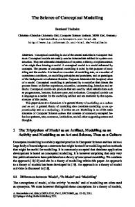
10.2 Related Work Since its inception in the 1980s, the domain of human-computer interaction (HCI) has experienced a dramatic increase in research and development, to the point where it is recognized that interaction should also be modeled just like any other aspect of an interactive system. For more than a decade, several model-based approaches have evolved in parallel in order to cope with the different challenges raised by the design and development of user interfaces in continuously evolving technological settings. We can identify various generations of works in this area [36]. The first generation of model-based approaches focused basically on deriving abstractions for graphical user interfaces (for example, UIDE [13]). At that time, user interface designers focused mainly on identifying relevant aspects for this kind of interaction modality. A second generation of approaches focused on expressing the high-level semantics of the interaction. This was mainly supported through the use of task models and associated tools, which were aimed at expressing the activities that users intend to accomplish while interacting with the application (for example, Adept [15], GTA [42], ConcurTaskTrees (CTT) [29], Trident [5], Humanoid [35]). Since then, a consensus has been reached in the community to structure interaction modelling according to different levels of abstraction in almost the same way as in other areas (i.e. database engineering and information systems). In this context, one of the most recent works is the Cameleon Reference Framework [9]. Cameleon structures the development life cycle into four levels of abstraction, starting from task specification to a running interface (see Fig. 10.1): • Task and concepts: This level considers (a) the logical activities (tasks) that need to be performed in order to reach the end users’ goals; and (b) the domain objects manipulated by these tasks. • Abstract User Interface (AUI): This level represents the user interface in terms of interaction spaces (or presentation units), independently of which interactors are available and even independently of the modality of interaction (e.g., graphical, vocal, haptic). • Concrete User Interface (CUI): This level represents the user interface in terms of “concrete interactors”, which depend on the type of platform and media available
10 Conceptual Modelling of Interaction
339
Fig. 10.1 Relationships between components in the Cameleon reference framework
and which have a number of attributes that more concretely define how the user interface should be perceived by the end user. • Final User Interface (FUI): This level consists of source code, in any programming or markup language (e.g., Java, HTML5, VoiceXML, X+V). It can then be interpreted or compiled. These levels are structured with both a relationship of reification, going from a more abstract level to a more concrete one, and a relationship of abstraction, going from a more concrete level to a more abstract one. There can also be a relationship of translation between models at the same level of abstraction, but conceived for different contexts of use. These relationships are depicted in Fig. 10.1. There are other approaches for representing the interaction based on UML models (http://www.uml.org/). Wisdom [23] is a UML-based software engineering method that proposes an evolving use-case-based method in which the software system is iteratively developed by incremental prototypes until the final product is obtained. The UML notation has been enriched with the necessary stereotypes, labeled values, and icons to allow user-centered development and a detailed user interface design. Three of its models are concerned with interaction modelling at different stages: the interaction model, at the analysis stage, and the dialog and presentation models during the design stage, as refinements of the interaction model. Another important proposal is UMLi [12], which is a set of user interface models that extends UML to provide greater support for user interface design. UMLi introduces a new diagram: the user interface diagram, which can be considered to be the first reliable proposal of UML to formally capture the user interface. However, the models are so detailed that the modelling turns out to be very difficult. Middle-sized models are very hard to specify, which may be the reason why UMLi has not been adopted in industrial environments.
340
N. Aquino, J. Vanderdonckt, J.I. Panach, and Ó. Pastor
In addition, there are several proposals that model the interaction abstractly by means of the ConcurTaskTrees (CTT) notation [29]. Examples of these types of proposals are TERESA [22] and SUIDT [4]. TERESA (Transformation Environment for inteRactivE Systems representAtions) is a tool that supports transformations in a top-down manner, providing the possibility of obtaining interfaces for different types of devices from logical descriptions. This tool starts with an overall envisioned task model and then derives concrete and effective user interfaces for multiple devices. SUIDT (Safe User Interface Design Tool) is a tool that automatically generates interfaces using several models that are related to each other: a formal functional core, an abstract task model, and a concrete task model. CTT notation is used in the abstract task model and in the concrete task model. We have mentioned different types of approaches for representing the interaction in an abstract manner. However, a suitable language that enables integration within the development environment is still needed. For this purpose, the notion of User Interface Description Language (UIDL) has emerged to express any of the aforementioned models. A UIDL is a formal language used in HCI to describe a particular user interface independently of any implementation technology. As such, the user interface might involve different interaction modalities (e.g., graphical, vocal, tactile, haptic, multimodal), interaction techniques (e.g., drag and drop), or interaction styles (e.g., direct manipulation, form fillings, virtual reality). A common fundamental assumption of most UIDLs is that user interfaces are modeled as algebraic or model-theoretic structures that include a collection of sets of interaction objects together with behaviours over those sets. The design process for a UIDL encompasses the definition of the following artefacts: • Semantics: This expresses the context, meaning, and intention of each abstraction captured by the underlying meta-models on which the UIDL is based. • Abstract syntax: This is a syntax that makes it possible to define user interface models (in accordance with the UIDL semantics) independently of any representation formalism. • Concrete syntax/es: These are (one or more) concrete representation formalisms intended to syntactically express user interface models. • Stylistics: These are graphical and textual representations of the UIDL abstractions that maximize their representativity and meaningfulness in order to facilitate understanding and communication among different people. As we have seen in this section, there are a lot of proposals to represent the interaction. Each proposal is based on a specific notation, like UML or CTT. However, as far as we know, these proposals support interaction modelling but do not support the modelling of the persistence and functionality of a system. Moreover, the works mentioned in this section have seldom been used in industrial environments. In the next section, we present an approach that has solved both of these limitations: the modelling of interaction in a holistic conceptual modelling approach and the practical applicability of interaction modelling in an industrial context. Fur-
10 Conceptual Modelling of Interaction
341
thermore, we show how the interaction can be represented by means of conceptual primitives.
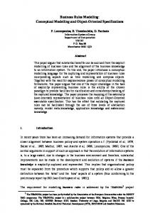
10.3 The Presentation Model of OO-Method OO-Method [27] is an object-oriented method that allows the automatic generation of software applications from conceptual models. These conceptual models are structured in four system views. (1) The Object Model specifies the static properties of the interactive application by defining the classes and their relationships. (2) The Dynamic Model controls the application objects by defining their life cycle and interactions. (3) The Functional Model describes the semantics of object state changes. (4) The Presentation Model specifies the user interface. OO-Method is supported by a commercial software suite named OlivaNOVA that was developed by CARE Technologies (http://www.care-t.com). OlivaNOVA edits the various models involved and applies subsequent transformations until the final code of a fully functional application (persistence, logic, and presentation) is generated for different computing platforms: C# or ASP running on .NET or .NET 2.0; and EJB, JSP, or JavaServer Faces running on Java. Thus, OO-Method defines a holistic conceptual model that includes the interaction perspective as well as the structural and behavioural ones. Furthermore, it is currently being used successfully in an industrial environment. This section presents the conceptual primitives of the OO-Method presentation model. These primitives allow a user interface to be modeled in a convenient way, and offer enough expressiveness to represent any management information system interface. In this section and the following, we present an illustrative example related to a photography agency system. The agency manages illustrated reports for distribution to newspaper editorials, and operates with photographers who work as independent professionals. The OO-Method presentation model is structured with a set of interaction patterns that were defined in [20]. These interaction patterns are ordered in three levels (see Fig. 10.2): • Level 1 – Hierarchical Action Tree (HAT) organizes the access to the system functionality through a tree-shaped abstraction. • Level 2 – Interaction Units (IUs) represent the main interactive operations that can be performed on the domain objects (executing a service, querying the population of a class, and visualizing the details of a specific object). • Level 3 – Elementary Patterns (EPs) constitute the building blocks from which IUs are constructed. In the next three subsections, we provide more details about the interaction patterns from these three levels, going from the most specific to the most general ones.
342
N. Aquino, J. Vanderdonckt, J.I. Panach, and Ó. Pastor
10.3.1 Elementary Patterns Elementary patterns (EPs) constitute the primitive building blocks to build IUs. They represent specific aspects of the interaction between a human and a system and cannot be combined in an arbitrary way. On the contrary, each of them is applicable in specific IUs. In the current OO-Method presentation model, there are 11 EPs that can be related to their corresponding relevant IUs (see Fig. 10.2): • Introduction captures the relevant aspects of data to be entered by the end user. Interaction aspects that can be specified include edit masks and valid value ranges. • Defined selection enables the definition (by enumeration) of a set of valid values for an associated model element. • Argument grouping defines the way in which input arguments for a given service are presented to the end user allowing these input arguments to be arranged in groups and subgroups.
Level 1
Level 2
Level 3
INTRODUCTION
DEFINED SELECTION
ARGUMENT GROUPING SERVICE INTERACTION UNIT DEPENDENCY
POPULATION PRELOAD
CONDITIONAL NAVIGATION
FILTER
HIERARCHICAL ACTION TREE
POPULATION INTERACTION UNIT
ORDER CRITERION
DISPLAY SET
INSTANCE INTERACTION UNIT
ACTIONS
NAVIGATIONS Legend A
Fig. 10.2 OO-Method presentation model
MASTER INTERACTION UNIT
B
A uses B
MASTER/DETAIL INTERACTION UNIT
DETAILS INTERACTION UNITS
10 Conceptual Modelling of Interaction
343
• Dependency enables dependency relationships to be defined between the value or state of an input argument of a service and the value or state of other input argument of the same service. The definition is based on ECA-type rules (event, condition, action). • Population preload allows the designer to specify that the selection of an object as an input argument of a service will be carried out with or without changing the interaction context. • Conditional navigation allows navigation to different IUs after the successful or failed execution of a service. In order to specify which IU to navigate to, it is also necessary to establish a condition that must hold after the execution of the service. • Filter defines a selection condition over the population of a class, which can be used to restrict the object population of the class, thereby facilitating further object search and selection operations. • Order criterion defines how the population of a class is to be ordered. Ordering is done on the values of one or more properties of the objects, taking into account ascending/descending options. • Display set determines which properties of a class are to be presented to the user and in what order. • Actions define the set of available services that can be performed on the objects of a given class. • Navigations determine the information set that can be accessed via navigation of the structural relationships found in an initial class.
10.3.2 Interaction Units An Interaction Unit (IU) describes a particular scenario of the user interface through which users are able to carry out specific tasks. In the OO-Method approach, there are three different basic kinds of interaction scenarios: execution of a service, manipulation of one object, and manipulation of a collection of objects. For each of these basic interaction scenarios, the OO-Method approach proposes a specific IU that is appropriate for handling it. A fourth IU is proposed to combine the other IUs. As shown in Fig. 10.2, the OO-Method presentation model defines these four IUs: • Service IU: enables a scenario to be defined in which the user interacts with the system in order to execute a service. The user must provide the arguments and launch the service. As shown in Fig. 10.2, six of the EPs can be used to complete the specification of a Service IU: introduction, defined selection, argument grouping, dependency, population preload, and conditional navigation. Figure 10.3 shows the final user interface generated from a Service IU. The user interface for this Service IU allows a photographer to fill in an application form for working in a photography agency. The photographer must provide personal and contact data as well as data related to its professional equipment.
344
N. Aquino, J. Vanderdonckt, J.I. Panach, and Ó. Pastor
Fig. 10.3 User interface generated from a Service IU with argument groupings (a) and defined selection (b)
• Instance IU: represents a scenario in which information about a single object is displayed, including the list of services that can be executed on it, as well as the scenarios of related information to which the user can navigate. All this information is structured by means of three EPs: display set, actions, and navigations (see Fig. 10.2). Figure 10.4 shows the final user interface generated from an Instance IU. The user interface for this Instance IU shows data related to a photographer of the agency.
Fig. 10.4 User interface generated from an Instance IU with display set (a), actions (b), and navigations (c)
10 Conceptual Modelling of Interaction
345
Fig. 10.5 User interface generated from a Population IU with filter (a), order criterion (b), display set (c), actions (d), and navigations (e)
• Population IU: represents an interaction scenario where multiple objects are presented. This scenario includes the appropriate mechanisms to do the following: select and sort objects, choose the information and available services to be shown, and list other scenarios that can be reached. All this information is structured by means of five EPs: filter, order criteria, display set, actions, and navigations (see Fig. 10.2). Figure 10.5 shows the final user interface generated from a Population IU. The user interface for this Population IU shows data related to multiple photographers of the agency at the same time. • Master/Detail IU: presents the user with a scenario for the interaction with multiple collections of objects that belong to different interrelated classes. This forms a composite scenario in which two kinds of roles can be defined: a master role, which represents the main interaction scenario, and detail roles, which represent secondary, subordinated interaction scenarios that are kept synchronized with the master role (see Fig. 10.2). Figure 10.6 shows the final user interface generated from a Master/Detail IU in which the master role corresponds to an Instance IU, which shows data related to a photographer of the agency, and the detail role corresponds to a Population IU, which shows the list of reports related to the photographer. The user interfaces depicted in Figs. 10.3–10.6 have been generated by OlivaNOVA for the desktop .NET platform.
346
N. Aquino, J. Vanderdonckt, J.I. Panach, and Ó. Pastor
Fig. 10.6 User interface generated from an Master/Detail IU with master role (a) and detail role (b)
10.3.3 Hierarchical Action Tree Once the interaction scenarios have been described through the corresponding IUs, it is necessary to determine how these IUs are to be structured, organized, and presented to the user. This structure will characterize the top level of the user interface, establishing what could be described as the main menu of the application. The Hierarchical Action Tree (HAT) serves this purpose. The HAT defines an access tree that follows the principle of gradual approximation to specify the manner in which the interactive user can access system functionality. This is achieved by arranging actions into groups and subgroups by using a tree abstraction, from the most general to the most detailed. Intermediate (i.e., non-leaf) nodes in the tree are simply grouping labels, whereas tree leaves reference pre-existing IUs (see Fig. 10.2).
10 Conceptual Modelling of Interaction
347
10.4 Explicitly Distinguishing Abstract and Concrete Interaction Modeling in OO-Method The OO-Method presentation model constitutes a unified interaction model in which there is no explicit distinction between an abstract level and a concrete level. This model can be considered a good starting point for adequately modelling interaction, since it provides a good basis to include user interface generation in the conceptual model compilation process. However, it still presents an important problem: the interaction style of the resultant software application is fixed by the model compiler, and there is no way to adapt the presentation style to the particular needs and individual tastes of end users. In this section, we show how to make this distinction feasible. We also extend the above approach in this direction, and add a concrete level that incorporates decisions related to platforms and users. In particular, the transformation templates approach is presented as a means for concrete interaction modelling.
10.4.1 Abstract Interaction Modeling As explained in Sect. 10.3, the OO-Method presentation model provides primitives that allow the designer to define user interfaces in a homogeneous and platformindependent way. All of its interaction patterns, from the three levels, capture the necessary aspects of the user interface without delving into implementation issues. In other words, the OO-Method presentation model focuses on what type of user interaction is desired, and not on how this interaction will be implemented in the resulting software product. Therefore, the OO-Method presentation model can be considered an abstract model from which the model compiler can automatically generate a user interface for different interaction modalities and platforms.
10.4.2 Concrete Interaction Modeling: Transformation Templates At the abstract level, the OO-Method presentation model does not provide primitives that allow the structure, layout, and style of user interfaces to be expressed. These decisions are delegated to the model compiler and are hard-coded in it. Thus, design knowledge and presentation guidelines are implicit and fixed in the tool that performs the model-to-code transformation and cannot be edited or customized. Thus, even though different final user interface implementations are potentially valid when moving from the abstract to the final user interface, it is not possible to adapt the user interface generation according to end user requirements and preferences. This results in the generation of predetermined user interfaces, all of which look alike, and which may not always satisfy the end user.
348
N. Aquino, J. Vanderdonckt, J.I. Panach, and Ó. Pastor
Fig. 10.7 An OO-Method presentation model and a transformation template are inputs for the model compiler
TRANSFORMATION TEMPLATE parameter1: value1, selector1 parameter2: value2, selector2 parameter3: value3, selector3 … ...
OO-METHOD PRESENTATION MODEL
MODEL COMPILER
USER INTERFACE CODE
Because of these issues, it has been necessary to extend the OO-Method presentation model with a new concrete level that provides the required expressiveness in order to enable the customization of user interfaces before their generation. An approach based on transformation templates has been defined for this purpose. A transformation template [2, 3] aims to specify the structure, layout and style of a user interface according to preferences and requirements of end users, as well as according to the different hardware and software computing platforms and environments in which the user interface will be used. A transformation template is composed of parameters with associated values that parameterize the transformations from the OO-Method presentation model to code. Figure 10.7 illustrates the use of a transformation template with OO-Method. The model compiler takes a presentation model and a transformation template as input. The transformation template provides specifications that determine how to transform the presentation model to code. The specifications are expressed by means of parameters with values and selectors. Selectors define the set of elements of the OO-Method presentation model that are affected by the value of the parameter. The transformation engine follows the specifications to generate the code. In this way, transformation templates externalize the design knowledge and presentation guidelines and make them customizable according to the characteristics of the project that is being carried out. Transformation templates can then be reused in other projects with similar characteristics. Even though the idea behind transformation templates is based on cascading style sheets [6], there are significant differences between the two approaches, with the main one being that transformation templates are applied to user interface models and not directly to the code. Another difference is that transformation templates are supposed to be used in an MDE process for user interface generation for different contexts of use, not only for web environments. Figure 10.8 depicts the main concepts or primitives that characterize the transformation templates approach. The concepts in this figure are related to context, to user interface models, and to the transformation templates themselves. These concepts are explained in the following paragraphs.
10 Conceptual Modelling of Interaction
349
10.4.2.1 Context • Context (see Fig. 10.8): refers to the context of use of an interactive system. We have defined context according to the Cameleon reference framework [9], which is widely accepted in the HCI community. According to this framework, a context of use is composed of the stereotype of a user who carries out an interactive task with a specific computing platform in a given surrounding environment. The purpose of conceptualizing context is that we want it to be possible to define different transformation templates for different contexts of use.
10.4.2.2 User Interface Models The transformation templates approach makes use of two concepts related to user interface models (see Fig. 10.8): • User interface meta-element: represents, in a generic way, any of the OO-Method interaction patterns presented in Sect. 10.3. • User interface element: represents an element of the OO-Method presentation model, that is, a specific instance of any of the above mentioned interaction patterns. Note that even though in this chapter we are presenting the transformation templates approach as an extension of OO-Method, it can also be used with other MDE approaches related to user interface development. In fact, the user interface metaelement is a generic representation of any meta-element of a user interface metamodel. Similarly, the user interface element is a generic representation of any element of a user interface model.
Context
Transformation Templates
PARAMETER TYPE
User Interface Models
VALUE TYPE
USER INTERFACE META-ELEMENT
Parameter type definition level Parameter definition level VALUE CONTEXT
TRANSFORMATION TEMPLATE
USER INTERFACE ELEMENT
PARAMETER
SELECTOR
Fig. 10.8 Main concepts of the transformation templates approach
350
N. Aquino, J. Vanderdonckt, J.I. Panach, and Ó. Pastor
10.4.2.3 Transformation Templates With regard to concepts specifically related to the transformation templates approach, we distinguish between two levels: one in which parameter types are defined, and another one in which the previously defined parameter types are instantiated as parameters in a transformation template. In the parameter type definition level, there are two concepts (see Fig. 10.8): • Value type: refers to a specific data type (e.g., integer, URI, colour, etc.) or to an enumeration of the possible values that a parameter type can assume. • Parameter type: represents a design or presentation option related to the structure, layout, or style of the user interface. We can distinguish between low-level and high-level parameter types. Low-level ones operate at the attribute level of user interfaces; for instance, colour or font type are low-level parameter types related to style. High-level parameter types operate at the concept level of user interfaces and can be used to specify the structure of the user interface, the type of components (containers, widgets) that will be used, or the alignment of the components. Defining a parameter type subsumes specifying the list of user interface metaelements that are affected by it, as well as its value type. A parameter type, with all or a set of its possible values, can be implemented in different contexts of use. In order to decide about these implementations, we propose that each possible value receive an estimation of its importance level and its development cost for different relevant contexts of use. In this way, possible values with a high level of importance and a low development cost can be implemented first in a given context, followed by those with a high level of importance and a high development cost, and so on. Possible values with a low level of importance and a high development cost would not have to be implemented in the corresponding context. For each relevant context of use, usability guidelines can be assigned to each possible value of a parameter type. These guidelines will help user interface designers in choosing one of the possible values by explaining the conditions under which the values should be used. Table 10.1 shows an example of the definition of a parameter type named grouping layout for input arguments. This parameter type is useful for deciding how to present the input arguments of a service that have been grouped using the argument grouping interaction pattern presented in Sect. 10.3.1. Table 10.1 (a) shows that this parameter type affects two interaction patterns of the OO-Method presentation model. It also shows that four different possible values have been defined. Table 10.1 (b) shows that the parameter type has been associated to two contexts of use: a desktop platform and a mobile one. For each context of use and each possible value, the importance level and development cost have been estimated. Table 10.1 (c) presents a list of usability guidelines for the desktop context and each possible value of the parameter type. These usability guidelines have been proposed from an extraction from [14].
351
10 Conceptual Modelling of Interaction Table 10.1 Parameter type: grouping layout for input arguments Parameter Type Name Grouping layout for input arguments
Affects
Possible values enumeration Value Graphical description Personal Data
Two patterns of Group box the OO-Method presentation Tabbed dialog box model: Service IU and argument grouping Wizard
Personal Data
Contact Data
Contact Data
Personal Data
Next
Accordion
Contact Data
Cancel
Ok
Cancel
Personal Data Contact Data
(a)
Possible value
Contexts SW: C# on .NET - HW: laptop or PC SW: iPhone OS - HW: iPhone Importance level Development cost Importance level Development cost
Group box Tabbed dialog box Wizard Accordion
High High Medium Low
Low Low Medium Medium
High Medium Low Medium
Low Medium High Medium
(b) Possible value
Usability guidelines (for desktop context)
Group box Tabbed dialog box Wizard
Visual distinctiveness is important. The total number of groups will be small Visual distinctiveness is important. The total number of groups is not greater than 10 The total number of groups is between 3 and 10. The complexity of the task is significant. The task implies several critical decisions. The cost of errors is high. The task must be done infrequently. The user lacks the experience it takes to complete the task efficiently Visual distinctiveness is important. The total number of groups is not greater than 10
Accordion
(c)
In the parameter definition level, there are four concepts (see Fig. 10.8): • Transformation template gathers a set of parameters for a specific context of use. • Parameter: each parameter of a transformation template corresponds to a parameter type and has both a value and a selector. • Value is an instance of a value type. The value of a parameter corresponds to a possible value of the corresponding parameter type.
352
N. Aquino, J. Vanderdonckt, J.I. Panach, and Ó. Pastor
• Selector delimits the set of user interface elements that are affected by the value of a parameter. We have defined different types of selectors that allow the designer to choose a specific user interface element; all the user interface elements of a certain type; the first or last element contained in a specific type of user interface element; or other options. Figure 10.9 represents the user interface that could be obtained for the Service IU that was presented in Fig. 10.3, if the parameter grouping layout for input arguments is applied with value wizard (see Table 10.1) and if the following two parameters are also applied: a parameter for specifying the widget to be used to display defined selections with value radio button; and a parameter for specifying the alignment of labels with value vertical.
10.5 Conclusion This chapter emphasizes the importance of interaction modelling on the same level of expressiveness as any other model involved in the development life cycle of an interactive application. In the same way that a conceptual model of the domain could be used to derive a database for a future application, a conceptual model of the interaction could be used to derive a user interface for this same application [37]. A system with a suitable functionality and persistence may be rejected by end users if the interface does not satisfy their expectations. Therefore, the designer must be provided with the suitable conceptual primitives to represent every relevant characteristic of the final interface; otherwise, a complete code generation from a conceptual model cannot become a reality. Today, the community has reached a level of progress in which this has now become a reality that goes beyond mere prototypes. In the past, model-based approaches were exploited to capture the essence of a user interface into a conceptual model of the user interface to be subsequently used for design, specification, generation, and verification. More recently, model-driven engineering (MDE) approaches have been introduced in order to make the user interface development life cycle more precise, rigorous, and systematic. The main difference between model-based approaches and model-driven engineering approaches [40, 41] is that in the former, only models are used, while in the latter all models comply with a meta-model that is itself defined according to a meta-meta-model. Similarly, all operations are captured through transformations that are themselves compliant with the same meta-model, as opposed to earlier approaches in which no meta-model was present. Not all model-based approaches for user interface development could be considered as compliant with Model-Driven Architecture (MDA) [40]. Indeed, the following MDE/MDA definition was approved unanimously by 17 participants of the ORMSC – Object and Reference Model Subcommittee of the Architecture Board of the Object Management Group (OMG) – plenary session
10 Conceptual Modelling of Interaction
353
Fig. 10.9 User interface that could be generated from a Service IU after applying different parameters
354
N. Aquino, J. Vanderdonckt, J.I. Panach, and Ó. Pastor
meeting in Montreal on 23–26 August 2004. The stated purpose of the paragraph was to provide principles to be followed in the revision of the MDA guide: “MDA is an OMG initiative that proposes to define a set of non-proprietary standards that will specify interoperable technologies with which to realize model-driven development with automated transformations. Not all of these technologies will directly concern the transformation involved in MDA. MDA does not necessarily rely on the UML, but, as a specialized kind of MDD (Model-Driven Development), MDA necessarily involves the use of model(s) in development, which entails that at least one modelling language must be used. Any modelling language used in MDA must be described in terms of the MOF (MetaObject Facility) language to enable the metadata to be understood in a standard manner, which is a precondition for any activity to perform automated transformation”.
This definition is now completely applicable to some MDE approaches for interaction modelling, such as OO-Method and its presentation model presented in this chapter. Taking this presentation model as input, we state that the interaction modelling must be divided into two views: abstract [27, 38, 39] and concrete [2, 3]. The abstract view represents what will be shown in each interface. This view corresponds to the presentation model of OO-Method, which represents the interface independently of the platform and the design. The concrete view represents how the elements will be shown in each interface. This model is built by means of transformation templates. At first glance, designers might be concerned that more effort on their part is required for modelling the concrete level. However, this problem can be resolved thanks to the use of default transformation templates for a specific context of use. Once the abstract interaction model has been specified, the concrete interaction model can be determined by just choosing the default transformation template for the context of use in which the information system is going to be used. These default transformation templates must be designed only once, and can then be reused. Designers might only have to change the value and/or scope of some parameters in order to adequate the concrete modelling to end user requirements. Future avenues of this work include: • Integration with requirements engineering. We plan to develop a method to capture interaction requirements that is compliant with holistic development based on conceptual models. These requirements would help the designer to determine the user’s needs and preferences in order to guide the interaction modelling. The capture of requirements would be based on tasks, which is the notation that is most commonly used in the HCI community. • Inclusion of a usability model in the transformation process. We will include usability characteristics in both the abstract and concrete interaction models. These characteristics will help the designer to build quality systems according to usability guidelines and heuristics. This will be helpful not only for evaluating usability during the transformation process, but also to guarantee to some extent that user interfaces issued by this approach are somewhat usable by construction [1] so as to provide a general computational framework for user interfaces [32]. • Building various transformation sets for various development paths. We will build new transformation sets that would support other development paths [17]
10 Conceptual Modelling of Interaction
355
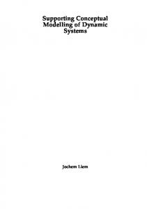
than merely forward engineering. For instance, ReversiXML [7, 8] performs reverse engineering of web pages into a concrete interface model expressed in UsiXML [18] by using derivation rules, but not transformation rules. Similarly, MultimodaliXML [33] generates multimodal user interfaces based on the same conceptual models, but involves other sets of transformation rules. • Building multi-fidelity editors for each model. We plan to develop model editors that enable modelers to rely on different levels of fidelity, not just high fidelity [19], for instance by sketching the model [11], ranging from low fidelity to high fidelity. As for any MDA approach, it is crucial to develop any work that contributes to obtain a low threshold, a high ceiling, and wide walls as much as possible to expand the capabilities of expressiveness and their transformation into a larger gamma of user interfaces. This is reflected in Fig. 10.10: the first generation of MDA software usually suffered from a high threshold (they required a high amount of resources to get some results), a low ceiling (the capabilities of the user interface generated were limited), and narrow walls (there was only one user interface generated for one computing platform). The second generation improved this situation by lowering the threshold, increasing the ceiling, and enlarging the walls. Right now, we are in the third generation, where user interface capabilities have been expanded for multiple computing platforms and contexts of use. This race is to be continued.
ty UI
Ceiling
Integrated Development Environments
Third generation
Second generation
First generation
50%
100%
Capabilities
Threshold
s pe
Resources (time, experience, …)
Walls
Fig. 10.10 Low threshold, high ceiling, and wide walls as determinants of a MDA approach
356
N. Aquino, J. Vanderdonckt, J.I. Panach, and Ó. Pastor
Acknowledgements We gratefully acknowledge the support of the ITEA2 Call 3 UsiXML project under reference 20080026; the MITYC under the project MyMobileWeb, TSI-020301-2009-014; the MICINN under the project SESAMO, TIN2007-62894, co-financed with ERDF; the Generalitat Valenciana under the project ORCA, PROMETEO/2009/015, and the grant BFPI/2008/209. Jean Vanderdonckt also thanks the FP7 Serenoa project supported by the European Commission.
References 1. Abrahão S, Iborra E, Vanderdonckt J (2008) Usability evaluation of user interfaces generated with a model-driven architecture tool. In: Law E, Hvannberg E, Cockton G (eds) Maturing usability: quality in software, interaction and value, HCI Series, vol. 10. Springer, London, pp 3–32 2. Aquino N, Vanderdonckt J, Pastor O (2010) Transformation templates: adding flexibility to model-driven engineering of user interfaces. In: Shin SY, Ossowski S, Schumacher M, Palakal MJ, Hung CC (eds) Proceedings of the 25th ACM symposium on applied computing, SAC 2010, Sierre, March 2010. ACM Press, New York, pp 1195–1202 3. Aquino N, Vanderdonckt J, Valverde F, Pastor O (2009) Using profiles to support model transformations in the model-driven development of user interfaces. In: López Jaquero V, Montero Simarro F, Molina Masso JP, Vanderdonckt J (eds) Computer-aided design of user interfaces VI, Proceedings of 7th international conference on computer-aided design of user interfaces, CADUI 2008, Albacete, June 2008. Springer, Berlin, pp 35–46 4. Baron M, Girard P (2002) SUIDT A task model based GUI-builder. In: Pribeanu C, Vanderdonckt J (eds) Task models and diagrams for user interface design: Proceedings of the first international workshop on task models and diagrams for user interface design, TAMODIA 2002, Bucharest, July 2002. INFOREC Publishing House, Bucharest, pp 64–71 5. Bodart F, Hennebert AM, Provot I, Leheureux JM, Vanderdonckt J (1994) A model-based approach to presentation: a continuum from task analysis to prototype. In: Paternò F design, specification and verification of interactives systems’94, Proceedings of the first international Eurographics workshop, Bocca di Magra, June 1994. Springer, Berlin, pp 77–94 6. Bos B, Çelik T, Lie HW, Hickson I (2007) Cascading style sheets level 2 revision 1 (CSS 2.1) specification. Technical report. World Wide Web Consortium (W3C), http://www.w3.org. Accessed 6 December 2010 7. Bouillon L, Limbourg Q, Vanderdonckt J, Michotte B (2005) Reverse engineering of web pages based on derivations and transformations. In: Proceedings of 3rd Latin American Web congress LA-Web 2005 Aires, 31 October 2005. IEEE Computer Society Press, Los Alamitos, pp 3–13 8. Bouillon L, Vanderdonckt J, Chow KC (2004) Flexible re-engineering of Web sites. In: Proceedings of 8th ACM international conference on intelligent user interfaces IUI 2004, Funchal, 13–16 January 2004. ACM Press, New York, pp 132–139 9. Calvary G, Coutaz J, Thevenin D, Limbourg Q, Bouillon L, Vanderdonckt J (2003) A unifying reference framework for multi-target user interfaces. Interact Comput 15(3):289–308 10. Chen PP (1976) The entity-relationship model – toward a unified view of data. ACM Trans Database Syst 1(1):9–36 11. Coyette A, Vanderdonckt J (2005) A sketching tool for designing anyuser, anyplatform, anywhere user interfaces. In: Costabile MF, Paternò F (eds) Proceedings of 10th IFIP TC 13 international conference on human–computer interaction, INTERACT 2005, Rome, 12–16 September 2005, Lecture Notes in Computer Science, vol 3585. Springer, Berlin, pp 550–564 12. da Silva PP, Paton NW (2003) User interface modeling in UMLi. IEEE Softw 20(4):62–69 13. Foley JD, Sukaviriya PN (1994) History, results, and bibliography of the user interface design environment (UIDE), an early model-based system for user interface design and implementation. In: Paternò F design, specification and verification of interactives systems’94. Proceed-
10 Conceptual Modelling of Interaction
14. 15.
16.
17.
18.
19.
20.
21. 22. 23. 24.
25.
26.
27. 28.
29.
357
ings of the first international Eurographics workshop, Bocca di Magra, June 1994. Springer, Berlin, pp 3–14. Galitz, WO (2002) The essential guide to user interface design: an introduction to GUI design principles and techniques. Wiley, New York Johnson P, Wilson S, Markopoulos P, Pycock J (1993) ADEPT: advanced design environment for prototyping with task models. In: Ashlund S, Mullet K, Henderson A, Hollnagel E, White TN (eds) Human–computer interaction. Proceedings of INTERACT ’93, IFIP TC13 international conference on human–computer interaction, Amsterdam, 24–29 April 1993. ACM Press, New York, p 56 Limbourg Q, Vanderdonckt J (2004) USIXML: a user interface description language supporting multiple levels of independence. In: Matera M, Comai C (eds) Engineering advanced web applications: Proceedings of workshops in connection with the 4th international conference on web engineering, ICWE 2004, Munich, 28–30 July 2004. Rinton Press, Paramus, pp 325–338 Limbourg Q, Vanderdonckt J (2009) Multi-path transformational development of user interfaces with graph transformations. In: Seffah, A, Vanderdonckt J, Desmarais M (eds) Humancentered software engineering, HCI Series. Springer, London, pp 109–140 Limbourg Q, Vanderdonckt J, Michotte B, Bouillon L, López-Jaquero V (2005) USIXML: A language supporting multi-path development of user interfaces. In: Bastide R, Palanque PA, Roth J (eds) Proceedings of 9th IFIP working conference on engineering for humancomputer interaction jointly with 11th international workshop on design, specification, and verification of interactive systems, EHCI-DSVIS 2004, Hamburg, 11–13 July 2004. Lecture Notes in Computer Science, vol 3425. Springer, Berlin, pp 200–220 Michotte B, Vanderdonckt J (2008) GrafiXML, a multi-target user interface builder based on UsiXML. In: Greenwood D, Grottke M, Lutfiyya H, Popescu M (eds) Proceedings of 4th international conference on autonomic and autonomous systems, ICAS 2008 Gosier, 16–21 March 2008. IEEE Computer Society Press, Los Alamitos, pp 15–22 Molina PJ, Meliá S, Pastor O (2002) Just-UI: a user interface specification model. In: Kolski C, Vanderdonckt J (eds) Computer-aided design of user interfaces III, Proceedings of the 4th international conference on computer-aided design of user interfaces, CADUI 2002, Valenciennes, 15–17 May 2002. Kluwer, Alphen aan den Rijn, pp 63–74 Morgan T (2004) Doing IT better. Keynote address at the 3rd conference on information systems technology and its applications, ISTA 2004. Salt Lake City, 15–17 July 2004 Mori G, Paternò F, Santoro C (2004) Design and sevelopment of multidevice user interfaces through multiple logical descriptions. IEEE Trans Softw Eng 30(8):507–520 Nunes NJ, e Cunha JF (2000) Wisdom: A software engineering method for small software development companies. IEEE Software 17(5):113–119 Olivé A (2005) Conceptual schema-centric development: a grand challenge for information systems research. In: Pastor O, e Cunha JF (eds) Advanced information systems engineering, Proceedings of 17th international conference, CAiSE 2005, Porto, 13–17 June 2005, Lecture Notes in Computer Science, vol 3520. Springer, Berlin, pp 1–15 Pastor O (2006) From extreme programming to extreme non-programming: is it the right time for model transformation technologies? In: Bressan S, Küng J, Wagner R (eds) Proceedings of 17th international conference on database and expert systems applications, DEXA 2006, Krakow 4–8 September 2006, Lecture Notes in Computer Science, vol 4080. Springer, Berlin, pp 64–72 Pastor O, e Cunha JF (eds) Advanced information systems engineering, Proceedings of 17th international conference, CAiSE 2005, Porto, 13–17 June 2005, Lecture Notes in Computer Science, vol 3520. Springer, Berlin Pastor O, Molina JC (2007) Model-driven architecture in practice: a software production environment based on conceptual modeling. Springer, Secaucus Paternò F (ed) (1994) Design, specification and verification of interactive systems’94, Proceedings of the first international Eurographics workshop, 8–10 June 1994, Bocca di Magra. Springer, Berlin Paternò F. (1999) Model-based design and evaluation of interactive applications. Springer, London
358
N. Aquino, J. Vanderdonckt, J.I. Panach, and Ó. Pastor
30. Paternò F, Santoro C, Spano LD (2009) MARIA: a universal, declarative, multiple abstractionlevel language for service-oriented applications in ubiquitous environments. ACM Trans Comput-Hum Interact, 16(4) 31. Pederiva I, Vanderdonckt J, España S, Panach JI, and Pastor O (2007) The beautification process model-driven engineering of user interfaces. In: Baranauskas MCC, Palanque PA, Abascal J, Barbosa SDJ (eds) Proceedings of 11th IFIP TC 13th international conference on human–computer interaction, INTERACT 2007, Río de Janeiro, 10–14 September 2007, Lecture Notes in Computer Science, vol 4662. Springer, Berlin, pp 411–425 32. Puerta AR, Eisenstein J (1999) Towards a general computational framework for model-based interface development systems, Knowl-Based Syst 12(8):433–442 33. Stanciulescu A, Limbourg Q, Vanderdonckt J, Michotte B, Montero F (2005) A transformational approach for multimodal web user interfaces based on UsiXML. In: Lazzari G, Pianesi F, Crowley JL, Mase K, Oviatt SL (eds) Proceedings of the 7th international conference on multimodal interfaces, ICMI 2005, Trento, 4–6 October 2005. ACM Press, New York, pp 259–266 34. Stevens WP, Myers GJ, Constantine LL (1974) Structured Design. IBM Syst J 13(2):115–139 35. Szekely PA (1990) Template-based mapping of application data interactive displays. In: Hudson SE (ed) Proceedings of the 3rd annual ACM symposium on user interface software and technology, UIST 1990, Snowbird, 3–5 October 1990. ACM Press, New York, pp 1–9 36. Szekely PA (1996) Retrospective and challenges for model-based interface development In: Bodart F, Vanderdonckt J (eds) Design, specification and verification of interactive systems’96, Proceedings of the 3rd International Eurographics workshop, Namur, 5–7 June 1996. Springer, Berlin, pp 1–27 37. Torres I, Pastor O, Limbourg Q, Vanderdonckt J (2005) Una experiencia práctica de generación de interfaces de usuario a partir de esquemas conceptuales. In: Puerta AR and Gea M (eds) Proceedings of VI congreso interacción persona ordenador, Interacción 2005 – CEDI 2005, Granada, 13–16 September 2005. Thomson Paraninfo, Madrid, pp 401–404 38. Valverde F, Panach JI, Aquino N, Pastor O (2009) New trends on human–computer interaction. Research, development, new tools and methods. Dealing with abstract interaction modelling in an MDE development process: a pattern-based approach. Springer, London, pp 119–128 39. Valverde F, Panach JI, Pastor O (2007) An abstract interaction model for a MDA software production method. In: Grundy JC, Hartmann S, Laender AHF, Maciaszek LA, Roddick. JF (eds) Challenges in conceptual modelling. Proceedings of tutorials, posters, panels and industrial contributions at the 26th international conference on conceptual modeling, ER 2007, Auckland, 5–9 November 2007, CRPIT, vol 83. Australian Computer Society, pp 109–114 40. Vanderdonckt J (2005) A MDA-compliant environment for developing user interfaces of information systems. In: Pastor O, e Cunha JF (eds) Advanced information systems engineering, Proceedings of 17th international conference, CAiSE 2005, Porto, 13–17 June 2005, Lecture Notes in Computer Science, vol 3520. Springer, Berlin, pp 16–31 41. Vanderdonckt J (2008) Model-driven engineering of user interfaces: promises, successes, and failures. In: Buraga S, Juvina I (eds) Proceedings of 5th annual Romanian conference on human–computer interaction ROCHI’2008, Iasi, 18–19 September 2008. Matrix ROM, Bucarest, pp 1–10 42. Van Der Veer GC, Lenting BF, Bergevoet BAJ (1996) GTA: groupware task analysis – modeling complexity. Acta Psychol 1:297–322
http://www.springer.com/978-3-642-15864-3