From MITL to Timed Automata? Oded Maler1 , Dejan Nickovic1 and Amir Pnueli2,3 1
3
Verimag, 2 Av. de Vignate, 38610 Gi`eres, France [Dejan.Nickovic | Oded.Maler]@imag.fr 2 Weizmann Institute of Science, Rehovot 76100, Israel New York University, 251 Mercer St. New York, NY 10012, USA
[email protected]
Abstract. We show how to transform formulae written in the real-time temporal logic MITL into timed automata that recognize their satisfying models. This compositional construction is much simpler than previously known and can be easily implemented.
Prediction is very difficult, especially about the future. Niels Bohr
1 Introduction Decision procedures for model-checking of temporal logic formulae [MP91,MP95] play a central role in algorithmic verification [CGP99]. Such procedures are based, in the linear-time context, on deriving from a formula ϕ an automaton-like device that accepts exactly sequences of states or events that satisfy it [VW86]. For discretetime models, used for functional verification of software or synchronous hardware, the logical situation is rather mature. Logics like LTL (linear-time temporal logic) or CTL (computation-tree logic) are commonly accepted and incorporated into verification tools. LTL admits a variety of efficient algorithms for translating a formula into an equivalent automaton [GPVW95,SB00,GO01,KP05] and it even underlies the industrial standard PSL [KCV04,HFE04]. When considering timed models and specification formalisms whose semantics involves the time domain R+ rather than N, the situation is somewhat less satisfactory [A04]. Many variants of real-time logics [Koy90,AH92a,Hen98,HR04] as well as timed regular expressions [ACM02] have been proposed but the correspondence between simply-defined logics and variants of timed automata (automata with auxiliary clock variables [AD94]) is not as simple and canonical as for the untimed case, partly, of course, due to the additional complexity of the timed model. Consequently, existing verification tools for timed automata rarely use temporal properties other than safety. One of the most popular dense-time extensions of LTL is the logic MITL introduced in [AFH96] as a restriction of the logic MTL [Koy90]. The principal modality of MITL is the timed until UI where I is some non-singular interval. A formula p U[a,b] q is ?
This work was partially supported by the European Community project IST-2003-507219 PROSYD (Property-based System Design).
satisfied by a model at any time instant t that admits q at some t0 ∈ [t + a, t + b], and where p holds continuously from t to t0 . The decidability of MITL was established in [AFH96] and it was, together with MTL, subject to further investigations [AH92b,RSH98,HRS98,OW05]. However, the automaton construction in [AFH96] is very complicated (11 pages) and, to the best of our knowledge, has never been implemented. The only logic that has been integrated into a real-time model-checking tool was the timed version of CTL, TCTL [HNSY94], used in the tool Kronos [Y97]. 4 In this paper we remedy this situation somewhat by presenting a simple construction of timed automata that accept exactly models of MITL formulae. The construction is based on two ideas, the first being the modular construction of property testers for untimed formulae [KP05] and the other is the observation, similar to the one already made in [AFH96], that the evolution over time of the satisfiability of a formula of the form p U[a,b] q is of bounded variability, regardless of the variability of p and q. The rest of the paper is organized as follows. In Section 2 we illustrate the modular construction of testers for (untimed) LTL formulae. The logic MITL is presented in Section 3 together with its semantic domain (Boolean signals) and timed automata. The main result, the construction of property testers for MITL, is presented in Section 4, followed by a brief discussion of the differences between the version of MITL that we use and the one presented in [AFH96].
2 Temporal Testers for LTL In this section we discuss some of the problems associated with the construction of automata that accept models of LTL formulae, and describe the modular procedure of [KP05] which we later extend for MITL. We feel that, independently of its timed generalization, this construction, based on composition of acausal sequential transducers, improves our understanding of temporal logic and can serve as a unifying framework for both verification and monitoring. We assume familiarity with basic notions of LTL, whose syntax is defined according to the grammar ϕ := p | ¬ϕ | ϕ1 ∨ ϕ2 | ϕ | ϕ1 Uϕ2 where p belongs to a set P = {p1 , . . . , pn } of propositions. LTL is interpreted over n-dimensional Boolean ω-sequences of the form ξ : N → Bn . We abuse p to denote the projection of the sequence ξ on p. The semantics of LTL formulae is typically given via a recursive definition of the relation (ξ, t) |= ϕ indicating that the sequence ξ satisfies ϕ at position t. The satisfaction of a compound formula op(ϕ1 , ϕ2 ), where op is a temporal or propositional operator, by a sequence ξ is an op-dependent function of the satisfaction of the sub formulae ϕ1 and ϕ2 by ξ. Functionally speaking, the satisfaction of ϕ by arbitrary sequences can be viewed as a characteristic function χ ϕ which maps sequences over Bn into Boolean sequences such that β = χϕ (ξ) means that for every i, β[i] = 1 iff (ξ, i) |= ϕ. The semantics of LTL can thus be formulated5 as a recursive 4
5
An efficient emptiness checking algorithm for timed B¨uchi automata has been proposed and implemented in [TYB05] but without an upstream translation from a logical formalism. Throughout the paper we use a variant of until in which p U q requires that p holds also at the same time instant when q becomes true, which can be expressed as p U (p ∧ q) using the
definition of χϕ : χp [t] χ¬ϕ [t] χϕ1 ∨ϕ2 [t] χ ϕ [t] χϕ1 U ϕ2 [t]
= = = = =
p[t] ¬χϕ [t] χϕ1 [t] ∨ χϕ2 [t] ϕ χ W [t + 1]ϕ2 0 V ϕ1 00 t0 ≥t (χ [t ] ∧ t00 ∈[t,t0 ] χ [t ])
(1)
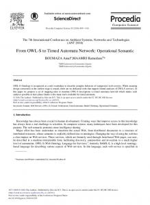
Given a formula ϕ, its characteristic function is defined as a composition of sequential functions, following the pattern of its parse tree, as illustrated in Figure 1. So what remains to be done is to build an automaton that realizes the appropriate sequential function for each LTL operator and use these building blocks, that we call temporal testers, to construct a mechanism that computes the characteristic function for arbitrary formulae, but some problem related to causality should be settled first.
p1 = χ p 1
p2 = χ p 2
p3 = χ
χ ¬
χ p1
∨
¬p2
U
χ( p1 )∨(¬p2 U p3 )
χ¬p2 U p3
p3
Fig. 1. Computing the characteristic function of ( p1 ) ∨ (¬p2 U p3 ).
A sequential function f : Aω → B ω is said to be causal if for every u ∈ A∗ , v, v 0 ∈ B ∗ such that |u| = |v| = |v 0 | and every α ∈ Aω and β ∈ B ω f (u · α) = v · β and f (u · α0 ) = v 0 · β 0 implies v = v 0 . In other words, the value of f (α) at time t may depend only on the values {α[t 0 ] : t0 ≤ t}. Causal functions are realized naturally by deterministic automata with output (sequential synchronous transducers). However, unlike the semantics of the past fragment of LTL which is causal (see [HR02]), the semantics of future LTL is not. Looking closely at (1) we can see that while the propositional operators define causal sequential functions, the future temporal operators are acausal. The output of the next operator at time t depends on the input at t + 1 and, even worse, the output of the until operator at t may depend on input values at some t0 which may be arbitrarily further in the future. One can think of two ways to realize acausal sequential functions. The first approach, which works well for operators with a bounded level of acausality, such as the next operator or several nestings of which (denoted by d ) is to dissociate the time scales of the input and the output. That is, let the automaton ignore the first d input standard interpretation. For LTL this variation just simplifies the corresponding tester while for MITL it avoids certain anomalies.
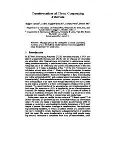
symbols, and then let β[t] = α[t + d]. Unfortunately this does not always work for unbounded acausality. Using the second approach the transducer responds to the input synchronously but since at time t the information might not be sufficient for determining the output, it will have to “guess” the output non-deterministically and split the computation into two runs, one that predicts 0 and one that predicts 1. Each of the runs needs to remember its predictions until sufficient input information is accumulated to abort all but one run. The automaton for operators with acausality of depth d, may need to memorize up to 2d predictions. The first approach is more intuitive6 but since we do not know how to extend it to unbounded acausality, we use the second one. The automaton that computes the characteristic function of is depicted in Figure 2 along with a sample run. 7 State s0 indicates that the prediction made in the previous step was 0, hence at this state, observing p contradicts the prediction and the run is aborted. Input p confirms the prediction and the run splits by generating two predictions for the next value and so on. For every infinite input sequence ξ, only one infinite run survives and its output is χ p (ξ). The automaton for d p follows the same pattern and is nothing but an output-driven shift register of depth d (see Figure 2). States s00 and s01 of this automaton represent predictions for unsatisfiability at t − 2 and hence admit only p-labeled transitions. It is worth mentioning that these automata are output-deterministic and can be obtained by reversing the transitions in the ordinary input-driven shift registers that correspond to the past temporal operator previously, also known as the delay operator z −1 .
p/1 p/0
s0
s1
p/1
p/0
p/0
p/1
s0
p/0
s00
s1 p/0
p/0
s0
p/1
s11 p/1
p/1
s01
p/1 p/0
s1 p/0
p/0 s10
p/1
s0 p/1
p/0 ···
s1 p/1 ···
Fig. 2. The testers for p and for ( p); An initial fragment of the behavior for the p-tester while computing χ (pppp · · · ) = 110 · · · . 6 7
After all, it is more natural to reply “I don’t know yet” rather than saying “the answer now could be either 0 or 1, but only in the next step I will tell you which of them is actually true”. To ease readability we use {p, p} instead of {0, 1} as the input alphabet for unary operators and {pq, pq, pq, pq} for the binary ones. Moreover, we use p as a shorthand for {pq, pq}.
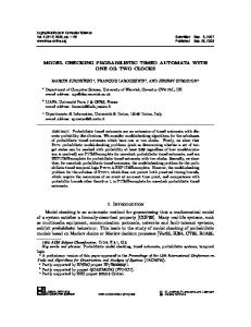
The situation with p U q is more involved because a priori, due to the unbounded horizon, one might need to generate and memorize 2ω predictions. However the semantics of until implies that at most two confirmable predictions may co-exist simultaneously. Lemma 1. Let β = χp U q (ξ). Then for every t such that ξ[t] = ξ[t + 1] = pq, β[t] = β[t + 1]. Proof. There are three possibilities: 1) The earliest t0 > t + 1 such that β[t0 ] 6= pq satisfies β[t0 ] = pq. In that case, the property is satisfied at t and t + 1; 2) The same t0 satisfies β[t0 ] = p and the property is falsified at both t and t + 1; 3) β[t0 ] = pq for every t0 > t + 1 and the property is falsified from both time points.8 This fact is reflected by the tester of Figure 3. At time instants where p is observed, the value of the output is determined to be 0. Likewise when pq is observed the output is determined to be 1. The only situation that calls for non-determinism is when pq occurs and we do not know in which of the three cases of Lemma 1 we will eventually find ourselves. Hence we split the run into positive and negative predictions (states s pq and spq , respectively). The only input sequences that will lead to two infinite runs are those ending with an infinite suffix of pq’s. To choose the correct one among the two we add a B¨uchi condition requiring infinitely many visits in the set {sp , spq , spq } which amounts to rejecting runs that stay forever in spq . With these two testers (and simple testers for the Boolean operators) one can build testers for arbitrary LTL formulae. Note that in both the next and until testers, all transitions entering a state are decorated by the same output symbols so, in fact, one might view outputs as associated with states rather than with transitions, as is done in [KP05]. The notion of compositional temporal testers, as introduced in [KP05], is based on several key ideas. One of them is the allocation of an individual Boolean variable to each sub-formula of an LTL formula. This idea, to which we refer in [KP05] as statification of the sub-formula, has been considered first in [BCM+ 92] in the context of symbolic implementation of a tableau construction. The observation that such a Boolean variable can replace the sub-formula itself in the context of model checking has been considered in [CGH94]. It is worth mentioning the translation of LTL to alternating automata [Var96] which, like the temporal testers approach, works inductively on the structure of the formula but not in a compositional manner.
3 Signals, their Temporal Logic and Timed Automata Extending the construction of temporal testers from discrete to dense time requires adaptations of the semantic domain, the logic and the automata. The interaction between discrete transitions and dense time may give rise to certain anomalies and complications that we avoid by deviating slightly from the original definitions of [AFH96]. 8
This is the “strong” interpretation of until. For the weak version both t and t + 1 will satisfy the property.
p/0 sp
pq/0 pq/0
spq
p/0
sp p/0
spq pq/0
spq pq/1
spq pq/1
pq/1 pq/1 spq
p/0 pq/1
pq/0 spq
pq/1 pq/1
pq/1
Fig. 3. The tester for p U q for sequences (left) and for signals (right). All states except spq are accepting. All transitions in the signal tester should be decorated by z > 0/z := 0, with z being an auxiliary clock, to force signals to maintain each value for a non-punctual duration.
3.1 Signals Two basic semantic domains for describing timed behaviors have been introduced in an algebraic form in [ACM02,A04]. The first semantic objects are the time-event sequences, elements of the free product (shuffle) of the monoids Σ ∗ and R+ . Time-event sequences consist of instantaneous events (or finite sequences of events) separated by numbers that represent time durations. The other semantic domain is that of signals, elements of the free product of several copies of the monoid R+ , a copy for each alphabet symbol. Signals are thus viewed as concatenations of “typed” real numbers, where σ15 · σ23 represents a σ1 period of duration 5 followed by a σ2 period of duration 3. Zero is the identity element of each of the monoids and it is absorbed when signals are transformed to a canonical form, that is σ1t1 · σ 0 · σ2t2 = σ1t1 · σ2t2 . A signal-event monoid containing both can be defined as well [ACM02]. The transformation of these objects into the form of functions from the time domain to the alphabet is not painless. For time-event sequences a “super-dense” time [MMP92] had to be invented, a subset of the product of R+ and N, where a sequence of discrete events, all taking place at time t, is mapped to the sequence (t, 1), (t, 2), . . . of generalized time instants. The timed traces of [AD94] constitute another representation of the same objects. Signals, which are the natural domain for MITL, are more well-behaving in this respect and can be mapped bijectively to functions from R + to the alphabet if one accepts some restrictions. The one we adopt is to view a signal of the form σ 1t1 · σ2t2 as a function whose value is σ1 in the left-closed right-open interval [0, t1 ) and σ2 in the interval [t1 , t1 + t2 ). Since such intervals cannot be punctual without being empty, we exclude from the discussion signals that may have a distinct value in some isolated point.9 Since our construction is based on characteristic functions and signal transduc9
Other possibilities are left-open right-closed intervals with the exclusion of time zero, or a non-bijective representation which may map the algebraic object into two time functions that differ on t1 .
ers, we need this property of signals to be preserved by the temporal operators, hence we deviate from [AFH96] by restricting the quantitative temporal modalities to closed intervals. Definition 1 (Signals). Let R+ be the set of non-negative real numbers. A Boolean signal is a function ξ : R+ → Bn such that for every σ ∈ Bn , ξ −1 (σ) is a union of left-closed right-open intervals. A partial signal is a restriction of a signal to some interval [a, b). We will sometimes refer to a partial signal of the form σ1t1 · σ2t2 · · · σktk as a σ1 · σ2 · · · σk -segment of the signal. 3.2 Real-time Temporal Logic The syntax of MITL is defined by the grammar ϕ := p | ¬ϕ | ϕ1 ∨ ϕ2 | ϕ1 U[a,b] ϕ2 | ϕ1 Uϕ2 where p belongs to a set P = {p1 , . . . , pn } of propositions and b > a ≥ 0 are rational numbers (in fact, using normalization, it is sufficient to consider integers). From basic MITL operators one can derive other standard Boolean and temporal operators, in particular the time-constrained eventually and always operators 3[a,b] ϕ =
T
U[a,b] ϕ
and
2[a,b] ϕ = ¬3[a,b] ¬ϕ.
We interpret MITL over n-dimensional Boolean signals and define the satisfiability relation via characteristic functions, which for the propositional operators and the untimed until are defined exactly as for LTL. The semantics of timed until is given by V W ϕ1 00 ϕ2 0 χϕ1 U[a,b] ϕ2 [t] = t00 ∈[t,t0 ] χ [t ]) t0 ∈[t+a,t+b] (χ [t ] ∧
The difference with respect to untimed until is that t0 ranges over the bounded (but dense) interval [t+a, t+b] rather than over the unbounded set {t, t+1, . . .} of integers. Our interpretation of the timed until slightly deviates from [AFH96] by requiring ϕ 1 to hold also at the moment t0 when ϕ2 becomes true, and not only in the open interval (t, t0 ). A signal ξ satisfies the formula ϕ iff χϕ (ξ)[0] = 1. The following lemma, proved also in [DT04], shows that timed until can be expressed by a combination of untimed until and timed eventually whose characteristic function is W ϕ 0 χ3[a,b] ϕ = t0 ∈[t+a,t+b] χ [t ]. Lemma 2 (Timed Until is Redundant). For every signal ξ,
ξ |= pU[a,b] q ↔ ξ |= 2[0,a] (p U q) ∧ 3[a,b] q. Proof: One direction of the equivalence follows directly from the semantics of timed until, so we will consider only the other direction which is proved via the following observations:
1. If ξ |= 2[0,a] p U q then p is continuously true throughout [0, a]. 2. If ξ |= 2[0,a] p U q, then p U q has to hold at a and hence there exists t0 ≥ a such that q is true at t0 and p holds during [a, t0 ]. 3. Formula 3[a,b] q requires the existence of t0 ∈ [a, b] such that q holds at t0 Combining these observations we can see that ξ |= 2[0,a] (p U q) ∧ 3[a,b] q implies that there exists t0 ∈ [a, b] such that q is true at t0 and p holds continuously during [0, t0 ], which is exactly the semantic definition of p U[a,b] q. For the sake of completeness, let us mention that the special case p U[0,b] q can be written as p U q ∧ 3[0,b] q, and that p U[a,∞) q, which is not allowed by our syntax, can be written as 2[0,a] (p U q). 3.3 Timed Automata We use a variant of timed automata which differs slightly from the classical definitions [AD94,HNSY94,Alu99] as it reads multi-dimensional dense-time Boolean signals, and outputs Boolean signals. Hence the input and output alphabet letters are associated with states rather than with transitions. We also extend the domain of clock values to include the special symbol ⊥ indicating that the clock is currently inactive 10 and extend the order relation on R+ accordingly by letting ⊥ < v for every v ∈ R+ . For a set A ⊆ Rn we use cl(A) to denote its closure (in the topological sense). The set of valuations of a set C = {x1 , . . . , xn } of clock variables, each denoted as v = (v1 , . . . , vn ), defines the clock space H = (R+ ∪ {⊥})n . A configuration of a timed automaton is a pair of the form (q, v) with q being a discrete state. For a clock valuation v = (v1 , . . . , vn ), v + t is the valuation (v10 , . . . , vn0 ) such that vi0 = vi if vi = ⊥ and vi0 = vi + t otherwise. A clock constraint is a conjunction of conditions of the form x ≤ d, x < d, x ≥ d or x > d for some integer d. Definition 2 (Timed Signal Transducer). A timed signal transducer is a tuple A = (Σ, Q, Γ, C, λ, γ, I, ∆, q0 , F ) where Σ is the input alphabet, Q is a finite set of discrete states, Γ is the output alphabet and C is a set of clock variables. The input labeling function λ : Q → Σ associates an input letter to every state while the output function γ : Q → Γ assigns output letters. The staying condition (invariant) I assigns to every state q a subset Iq of H defined by a conjunction of inequalities of the form x ≤ d or x < d, for some clock x and integer d. The transition relation ∆ consists of elements of the form (q, g, ρ, q 0 ) where q and q 0 are discrete states, the transition guard g is a subset of H defined by a clock constraint and ρ is the update function, a transformation of H defined by an assignment of the form x := 0 or x := ⊥. Finally q0 is the initial state and F ⊆ 2Q is a generalized B¨uchi acceptance condition. The behavior of the automaton as it reads a signal ξ consists of an alternation between time progress periods where the automaton stays in a state q as long as ξ[t] = λ(q) and Iq holds, and discrete instantaneous transitions guarded by clock conditions. Formally, a step of the automaton is one of the following: 10
This is syntactic sugar since clock inactivity in a state can be encoded implicitly by the fact that in all paths emanating from the state, the clock is reset to zero before being tested [DY96].
σ t /τ t
– A time step: (q, v) −→ (q, v + t), t ∈ R+ such that σ = λ(q), τ = γ(q), and11 v + t ∈ cl(Iq ). δ
– A discrete step: (q, v) −→ (q 0 , v 0 ), for some transition δ = (q, g, ρ, q 0 ) ∈ ∆, such that v ∈ g and v 0 = ρ(v) A run of the automaton starting from a configuration (q0 , v0 ) is a finite or infinite sequence of alternating time and discrete steps of the form ξ:
σ
t1
/τ
t1
δ
σ
t2
/τ
t2
δ
1 2 (q0 , v0 ) 1−→1 (q0 , v0 + t1 ) −→ (q1 , v1 ) 2−→2 (q1 , v1 + t2 ) −→ ··· ,
P such that ti diverges. A run is accepting if for every F ∈ F, the set of time instants in which it visits states in F is unbounded. The input signal carried by the run is σ 1t1 · σ2t2 · · · and the output is τ1t1 · τ2t2 · · · The automaton realizes a sequential relation fA over its input and output alphabets defined by fA (ξ) = ξ 0 iff the accepting run induced by the input signal ξ, outputs the signal ξ 0 .
4 Main Result In this section we show how to build for every MITL formula ϕ a property tester, a timed signal transducer Aϕ whose associated sequential function coincides with the characteristic function of ϕ, that is, fAϕ = χϕ . The construction follows the pattern of the untimed one by composing testers corresponding to operators that appear in the formula. The tester for the untimed until can be easily adapted to signals by associating input and output symbols with states and removing self loops (see Figure 3). The only missing link is the following proposition. Proposition 1. One can construct a timed signal transducer that realizes χ 3[a,b] p . The construction used to prove this proposition follows the lines of the untimed one, based on generating output predictions non-deterministically and aborting them when they are contradicted by actual values of p in ξ. Dense time, however poses new problems because the set of potential predictions of bounded duration includes signals with an arbitrary number of switchings between true and false, and such predictions cannot be memorized by a finite-state timed device. We first show in the following lemma, also used in [AFH96], that predictions that switch too frequently cannot be true for any sub formula of type 3[a,b] p. A similar property was used in [MNP05] to show that past MITL is deterministic. We use the auxiliary variable u for the output of the tester. Lemma 3. Let β be a Boolean signal satisfying β = χ3[a,b] p (ξ) for 0 ≤ a < b and some arbitrary ξ. Then for any factorization β = v ·0r1 ·1r2 ·0r3 ·w we have r2 ≥ b−a. 11
Note that we have chosen Iq to be “backward-closed” so that v +t ∈ cl(Iq ) implies v +t0 ∈ Iq for every t0 , 0 ≤ t0 < t.
Proof: The following observation concerning the constraints on the values of u and p at every t follows from the definitions: if p holds at t + b, u must hold throughout the interval [t, t + b − a]. Let [t1 , t2 ) be the corresponding interval for 1r2 . Since t1 is the first instant where u holds, p must start holding at t1 + b and not before that, because otherwise this would imply that u holds before t1 , contrary to our assumptions. Following the observation, u has to hold during the entire interval [t 1 , t1 + b − a]. Consequently, t2 ≥ t1 + b − a and we are done. r1
r2 t1
r3 t2
Fig. 4. A signal χ3[a,b] p (ξ) for an arbitrary ξ.
The importance of this property is that it bounds the variability of any realizable prediction and constrains the relation between the number of changes and the duration of candidate signals. Let d = b − a and m = db/de + 1. Since every 12 10 or 01 segment of β has at least d duration, any acceptable prediction of the form (01) m or (10)m has a duration beyond b and, hence, its initial segment can be forgotten. Consequently, 2m clocks suffice to memorize relevant predictions. Let us first explain our construction in discrete time where 3[a,b] is just syntactic sugar: _ 3[a,b] p ≡
i p i∈[a,b]
As this operator is bounded by d = b − a, a tester will need to remember at most 2 d predictions, which can be encoded explicitly as states that correspond to elements of B d . For obvious reasons, this approach will not extend to dense time. Instead, we can encode such sequences by the length (duration) of their 0 and 1 segments as is done in data compression. For example, the sequence 00011011 can be encoded as 0 3 12 01 12 . This information can be memorized by an automaton augmented with additional discrete clocks (counters), each reset upon a change between 0 and 1, and incremented at each step. For this example, assuming x1 is reset at the first 0, y1 reset at the subsequent occurrence of 1, and so on, we reach the end of the sequence with x 1 = 8, y1 = 5, x2 = 3 and y2 = 2. With such a “symbolic” representation, the relevant past predictions at any time instant are identified via conditions on the clocks, which are used to admit or reject actual values of the input. Our construction does exactly that in dense time. Due to the symbolic encoding of states, it is simpler to decompose the tester into two parts, as depicted in Figure 5: a prediction generator (Figure 6) which generates output signals non-deterministically and the checker (Figure 7) which checks whether actual inputs confirm these predictions. 12
To be more precise, the first 10 segment can be arbitrarily small.
Generator
χ3[a,b] p (ξ)
x1 . . . y m ξ
Checker
Fig. 5. The architecture of the tester for 3[a,b] p.
The generator simply generates arbitrary Boolean signals subject to the sole restriction of bounded variability, according to Lemma 3. This condition is imposed via the guards of the form yi ≥ b − a on all transitions from 1 to 0. The values of the 2m clocks x1 , . . . xm and y1 . . . ym represent at time t the form of the prediction segment at the time window [t − b, t]. Clocks whose value cross b become inactive and can be re-used to memorize new events. This way the denotation of the clocks shifts circularly, and the value of the active clocks always represents the boundaries of the relevant prediction segments. To see that the checker indeed aborts all but correct predictions observe a prefix of its behavior as it moves through states {s1 , s2 , s3 } trying to match prediction to input (see Figure 8). The negative prediction segment at [t0 , t1 ) forbids p anywhere in the interval t0 + a, t1 + b) and this is guaranteed by forcing the checker to be at the p-state s1 from the time x1 ≥ a until the time y1 = b. At time t1 + b, p must be observed and a transition to s2 is taken. The positive prediction interval requires p to hold during the interval [t1 + b, t2 + a) (which corresponds to the clock conditions y1 ≥ b and x2 < a) except, possibly, for short episodes of p that last less than b − a time. This is reflected in the transition from s2 to s3 which resets the clock z. If z = b − a and we are still in s3 , the run is aborted. When x2 ≥ a we arrive to a new negative prediction segment and move to the next identical segment of the automaton. This bounded operator requires no B¨uchi condition, and the proof of Proposition 1 is concluded. To complete the construction for MITL we just need to compose the testers for the propositional, untimed and timed operators according to the structure of the formula. The parallel composition of transducers is fairly standard and we give only the definition of an input-output composition of signal transducers A1 . A2 where the output of A1 is the input of A2 . Note that the need for a generalized B¨uchi condition comes from such a composition of testers for unbounded operators as we need to identify accepting runs of A2 triggered by outputs of accepting runs of A1 . Definition 3 (I/O Composition). Let A1 = (Σ 1 , Q1 , Γ 1 , C 1 , λ1 , γ 1 , I 1 , ∆1 , q01 , F 1 ) and A2 = (Σ 2 , Q2 , Γ 2 , C 2 , λ2 , γ 2 , I 2 , ∆2 , q02 , F 2 ) be timed signal transducers such that Γ 1 = Σ 2 . Their I/O composition is the transducer A = A1 . A2 = (Σ 1 , Q, Γ 2 , C, λ, γ, I, ∆, q0 , F )
/x1 := y1 := . . . := xm := ym := ⊥ /x1 := 0 /0
/y1 := 0
/y1 := 0
/0
/1
x1 ≥ b/x1 := ⊥
y1 ≥ b − a/ x2 := 0
y1 ≥ b/y1 := ⊥
/y2 := 0
/1 ... y2 ≥ b − a/ x3 := 0
... /0
/ym := 0
/1
ym ≥ b − a/ x1 := 0 Vm
i:=1
xi < b ∧
Vm
i:=1
xm ≥ b/xm := ⊥ ym ≥ b/ym := ⊥
yi < b
Fig. 6. The prediction generator. We use a StateChart-like notation when several states admit the same transition or staying condition.
where
Q = {(q 1 , q 2 ) ∈ Q1 × Q2 s.t. γ 1 (q 1 ) = λ2 (q 2 )},
C = C 1 ∪C 2 , λ(q 1 , q 2 ) = λ1 (q 1 ), γ(q 1 , q 2 ) = γ 2 (q 2 ), I(q1 ,q2 ) = Iq11 ∩Iq22 , q0 = (q01 , q02 ) and F = F 1 ∪ F 2 . The transition relation ∆ is the restriction to Q of the set of all transitions of either of the following forms ((q 1 , q 2 ), g 1 ∩ g 2 , ρ1 ||ρ2 , (q 01 , q 02 )) ((q 1 , q 2 ), g 1 ∩ Iq2 , ρ1 , (q 01 , q 2 )) ((q 1 , q 2 ), Iq1 ∩ g 2 , ρ2 , (q 1 , q 02 )) such that (q 1 , g 1 , ρ1 , q 01 ) ∈ ∆1 and (q 2 , g 2 , ρ2 , q 02 ) ∈ ∆2 . It is not hard to see that A1 . A2 realizes the sequential function obtained by composing the sequential functions realized by A1 and A2 . Corollary 1 (Main Result). MITL formulae can be transformed into timed automata using a simple procedure. This construction provides a decision procedure for MITL by emptiness checking. Following the results in [TYB05,Tri06], timed B¨uchi emptiness checking can be reduced to the search of accepting cycles in the zone-closed simulation graph, which is generated in practice by timed verification tools such as K RONOS citekronos, U PPAAL [LPY97]
x1 ≥ 0/
y1 ≥ 0/
x1 < a x1 ≥ a s1
p
y1 < a
y1 ≥ a/ y1 ≥ b/
s2
y1 ≥ a/ z := 0
/z := 0
p
s3
p
z