Articles https://doi.org/10.1038/s41928-018-0023-2
Fully memristive neural networks for pattern classification with unsupervised learning Zhongrui Wang1,6, Saumil Joshi 1,6, Sergey Savel’ev2, Wenhao Song1, Rivu Midya1, Yunning Li1, Mingyi Rao1, Peng Yan1, Shiva Asapu1, Ye Zhuo 1, Hao Jiang1, Peng Lin1, Can Li 1, Jung Ho Yoon1, Navnidhi K. Upadhyay1, Jiaming Zhang3, Miao Hu 3, John Paul Strachan3, Mark Barnell4, Qing Wu4, Huaqiang Wu 5, R. Stanley Williams3*, Qiangfei Xia1* and J. Joshua Yang 1* Neuromorphic computers consisting of artificial neurons and synapses could provide a more efficient approach to implementing neural network algorithms than traditional hardware. Recently, artificial neurons based on memristors have been developed, but with limited bio-realistic dynamics and no direct interaction with the artificial synapses in an integrated network. Here we show that a diffusive memristor based on silver nanoparticles in a dielectric film can be used to create an artificial neuron with stochastic leaky integrate-and-fire dynamics and tunable integration time, which is determined by silver migration alone or its interaction with circuit capacitance. We integrate these neurons with non-volatile memristive synapses to build fully memristive artificial neural networks. With these integrated networks, we experimentally demonstrate unsupervised synaptic weight updating and pattern classification.
T
he notable capabilities of artificial neural networks (ANNs) were recently demonstrated by the performance of AlphaGo and its variants1, which showed that artificial intelligence implemented on conventional computing platforms can learn on its own and exceed the skills of human beings for certain restricted classes of problems. However, traditional CMOS (complementary metal–oxide–semiconductor) devices and circuits carry out braininspired computing approaches inefficiently, which is not surprising given that transistors were not created or optimized for this purpose. Consequently, AlphaGo and its variants consumed much higher power than a human brain for a much smaller neural network. (AlphaGo Zero was, for example, trained with 64 graphics processing units and 19 central processing units, and carried out inference with four tensor processing units1.) Devices that behave more like synapses and neurons should provide a more efficient implementation of a neural network. Progress has been made in building hardware ANNs that incorporate redox memristors2–14, phase-change memristors15–18, organic transistors19 and conventional CMOS circuits20,21 to emulate synapses by utilizing their tuneable conductance as synaptic weights. In all of these ANNs, however, the signal processing functions were implemented either by CMOS circuits (with about 10 transistors or more) or in software running on processors to simulate neurons21,22, which limits further improvements on scalability, stackability and energy efficiency of the networks. More recently, artificial neurons based on Mott memristors23–25, phase-change memristors26, redox memristors27–29 and chalcogenide threshold switches30 have been reported with temporal synaptic integration, but there has not yet been a demonstration of a discrete scalable electronic device that carries out the leaky integrate-and-fire signal processing and unsupervised learning with memristive synapses, or a functioning integrated hardware demonstration at the network level comprising only emerging devices.
In this article, we report an artificial neuron with stochastic dynamics based on a diffusive memristor that relies on the migration of silver in a host dielectric31–33. The temporal responses are determined by either the internal state variables of memristors alone or their interaction with the total RC time constant of the circuit elements. This has been used to implement convolution layers, rectified linear units (ReLUs) and fully connected layers of a functioning neural network in order to demonstrate pattern classification capability enabled by unsupervised synaptic weight update in fully memristive neural networks.
Diffusive memristors as leaky integrate-and-fire neurons
The neuron handles important signal-processing tasks: it integrates inputs received through synapses and generates an output signal if a threshold has been reached within a defined time interval, or allows the integrated input signal to decay (i.e. forget) if the interval is exceeded34. The leaky integrate-and-fire model35 is often used to describe this behaviour in biological neurons and is emulated by volatile memristors, which transition to a high-conductance state when their stimulation threshold is exceeded. The ‘leaky’ membrane potential of the neuron corresponds to the volatile conductance of the memristor, which is a critical dynamical property for forgetting. This allows the neuron to automatically reinstate its resting membrane potential after it successfully fires an output pulse, and also if it fails to do so because of insufficient stimulation, thus resetting the original threshold. The decay time determines the memory span of the neuron, which enables short-term memory in ANNs36. In addition to its temporal significance, the signal decay is also crucial in spatial integrations, as it weighs signals from different locations (even simultaneous events) in the network through their transit time along the dendrites34.
Department of Electrical and Computer Engineering, University of Massachusetts, Amherst, MA, USA. 2Department of Physics, Loughborough University, Loughborough, UK. 3Hewlett Packard Labs, Palo Alto, CA, USA. 4Air Force Research Lab, Information Directorate, Rome, New York, USA. 5Institue of Microelectronics, Tsinghua University, Beijing, China. 6These authors contributed equally: Zhongrui Wang and Saumil Joshi. *e-mail:
[email protected];
[email protected];
[email protected] 1
Nature Electronics | VOL 1 | FEBRUARY 2018 | 137–145 | www.nature.com/natureelectronics
© 2018 Macmillan Publishers Limited, part of Springer Nature. All rights reserved.
137
Articles
NatuRe ElectRonics
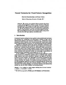
We physically emulated the leaky integrate-and-fire neuron model with a diffusive memristor, fabricated by sandwiching a dielectric material (e.g. SiOxNy or SiOx) carefully doped with Ag nanoclusters between two electrodes. This discrete device, schematically illustrated in Fig. 1a, was characterized by applying voltage pulses across the artificial neuron in series with resistors to represent synapses and recording the resulting output current versus time. Figure 1b–e compares experimentally measured data with corresponding physics-based simulation results. (See Methods.) The temporal behaviour of the artificial neuron was observed during and after the input of a single super-threshold voltage pulse followed by a train of low voltage pulses. (See Supplementary Fig. 1.) There was a distinct delay time (τd) between the arrival of the voltage pulse and the rise of the output current, which was caused by
the interaction of the RC time constant of the circuit with the internal Ag dynamics of the memristor. With a relatively large circuit capacitance, the RC time constant, that is the time for establishing the switching voltage of the diffusive memristor, dominates the delay time. (See Supplementary Fig. 2.) With a smaller capacitance, the RC time becomes shorter and the internal Ag dynamics of the memristor dominates the delay time and thus the integrate-andfire behaviour, as shown in Fig. 1. The internal Ag dynamics of diffusive memristors originates from a complicated multiphysics effect including field-induced Ag mass transport from the electrodes (e.g. Ag diffusion and redox reaction; see Supplementary Note 1.) and the formation of an electrical conducting path37–41. We have constructed a physics-based model that agrees well with the microscopic observation of Ag filament growth and rupture during
Summed presynatpic input
a
Diffusive memristor A
SiOxNy:Ag Summed neuronal inputs
Pt
b
Soma
t4
t3
Experimental
t4′
t2 t1
t3′
t2′ t1′
c
30
Experimental
200
0.5
10
150 Counts
20
Current (μA)
Voltage (V)
1.0
100 50
0.0
0 0
50
100
150
0
200
0
1
Time (μs)
1.0
0.5
0.5
I (GmaxVth)
Vex (Vth)
e 150
1.0
Simulated
1.5
Counts
d
2 3 4 5 6 Pulse number
7
8
A Simulated
100
50
0.0
0.0 0
20
40
0
1
Time (κt)
2
3
4
5
6
7
Pulse number
Fig. 1 | Diffusive memristor artificial neuron. a, Schematic illustration of a crosspoint diffusive memristor, which consists of a SiOxNy:Ag layer between two Pt electrodes. The artificial neuron receives software-summed presynaptic inputs via a pulsed voltage source and an equivalent synaptic resistor (20 µS conductance in this case). (See Supplementary Note 3 for the principle of software spatial summation.) Both the artificial and biological neurons integrate input stimuli (orange) beginning at t1 and fire when the threshold condition is reached (i.e. at t2′). The integrated signal decays over time such that input stimuli spaced too far apart will fail to reach the threshold (i.e. the delay between t3 and t4). b, Experimental response of the device to multiple subthreshold voltage pulses followed by a rest period of 200 µs (only 20 µs is shown for convenience). The device required multiple pulses to reach the threshold and ‘fire’. c, Histogram of the number of subthreshold voltage pulses required to successfully fire the artificial neuron (red) compared with a Gaussian distribution (blue). d, Simulated response of the device to multiple subthreshold voltage pulses as in b showing similar behaviour to experiment, with the resting time between pulse trains chosen to allow the Ag in the device to diffuse back to the OFF state. (Only 10% of the rest period is shown for convenience.) The time is measured in temperature relaxation time, where κ is the heat transfer coefficient (see Methods). e, Simulated switching statistics with respect to pulse numbers (within each train), consistent with the experimental results in c. The inset illustrates the circuit diagram used in the simulation. 138
Nature Electronics | VOL 1 | FEBRUARY 2018 | 137–145 | www.nature.com/natureelectronics
© 2018 Macmillan Publishers Limited, part of Springer Nature. All rights reserved.
Articles
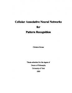
NatuRe ElectRonics threshold switching as well as the measured temporal response to voltage signals (e.g. Fig. 1 and Supplementary Fig. 1)33. Although the incorporated mechanisms of the model do not include all of the possible physics, at this stage it provides a good approximation of the rate-limiting dynamics of the diffusive memristor, and is thus sufficient for understanding the interplay between the internal Ag dynamics of the memristor and the circuit capacitance. After the fall of the voltage pulse, the memristor conductance relaxed with a characteristic time (τr) determined within our model by the Ag diffusive dynamics to dissolve the nanoparticle bridge and return the neuron to its resting state. (See Supplementary Fig. 3 for delay and relaxation properties.) The relaxation dynamics also leads to the leakiness of the internal Ag dynamics, which gradually dissolves the Ag conducting channel(s) driven by the minimization of interfacial energy between Ag and dielectrics, or Thomson–Gibbs effect33. When a sequence of sub-threshold pulses was applied to the device, as shown in Fig. 1b,d, the device fired after a certain number of pulses and relaxed back to the resting state after the end of the pulse train. Shown in Fig. 1c,e are the corresponding experimentally measured and simulated histograms of the firing statistics, respectively, which show that the threshold is not sharp but has an associated probability distribution function, providing the stochastic behaviour commonly observed in actual neurons. Since the internal memristor dynamics depend on the behaviour of nanoparticles, the leaky integrate-and-fire mechanism observed here should scale to very small device sizes. Thus, the function of the diffusive memristor in the artificial neuron is very different from that of nonvolatile drift memristors or phase-change memory devices used as long-term resistive memory elements or synapses26,42,43. The diffusive memristor integrates the presynaptic signals within a time window and transitions to a lowresistance state only if a threshold has been reached. Depending on system configurations, either the circuit RC timing or the memristor dynamics might dominate the artificial neuron temporal behaviour. For a clear demonstration of a dominant RC effect, we used a relatively large external capacitor (>1 nF) in parallel with the diffusive memristor. (See Supplementary Fig. 4.) The leaky integrate-and-fire response of the artificial neuron can be tuned by adjusting the circuit and the physical design around the device, as shown in Fig. 2a. The threshold behaviour of the diffusive memristor can be compared to that of an ion channel located near the soma of a neuron, whereas the membrane capacitance and axial resistance are represented by a capacitor Cm parallel to the memristor and a resistor Ra in series with this combination23. In a neuron, all inputs from the surrounding neurons are fed through synapses and integrated near the soma; the membrane capacitance charges up, activating the ion channels if the charge reaches the threshold, and the neuron fires. When input pulses are applied to the element shown in Fig. 2a, the circuit capacitance charges with a time constant (RaCm), increasing the voltage across the diffusive memristor. If the threshold is reached, a Ag conduction channel is formed between the electrodes, which switches the memristor and discharges (fires) the capacitor. We present data that show the capacitor charging and the subsequent firing of a current pulse by the memristor in Fig. 2b. A smaller capacitance makes the integration process and spiking faster, while a larger axial input resistance slows down the charge build-up, delaying or preventing the firing, as summarized in Fig. 2b,c. The current spike across the diffusive memristor coincides with the discharging of the capacitor, indicating the active release of the charge stored in the capacitor. Just as the physical environment of a biological neuron affects its properties44, the structure of the hybrid device and its surrounding circuit design control responses to input stimuli. This allows us to tailor the properties of the artificial neuron to achieve desirable response characteristics for specific applications. (See Supplementary Table 1 for the factors affecting firing properties.)
Interactions between artificial neurons and synapses
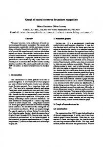
Next, we experimentally demonstrate the interactions between the artificial neurons and synapses, which serves as the basis for the learning of all biological neural systems. (See Supplementary Figs 5 and 6 for the input waveform design with RC timing effect.) A drift memristor synapse with a small weight (low conductance) is in series with the artificial neuron, consisting of a diffusive memristor in parallel with a capacitor to simulate a large circuit capacitance in this case. (See Supplementary Fig. 7a.) The synapse has a low efficiency, i.e. the voltage drop across it is large, which results in a slow build-up of charge across the circuit capacitance during the rising edge of the applied pulse. The artificial neuron integrates the input but does not fire, because it cannot reach the required threshold within the duration of this pulse. On the other hand, a synapse with a larger weight (or a higher conductance of the drift memristor synapse) results in a faster build-up of charge across the capacitance and a successful firing event, as shown in Supplementary Fig. 7b. For the case with a negligible circuit capacitance, a synapse with a small weight produces a small voltage division across the artificial neuron, which consists of a diffusive memristor in parallel with a resistor. (This parallel resistor may or may not be needed depending on the resistance ratio between synapses and neurons, see Supplementary Fig. 7c.) However, a large weight of the synapse leads to the observed firing of the artificial neuron as the voltage drop across the diffusive memristor (or the parallel resistor) becomes larger and exceeds the threshold. (See Supplementary Fig. 7d.) In order to experimentally illustrate unsupervised synaptic weight update caused by neuron firing, we used a 2 × 2 drift memristor synapse array connected to diffusive memristor artificial neurons at each output as shown in Fig. 3. All the synapses were initialized to small weights, with some variation due to the stochastic nature of their switching, as shown in Fig. 3a. We applied a triangular voltage pulse (first column in Fig. 3) or a train of rectangular spikes (third column in Fig. 3) to the first row of synapses to emulate low and high circuit capacitance, respectively. The second row is kept at nearly zero bias. The ‘10’ digital input vector pattern is used in this demonstration, but analogue inputs could be used in principle. As shown in the first and third columns of Fig. 3a,b, the neuron N2 connected to the right-hand column fires because the synapse S12 has a slightly larger initial weight. The firing of the neuron pulls down the voltage of the bottom electrodes of S12 and S22, resulting in a large voltage spike (red lines in the middle panels of Fig. 3b) across S12, further enhancing its weight. Next, we verified the network response for an input vector ‘11’. When either triangular voltage pulses (second column in Fig. 3a) or trains of rectangular spikes (fourth column in Fig. 3a), corresponding to high and low circuit capacitance, respectively, are applied to both rows of the 2 × 2 network, both neurons fire, enhancing the weights of synapses S12 and S21. (See second and fourth columns in Fig. 3b.)
Fully memristive neural networks
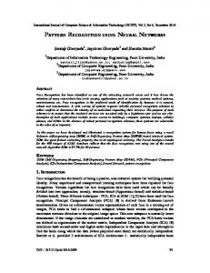
We then went a step further to demonstrate inference on a prototype fully integrated memristive neural network chip. Figure 4a shows the overview of the integrated chip consisting of a one-transistor–onememristor (1T1R) synaptic array and diffusive memristor neurons. The synapses were built by integrating drift memristors with foundry-made transistor arrays using back-end-of-the-line processes. (See Methods.) Each Pd/HfO2/Ta memristor is connected to a series n-type enhancement-mode transistor. Figure 4b shows the detailed structure of a single 1T1R cell and associated connections. When all the transistors are turned on, the 1T1R array works as a fully connected memristor crossbar. Structural analysis using highresolution transmission electron microscopy was carried out on the integrated memristors, and revealed an amorphous HfO2 layer sandwiched between Pd and Ta electrodes (Fig. 4c). Figure 4d illustrates the junction of a single diffusive memristor. A transmission
Nature Electronics | VOL 1 | FEBRUARY 2018 | 137–145 | www.nature.com/natureelectronics
© 2018 Macmillan Publishers Limited, part of Springer Nature. All rights reserved.
139
Articles
NatuRe ElectRonics
a
Ra Cm
Plasma membrane
Ion channel
b
Cm = 4.7 nF Ra = 47 kΩ
Voltage (V) Current (μA)
Cm = 10 nF Ra = 47 kΩ
4
2
2
1
0
0 40 20 0 0
c
Cm = 4.7 nF Ra = 100 kΩ
Charge (nC)
3
1 Time (ms)
0
1 Time (ms)
0
1 Time (ms)
2
30
Pulses
20
10
0
50
100
200
Pulse width (µs)
1
5 Cm (nF)
10
1
1.4
1.7
Pulse amplitude (V)
2.2 nF 5 nF 10 nF 100 kΩ 47 kΩ 22 kΩ Cm / Ra
50
200
400
Pulse interval (µs)
Fig. 2 | Controlled firing of a diffusive memristor artificial neuron. a, Illustration of an ion channel embedded in the cell membrane near the soma of a biological neuron. The inputs from the dendrites are integrated on the capacitance of the membrane and the ion channel opens if the threshold condition is reached. Also shown is the analogous electrical integrate-and-fire circuit of the artificial neuron, in which the diffusive memristor functions as the ion channel and the capacitor acts as the membrane. b, The response of the integrate-and-fire circuit to multiple consecutive pulses and the influence of varying membrane capacitance Cm and axial resistance Ra shows how the number of pulses required to charge the capacitor up to the memristor threshold increases with rising Cm or Ra. The current pulse across the diffusive memristor coincides with the discharge of the capacitor, clearly demonstrating that the device is actively firing a pulse of stored charge. c, Controlled firing response of the integrate-and-fire circuit under different input and circuit conditions. (See Methods.) A similar effect as in b can be observed by changing the input parameters such as the pulse width (shorter pulses result in a larger number of pulses before firing), pulse interval (shorter intervals result in a smaller pulse number) and circuit parameters such as capacitance (higher capacitance delays the firing). Changing the input resistance while keeping the RC constant results in a small or no change in the firing.
electron micrograph of its cross-section shows the amorphous nature of the background SiOx dielectric lattices and the nanocrystalline Ag layer in Fig. 4e. Pre-synaptic signals could be classified by such a fully memristive neural network. Here for demonstration purpose, the synapses were pre-programmed to have different weights, which could be the result of any kind of learning process. Four letter patterns, ‘U’, ‘M’, ‘A’ and ‘S’ with artificially added noise were used as example inputs. The red and blue squares in Fig. 4f represent the input differential voltages fed to the rows of the synaptic array. For example, a dark red square means a +0.8 V/−0.8 V input pair and a light blue square means a −0.6 V/+0.6 V input pair. The input pattern is divided into four sub-images of size 2 × 2, with a stride of two. Each sub-image 140
is unrolled into a single column input vector (eight voltages) and fed into the network (eight rows) at each time. For each possible subimage there is a corresponding convolutional filter implemented by eight memristor synapses in a column, with a total of eight filters (eight columns) in the 8 × 8 array. The measured weights were depicted in Fig. 4g after programming. The negative values of the convolution matrices are mapped to the conductance of memristor cells by grouping memristors from adjacent rows to form a differential pair. The results of the convolution of the eight filters to each subimage are concurrently revealed by the firing of their corresponding diffusive memristor artificial neurons, which serve the role of ReLUs. This network can produce unique response for each input pattern, as illustrated in Fig. 4h,i, in the form of integration
Nature Electronics | VOL 1 | FEBRUARY 2018 | 137–145 | www.nature.com/natureelectronics
© 2018 Macmillan Publishers Limited, part of Springer Nature. All rights reserved.
Articles
NatuRe ElectRonics a
...
...
Unit: kΩ
1
...
VNeuron 1
VNeuron 1
VNeuron 2
VNeuron 1
VNeuron 2
VNeuron 1
VNeuron 2
VNeuron 2 10
S1,1 S1,2 S2,1 S2,2
S1,1 S1,2 S2,1 S2,2
Post
S2,1 S2,2
Fire Initial
S2,1 S2,2
S1,1 S1,2
Post
S1,1 S1,2
Initial
Post
Initial
Post
Initial
Fire
INeuron 2
S2,1 S2,2
INeuron 1
S2,1 S2,2
S1,1 S1,2
Fire
INeuron 2
S2,1 S2,2
S1,1 S1,2
INeuron 1
b
S1,1 S1,2
Fire
INeuron 2
INeuron 1
INeuron 2
INeuron 1
Fire
100
Fire S1,1 S1,2
1,000
S2,1 S2,2
1.5 VPresynaptic Input 1
1.0
VPresynaptic Input 2
Voltage (V)
0.5
VNeuron 1 VNeuron 2
0.0 1.0
VS11
0.5
VS12
0.0
VS21
–0.5
VS22
–1.0
Current (μA)
800 INeuron 1 INeuron 1 Parallel Cap/Res
400
INeuron 2 INeuron 2 Parallel Cap/Res
0 0
500 Time (μs)
0
500
0
500
Time (μs)
0
Time (μs)
500
1,000
Time (μs)
Fig. 3 | Experimental demonstration of unsupervised synaptic weight update using a 2 × 2 drift memristor array interfaced with two diffusive memristor artificial neurons, illustrating circuits with high and low capacitance, respectively. a, Schematic representations of the circuits, the pre-synaptic inputs and the post-neuron outputs, and conductance maps of the synapse array before and after training, respectively. All synapses were initialized to the highresistance state with some stochastic variation before training. b, The measured presynaptic signals, the potentials across neurons and synapses, and the neural currents. Upon receiving a ‘10’ input vector, the right neuron fires with both RC (first column) and internal Ag dynamics (third column) mechanisms, which programs the synapse S12. The input vector ‘11’ results in the firing of both neurons and programs both S12 and S21 at the same time, with both RC (second column) and internal Ag dynamics (fourth column) mechanisms.
time and the maximum fire current. Supplementary Figure 8b depicts the temporal current responses of the neurons to the noisy ‘UMAS’ inputs. We have also verified the repeatability of the network by feeding the eight noise-free patterns in cycles to the network and recorded the average firing delay and current of neurons (See Supplementary Fig. 9b). Compare Fig. 4h with Supplementary Fig. 9b: the integration time of a noisy input is generally longer due to smaller inputs and thus less convolution results. Correspondingly, inputs with positive additive noise will usually fire faster. This proof-of-principle demonstration of the fully integrated memristive neural network comprising memristor-based artificial synapses and artificial neurons can be expanded to implement learning systems of higher complexity, such as multilayer neuron networks45, in an energy-efficient manner. (See Supplementary Note 2 for power consumption analysis.) Spike-timing-dependent plasticity is a prevalent protocol for synaptic weight update in spiking neural networks3,46. Here we derive a simple spike-timing-dependent plasticity scheme based on the observations in Fig. 3 to train a fully connected layer with an unsupervised approach, which naturally complements the convolution
and ReLU layers in Fig. 4 and further enables a functional convolutional network. Since the drift memristor synapses encode the conditional probability12, the neurons will tend to respond to the means of inputs associated with firing events, essentially carrying out clustering of the inputs. This is experimentally demonstrated in Fig. 5. Software pooling and signal conversion are used to convert the outputs of the ReLU layer to the inputs of the fully connected layer. (See Fig. 5a and Methods.) Lateral inhibition is deployed, which is typical in fully connected feedforward networks to enhance the discrimination of the inputs and make the self-adapting network energy efficient12,47–50. (See Methods.) After a few cycles of uncertainty, where the conductance of synapses concentrates around the initial values (~100 µS), the synapses are clearly programmed by the simple spike-timing-dependent plasticity rules. As shown in Fig. 5d, undergoing either potentiation or depression, patterns of synapses associated with the N1, N2 and N3 neurons quickly gain similarities by self-organizing processes to one of the prototypical patterns in Fig. 5a (i.e. ‘11110000’, ‘11000011’ and ‘00001100’, respectively). It is also noted that synapses may show different responses to the learning rules. For instance, the third synapse of N1 and the seventh synapse
Nature Electronics | VOL 1 | FEBRUARY 2018 | 137–145 | www.nature.com/natureelectronics
© 2018 Macmillan Publishers Limited, part of Springer Nature. All rights reserved.
141
Articles
NatuRe ElectRonics
a
b
c Ta
Synapses HfOx 10 µm
Pd
d
e
10 nm
Pt Ag SiO2: Ag
100 µm
20 µm
Neurons
Ag
10 nm
Pt
f Input patterns
Input 1
g
Input 2
Synaptic weights
Unit: µS 0
100
200 Input 3
h
Integration time Input “U”
Integration time Input “M”
Input 4
N1 N2 N3 N4 N5 N6 N7 N8
Integration time Input “A”
Integration time Input “S”
I1 I2
1,000 500
I3 I4
i
Unit: µs
0 Maximum fire current Input “U”
Maximum fire current Input “M”
Maximum fire current Input “A”
Maximum fire current Input “S”
I1 I2
Unit: mA
1 0
I3 I4 N1 N2 N3 N4 N5 N6 N7 N8 N1 N2 N3 N4 N5 N6 N7 N8 N1 N2 N3 N4 N5 N6 N7 N8 N1 N2 N3 N4 N5 N6 N7 N8
–1
Fig. 4 | Fully integrated memristive neural network for pattern classification. a, Optical micrograph of the integrated memristive neural network, consisting of an 8 × 8 1T1R memristive synapse crossbar interfacing with eight diffusive memristor artificial neurons. (Each neuron used in this demonstration has an external capacitor not shown here.) b, Scanning electron micrograph of a single 1T1R cell. Memristive synapses of the same row share bottom electrode lines while those of the same column share top electrode and transistor gate lines. c, Cross-sectional transmission electron microscopy image of the integrated Pd/HfOx/Ta drift memristor prepared by focused-ion-beam cutting. d, Scanning electron micrograph of a single diffusive memristor junction. e, High-resolution transmission electron micrograph of the cross-section of the Pt/Ag/SiOx:Ag/Ag/Pt diffusive memristor showing amorphous background SiOx with nanocrystalline thin Ag layers. f, The input pattern consists of four letters, ‘UMAS’, with artificially added noise. Each input pattern consists of 4 × 4 pixels, which are divided into four inputs (Input 1, Input 2, Input 3 and Input 4). Each input covers a sub-array of 2 × 2 size (four pixels) of the original pattern, using differential pairs as listed. Triangular voltage waveforms are fed to the eight rows of synapses of the network. g, Measured conductance weights of the memristors after programming the eight convolutional filters (one filter per column) onto the 8 × 8 array using a differential pair scheme. Each of the eight columns interfaces with a diffusive memristor neuron at the end of the column. h,i, Measured integration time and maximum amplitude of fire current of the artificial neurons as responses to the ‘UMAS’ input patterns. Each individual input pattern is associated with a unique firing pattern of the eight artificial neurons. The ideal output patterns are marked by the white dots for neurons with positive fire current flowing out of the network.
of N2 are much less potentiated, which may be due to the deviceto-device variation of threshold conditions of drift memristors. The quick divergence of conductance of drift memristors indicates a fast learning rate, which is dependent on the firing time or pulse width of diffusive memristor neurons. Such convergence is also reflected by the magnitude (or threshold) of input patterns in Fig. 5b. The magnitude of a specific pattern decreases in the first few cycles and then becomes stable. This is because diverged conductances 142
of drift memristors tend to saturate so that further increase (decrease) in conductance will become less effective when they are close to the upper (lower) bound of the conductance range.
Conclusions
We have demonstrated a stochastic leaky integrate-and-fire artificial neuron based on a discrete scalable diffusive memristor, featuring silver dynamics similar to that of actual neuron ion channels. This
Nature Electronics | VOL 1 | FEBRUARY 2018 | 137–145 | www.nature.com/natureelectronics
© 2018 Macmillan Publishers Limited, part of Springer Nature. All rights reserved.
Articles
NatuRe ElectRonics a
b
Unit: V –1.5
Pooling and signal conversion
VInput
2
INeuron
c
N1 synapses
d
4
–1
6
–0.5
8
0
N1 N2 N3
5
10
15 Cycles
20
25
30
Unit: μS 500
2 4 6
400
N2
N3
N2 synapses
8
N1
2
300
4 6
200
N3 synapses
8 2
100
4 6 8
“U/M”
“S”
“A”
Unit: mA 1 0.5 0
0 0
5
10
15 Cycles
20
25
30
Fig. 5 | Unsupervised training of a fully connected network based on the integrated all-memristive neural network. a, A schematic diagram of the 8 × 3 network with inputs based on the outputs of the neurons in Fig. 4. The prototypical patterns of neurons after training correspond to the input letters ‘U/M’, ‘S’ and ‘A’ in Fig. 4, respectively. b–d, The input patterns (peak voltages of triangular waveforms), peak neuronal currents and synaptic weights in each training cycle. The synapses of the N1, N2 and N3 neurons quickly diverge from the initial 100 µS and evolve by self-organizing processes to patterns with increasing similarities to one of the prototypical patterns in a. The magnitude of input patterns in b reduces in the first few cycles and becomes stable due to conductance saturation of the diverged drift memristor synapses.
represents the simplest, yet still faithful, realization of electronic neuronal functionality to date, and is in contrast to traditional approaches that require tens to hundreds of CMOS devices. Physics-based simulations reproduce our experimental observations and enhance our understanding of the interplay between memristor dynamics and circuit RC effects. Finally, we have shown that our artificial neurons can utilize the integrate-and-fire function to enable unsupervised synaptic weight updating and pattern classification on integrated memristive convolution neural networks.
Methods
Fabrication of discrete diffusive memristor and drift memristor. The diffusive memristor devices were fabricated on p-type (100) Si wafers with 100 nm thermal oxide. The bottom electrodes were patterned by photolithography followed by evaporation and lift-off of ~20/2 nm Pt/Ti. The approximately 16 nm thick doped dielectric layer was deposited at room temperature by reactively co-sputtering Si and Ag in Ar, N2 and O2. The approximately 30 nm Pt top electrodes were subsequently patterned by photolithography followed by evaporation and lift-off processes. Electrical contact pads of the bottom electrodes were first patterned by photolithography and then subjected to reactive ion etching with mixed CHF3 and O2 gases. The drift memristors share same substrate and bottom electrodes with diffusive memristors. The HfO2 switching layer was deposited by atomic layer deposition at 250 °C, which was subsequently patterned for reactive ion etching. Finally, top electrodes of 50/10 nm Ta/Pd were sputtered and lifted off. Fabrication of the fully integrated memristive neural network. The synapses used in the demonstration are a 1T1R array with Pd/HfO2/Ta memristors. The front-end and part of the back-end process for the transistors array was done in a commercial fab. To make a good connection between the fab metal layers and the memristors, argon plasma treatment was done to remove the native metal oxide layers followed by the deposition of 5 nm Ag and 200 nm Pd by sputtering and lift-off process, and annealing at 300 °C for 0.5 h. A 5 nm Ta adhesive layer and 60 nm Pd bottom electrodes were then deposited by sputtering and patterned by lift-off. The HfO2 switching layer was deposited by atomic layer deposition at 250 °C. The patterning of the switching layer was done by photolithography and
reactive ion etching. Top electrodes of 50 nm Ta were sputtered and lifted off. The bottom electrodes of diffusive memristors were patterned by photolithography followed by evaporation and lift-off of about 2/20/2 nm Ti/Pt/Ag. To enhance the contact between the diffusive memristor electrodes and the column wires of the drift memristors, 100 nm Pd patches were patterned, sputtered and lifted off. The approximately 10 nm thick doped dielectric layer was patterned and deposited at room temperature by co-sputtering SiO2 and Ag in Ar, followed by lift-off. The approximately 2/30 nm Ag/Pt top electrodes were subsequently patterned by photolithography followed by evaporation and lift-off processes. Electrical measurements. We used a Keysight B1530 to make the electrical measurements for the results shown in Fig. 1. Using one channel of the Keysight B1530, we applied voltage pulses across the diffusive memristor in series with a resistor and measured the current using the other channel. Electrical measurements of Figs. 2 and 3 were made using the Keysight 33622A arbitrary waveform generator, the Keysight MSOX3104 mixed signal oscilloscope and the Keysight B1530 WGFMU. Voltage pulses were applied by the Keysight 33622A. The analogue oscilloscope channels were used to measure the voltages at the output of the function generator and across the diffusive memristor. The current across the diffusive memristor was monitored using the Keysight B1530. We used electrolytic capacitors and general-purpose resistors. For the pulse width study in Fig. 2, we used a 50 kΩresistor and a 5 nF capacitor with a 100 µs pulse interval; the pulse amplitude study used 100 µs pulse ON duration and 50 µs interval with a 10 nF capacitor and a 47 kΩresistor; for the pulse interval study, we used a 50 kΩresistor and a 5 nF capacitor with a 100 µs pulse ON duration. An in-house customized measurement system was developed to operate the fully memristive neural network51. As shown in Supplementary Fig. 10a, the system works in two different modes, switched by the customized multiplexer (MUX) array. In the first mode, the row electrodes of the synaptic array (Pd electrodes of the Pd/HfOx/Ta memristors) are connected to waveform generators, which output triangular waveforms. The currents through the diffusive memristor neurons are sampled by the transimpedance amplifiers (TIAs) and microcontroller unit 2 (MCU 2). In the second mode, the rows (columns) of the drift memristor array are connected to the customized row (column) printed circuit boards, leaving diffusive memristors float. The training scheme is detailed in Supplementary Fig. 10b. The experiment runs 30 eight-pixel patterns presented to the network. Each pattern is derived from the neuron outputs in Fig. 4i. (See Supplementary Fig. 11.) Basically, input
Nature Electronics | VOL 1 | FEBRUARY 2018 | 137–145 | www.nature.com/natureelectronics
© 2018 Macmillan Publishers Limited, part of Springer Nature. All rights reserved.
143
Articles
NatuRe ElectRonics
voltages are proportional to the maximum currents of neurons in scanning one of four letters (‘U’, ‘M’, ‘A’ and ‘S’; see Fig. 4f) by software pooling. The eight-pixel outputs are generated via the four channels of the function generators by averaging each pair. (The ideal output patterns are ‘11110000’, ‘11110000’, ‘00001100’ and ‘11000011’, which allows representation in space with reduced dimensions.) The current-to-voltage conversion is done by software with added artificial noise. The lateral inhibition is realized with the training scheme and hardware assistance. The input pattern is scaled so that its maximum is 0.5 V at the beginning of each training cycle. The voltage of the input pattern gradually increases until a neuron fires. In principle, a sufficiently slow ramping rate could limit the number of concurrently fired neurons. In addition, we also program MCU 2 to float the columns of loser neurons once a fire event is identified in each cycle to assure that only the winner neuron could successfully trigger plasticity at its synapses. The depression of drift memristor synapses is done after each fire event by applying RESET pulses via the customized row boards to all drift memristors receiving low inputs of the winner neuron. Modelling the integrate-and-fire behaviour of the diffusive memristor/ capacitor. Diffusive memristor/capacitor hybrid dynamical simulations. To model the dynamics of a diffusive memristor, we consider an interplay of electric, heat and Ag-nanoparticle degrees of freedom33,52,53. Ag-nanoparticle diffusion is described by the Langevin equation: η
dx i ∂U (xi) V (t ) =− +α + 2ηkBT ζi dt L ∂xi
(1)
Here we introduce the location, xi, of the ith Ag nanoparticle, which drifts with time t in the potential landscape U (xi) under the action of the friction force ηdxi with dt particle viscosity η, the electric force α V (t) with induced charge α and distance L L between electrodes, and the random force described by the unbiased δ-correlated white noise ζi, ζi(t ) = 0, ζi(0)ζj(t ) = δi,jδ(t ). (Here δ(t ) is the Dirac delta function, and δi, j is the Kronecker delta.) The particular shape of the potential does not qualitatively change the result and should take into account the interaction attracting Ag nanoparticles to the large clusters as well as pinning of Ag nanoparticles to the inhomogeneities of the insulating matrix, resulting in a large number of smaller potential wells. The relative strength of the potential with respect to the thermal fluctuation energy kBT (with the Boltzmann constant kB and the local Ag nanoparticle temperature T, which can significantly differ from the device ambient temperature) determines the diffusion kinetics. Due to Joule heating and dissipation, the temperature T changes over time according to the Newton cooling law: dT V2 = −κ(T −T0) dt T R
(2)
where κ is the heat transfer coefficient describing heat flux from the device and T is the system heat capacity. The input power is determined by the memristor resistance R(x1, x 2, . . , x N ) and voltage V (t ) across the device. The resistance is controlled by the sequential tunnelling processes of electrons from one Ag N nanoparticle to another and can be written as R t ∑0 e (xi + 1−xi) ∕λ , where x 0 = −L and x N +1 = L are the positions of the device terminals, Rt is the resistance amplitude and λ is the tunnelling length. As a unit of resistance in our simulations we used its minimum value R min = (N + 1)R te2L ∕((N +1)λ) (occurring when all Ag nanoparticles are equally separated), while the voltage is normalized to the switching threshold value determined self-consistently as the value when the probability of switching is close to one (see Supplementary Fig. 1b). As for any distributed system with a high resistance, the diffusive memristor has an intrinsic capacitance CM. Considering the circuit shown in the inset of Fig. 1e, we derive the equation for the voltage across the memristor driven by the applied voltage Vex(t ): τ0
R dV = Vex(t )−1 + ex V R(x ) dt
(3)
where the RC time is defined as τ0 = C MR ex with the resistance Rex in series with the memristor (for simulations we used κτ0 = 0.2 and R ex = 1). R min
Data availability. The data that support the plots within this paper and other findings of this study are available from the corresponding author upon reasonable request.
Received: 11 December 2017; Accepted: 11 January 2018; Published online: 8 February 2018
References
1. Silver, D. et al. Mastering the game of Go without human knowledge. Nature 550, 354 (2017). 2. Strukov, D. B., Snider, G. S., Stewart, D. R. & Williams, R. S. The missing memristor found. Nature 453, 80–83 (2008). 144
3. Jo, S. H. et al. Nanoscale memristor device as synapse in neuromorphic systems. Nano Lett. 10, 1297–1301 (2010). 4. Yu, S., Wu, Y., Jeyasingh, R., Kuzum, D. & Wong, H. S. P. An electronic synapse device based on metal oxide resistive switching memory for neuromorphic computation. IEEE Trans. Electron Devices 58, 2729–2737 (2011). 5. Ohno, T. et al. Short-term plasticity and long-term potentiation mimicked in single inorganic synapses. Nat. Mater. 10, 591–595 (2011). 6. Pershin, Y. V. & Di Ventra, M. Neuromorphic, digital, and quantum computation with memory circuit elements. Proc. IEEE 100, 2071–2080 (2012). 7. Lim, H., Kim, I., Kim, J. S., Hwang, C. S. & Jeong, D. S. Short-term memory of TiO2-based electrochemical capacitors: empirical analysis with adoption of a sliding threshold. Nanotechnology 24, 384005 (2013). 8. Sheridan, P., Ma, W. & Lu, W. Pattern recognition with memristor networks. 2014 IEEE Int. Symp. Circuits Syst. (ISCAS) https://doi.org/10.1109/ ISCAS.2014.6865326 (2014). 9. La Barbera, S., Vuillaume, D. & Alibart, F. Filamentary switching: synaptic plasticity through device volatility. ACS Nano 9, 941–949 (2015). 10. Prezioso, M. et al. Training and operation of an integrated neuromorphic network based on metal-oxide memristors. Nature 521, 61–64 (2015). 11. Hu, S. G. et al. Associative memory realized by a reconfigurable memristive Hopfield neural network. Nat. Commun. 6, 7522 (2015). 12. Serb, A. et al. Unsupervised learning in probabilistic neural networks with multi-state metal-oxide memristive synapses. Nat. Commun. 7, 12611 (2016). 13. Park, J. et al. TiOx-based RRAM synapse with 64-levels of conductance and symmetric conductance change by adopting a hybrid pulse scheme for neuromorphic computing. IEEE Electron Device Lett. 37, 1559–1562 (2016). 14. Shulaker, M. M. et al. Three-dimensional integration of nanotechnologies for computing and data storage on a single chip. Nature 547, 74–78 (2017). 15. Suri, M. et al. Phase change memory as synapse for ultra-dense neuromorphic systems: application to complex visual pattern extraction. 2011 IEEE Int. Electron Devices Meeting https://doi.org/10.1109/IEDM.2011.6131488 (2012). 16. Eryilmaz, S. B. et al. Brain-like associative learning using a nanoscale non-volatile phase change synaptic device array. Front. Neurosci. 8, 205 (2014). 17. Burr, G. W. et al. Experimental demonstration and tolerancing of a large-scale neural network (165 000 synapses) using phase-change memory as the synaptic weight element. IEEE Trans. Electron Device 62, 3498–3507 (2015). 18. Ambrogio, S. et al. Unsupervised learning by spike timing dependent plasticity in phase change memory (PCM) synapses. Front. Neurosci. 10, 56 (2016). 19. van de Burgt, Y. et al. A non-volatile organic electrochemical device as a low-voltage artificial synapse for neuromorphic computing. Nat. Mater. 16, 414–418 (2017). 20. Indiveri, G. et al. Neuromorphic silicon neuron circuits. Front. Neurosci. 5, 73 (2011). 21. Merolla, P. A. et al. A million spiking-neuron integrated circuit with a scalable communication network and interface. Science 345, 668–673 (2014). 22. Sourikopoulos, I. et al. A 4-fJ/spike artificial neuron in 65 nm CMOS technology. Front. Neurosci. 11, 123 (2017). 23. Pickett, M. D., Medeiros-Ribeiro, G. & Williams, R. S. A scalable neuristor built with Mott memristors. Nat. Mater. 12, 114–117 (2013). 24. Lim, H. et al. Reliability of neuronal information conveyed by unreliable neuristor-based leaky integrate-and-fire neurons: a model study. Sci. Rep. 5, 9776 (2015). 25. Stoliar, P. et al. A leaky-integrate-and-fire neuron analog realized with a Mott insulator. Adv. Funct. Mater., 1604740 (2017). 26. Tuma, T., Pantazi, A., Le Gallo, M., Sebastian, A. & Eleftheriou, E. Stochastic phase-change neurons. Nat. Nanotech. 11, 693–699 (2016). 27. Al-Shedivat, M., Naous, R., Cauwenberghs, G. & Salama, K. N. Memristors empower spiking neurons with stochasticity. IEEE Trans. Emerg. Sel. Top. Circuits Syst. 5, 242–253 (2015). 28. Mehonic, A. & Kenyon, A. J. Emulating the electrical activity of the neuron using a silicon oxide RRAM cell. Front. Neurosci. 10, 57 (2016). 29. Gupta, I. et al. Real-time encoding and compression of neuronal spikes by metal-oxide memristors. Nat. Commun. 7, 12805 (2016). 30. Lim, H. et al. Relaxation oscillator-realized artificial electronic neurons, their responses, and noise. Nanoscale 8, 9629–9640 (2016). 31. Yang, Y. et al. Observation of conducting filament growth in nanoscale resistive memories. Nat. Commun. 3, 732 (2012). 32. Liu, Q. et al. Real-time observation on dynamic growth/dissolution of conductive filaments in oxide-electrolyte-based ReRAM. Adv. Mater. 24, 1844–1849 (2012). 33. Wang, Z. et al. Memristors with diffusive dynamics as synaptic emulators for neuromorphic computing. Nat. Mater. 16, 101–108 (2016). 34. Magee, J. C. Dendritic integration of excitatory synaptic input. Nat. Rev. Neurosci. 1, 181–190 (2000).
Nature Electronics | VOL 1 | FEBRUARY 2018 | 137–145 | www.nature.com/natureelectronics
© 2018 Macmillan Publishers Limited, part of Springer Nature. All rights reserved.
Articles
NatuRe ElectRonics 35. Gerstner, W. & Kistler, W. M. Spiking Neuron Models: Single Neurons, Populations, Plasticity (Cambridge University Press, 2002). 36. Hochreiter, S. & Schmidhuber, J. Long short-term memory. Neural Comput. 9, 1735–1780 (1997). 37. Tsuruoka, T. et al. Effects of moisture on the switching characteristics of oxide-based, gapless-type atomic switches. Adv. Funct. Mater. 22, 70–77 (2012). 38. Valov, I. et al. Atomically controlled electrochemical nucleation at superionic solid electrolyte surfaces. Nat. Mater. 11, 530–535 (2012). 39. Valov, I. et al. Nanobatteries in redox-based resistive switches require extension of memristor theory. Nat. Commun. 4, 1771 (2013). 40. Messerschmitt, F., Kubicek, M. & Rupp, J. L. M. How does moisture affect the physical property of memristance for anionic-electronic resistive switching memories? Adv. Funct. Mater. 25, 5117–5125 (2015). 41. Valov, I. & Lu, W. D. Nanoscale electrochemistry using dielectric thin films as solid electrolytes. Nanoscale 8, 13828–13837 (2016). 42. Wong, H.-S. P. et al. Phase change memory. Proc. IEEE 98, 2201–2227 (2010). 43. Jeyasingh, R., Liang, J., Caldwell, M. A., Kuzum, D. & Wong, H.-S. P. Phase change memory: scaling and applications. 2012 IEEE Custom Integrated Circuits Conf. https://doi.org/10.1109/CICC.2012.6330621 (2012). 44. Mainen, Z. F. & Sejnowski, T. J. Influence of dendritic structure on firing pattern in model neocortical neurons. Nature 382, 363–366 (1996). 45. Roweis, S. T. & Saul, L. K. Nonlinear dimensionality reduction by locally linear embedding. Science 290, 2323–2326 (2000). 46. Kim, S. et al. Experimental demonstration of a second-order memristor and its ability to biorealistically implement synaptic plasticity. Nano Lett. 15, 2203–2211 (2015). 47. Yu, S. et al. A low energy oxide-based electronic synaptic device for neuromorphic visual systems with tolerance to device variation. Adv. Mater. 25, 1774–1779 (2013). 48. Tuma, T., Le Gallo, M., Sebastian, A. & Eleftheriou, E. Detecting correlations using phase-change neurons and synapses. IEEE Electron Device Lett. 37, 1238–1241 (2016). 49. Pantazi, A., Wozniak, S., Tuma, T. & Eleftheriou, E. All-memristive neuromorphic computing with level-tuned neurons. Nanotechnology 27, 355205 (2016). 50. Sebastian, A. et al. Temporal correlation detection using computational phase-change memory. Nat. Commun. 8, 1115 (2017). 51. Li, C. et al. Analogue signal and image processing with large memristor crossbars. Nat. Electron. 1, 52–59 (2018).
52. Midya, R. et al. Anatomy of Ag/hafnia-based selectors with 1010 nonlinearity. Adv. Mater. 29, 1604457 (2017). 53. Jiang, H. et al. A novel true random number generator based on a stochastic diffusive memristor. Nat. Commun. 8, 882 (2017).
Acknowledgements
This work was supported in part by the US Air Force Research Laboratory (AFRL) (grant no. FA8750-15-2-0044), the Defense Advanced Research Projects Agency (DARPA) (contract no. D17PC00304), the Intelligence Advanced Research Projects Activity (IARPA) (contract no. 2014-14080800008) and the National Science Foundation (NSF) (ECCS-1253073). H.W. was supported by Beijing Advanced Innovation Center for Future Chip (ICFC) and NSFC (61674089, 61674092). The authors woule like to thank Ning Ge from HP Inc. and Mark McLean from the Laboratory for Physical Sciences at Research Park for vaulable discussions. Any opinions, findings and conclusions or recommendations expressed in this material are those of the authors and do not necessarily reflect the views of AFRL. Part of the device fabrication was conducted in the clean room of the Center for Hierarchical Manufacturing (CHM), an NSF Nanoscale Science and Engineering Center (NSEC) located at the University of Massachusetts Amherst. The authors thank Mark McLean for useful discussions on computing.
Author contributions
J.J.Y. conceived the concept. J.J.Y., Q.X., Z.W. and S.J. designed the experiments. Z.W., P.Y. and C.L. fabricated the devices. Z.W., S.J., W.S., Y.L, R.M. and M.R. made electrical measurements. S.S. carried out the simulation. S.A., Y.Z., H.J., P.L., J.H.Y., N.K.U., J.Z., M.H., J.P.S., M.B, Q.W., H.W. and R.S.W. helped with experiments and data analysis. J.J.Y., Q.X., Z.W., S.J. and R.S.W. wrote the paper. All authors discussed the results and implications and commented on the manuscript at all stages.
Competing interests
The authors declare no competing financial interests.
Additional information
Supplementary information is available for this paper at https://doi.org/10.1038/ s41928-018-0023-2. Reprints and permissions information is available at www.nature.com/reprints. Correspondence and requests for materials should be addressed to R.S.W. or Q.X. or J.J.Y. Publisher’s note: Springer Nature remains neutral with regard to jurisdictional claims in published maps and institutional affiliations.
Nature Electronics | VOL 1 | FEBRUARY 2018 | 137–145 | www.nature.com/natureelectronics
© 2018 Macmillan Publishers Limited, part of Springer Nature. All rights reserved.
145