506
IEEE TRANSACTIONS ON SYSTEMS, MAN, AND CYBERNETICS—PART C: APPLICATIONS AND REVIEWS, VOL. 34, NO. 4, NOVEMBER 2004
Fuzzy Estimation of Feed-Cutting Force From Current Measurement—A Case Study on Intelligent Tool Wear Condition Monitoring Xiaoli Li, Han-Xiong Li, Senior Member, IEEE, Xin-Ping Guan, and R. Du
Abstract—It is very important to use a reliable and inexpensive sensor to obtain useful information about manufacturing processing, such as cutting force for monitoring automated machining. In this paper, the feed-cutting force is estimated using inexpensive current sensors installed on the ac servomotor of a computerized numerical control (CNC) turning center, with the results applied to the intelligent tool wear monitoring system. The mathematical model is used to disclose the implicit dependency of feed-cutting force on feed-motor current and feed speed. Afterwards, a neurofuzzy network is used to identify the cutting force with current measurement only. This hybrid math-fuzzy approach will reduce the modeling uncertainty and measurement cost. Finally, the estimated cutting force is applied in the tool-wear monitoring process. Successful experiments demonstrate robustness and effectiveness of the suggested method in the wide range of tool-wear monitoring applications. Index Terms—Feed-cutting force, feed-motor current, fuzzy classification, monitoring, neuro-fuzzy network, tool wear.
I. INTRODUCTION
I
T IS VERY important to develop a reliable and inexpensive intelligent monitoring system for cutting processes. A successful monitoring system can effectively maintain machine tools, cutting tools and workpiece in cutting processes. Various methods have been studied to detect tool-wear states and a large variety of sensors can be used for tool-wear condition monitoring [1], [2]. Unfortunately, the performance of the monitoring system is still far behind the expectations due to its high cost/performance ratio [3] The cutting force is one of important characteristic variables to be monitored in the cutting processes. The research results show that tool breakage, tool wear, and workpiece deflection are strongly related to cutting force [4], [5]. Commercial dynamometers have been used to measure cutting force accurately. Although different types of dynamometers are available in different cutting applications, reduced stiffness of machine tools—leading to chatter and dimensional error—lack overload protection and limit their application due to high cost [6].
Manuscript received July 27, 2000; revised September 11, 2003. This work was supported by the National Natural Science Foundation of China under Grant 60274023 and by the City University of Hong Kong under Grant 7001477. This paper was recommended by Associate Editor J. Lee. X. Li and X.-P. Guan are the Institute of Electrical Engineering, Yanshan University, Qinghuangdao 066004, China (e-mail:
[email protected]). H.-X. Li is with the Department of Manufacturing Engineering, City University of Hong Kong, Hong Kong, China. R. Du is with the Department of Automation and Computer-Aided Engineering, The Chinese University of Hong Kong, Hong Kong, China. Digital Object Identifier 10.1109/TSMCC.2004.829296
In order to overcome the above disadvantages of commercial dynamometers, many researchers have used the current sensor to estimate cutting force in cutting process. Stein et al. [7] developed a dynamic lumped parameter model of the feed drive system based on dc servomotor, and studied the bandwidth, sensitivity and accuracy of current related to cutting force in turning processes. Altintas [8], [9] studied milling process monitoring with the use of current drawn by dc servo-feed-drive motors. In [10] and [11], a real-time tool breakage detection system was presented for a NC milling process by monitoring cutting force that was indirectly estimated by the feed-drive ac motor current. Modeling of the feed-drive system and calibration with a tool dynamometer showed that the sensitivity of the feed-drive motor current was sufficient to characterize the tool breakage. Chang [12] proposed a neural network to construct a model of the spindle system, estimated the cutting force and detected the chatter of CNC machine tools by measuring the voltage and the current of the spindle motor. Recently, Haber et al. [13] developed an indirect cutting force controller using fuzzy techniques and an ac transformer current sensor located in the spindle motor that provides the cutting force signals for the end milling process. In summary, the current sensor is less expensive, more durable and flexible, and also very simple to install. Using the motor current to estimate the cutting force, the cutting force-based monitoring system should be fully developed. Though many research results have been presented in cutting force estimation using motor current measurement, few are applied in the turning process with ac servo feed-drive system. Furthermore, many of the presented research use a linear mathematical model to approximate the system. In this paper, the feed-cutting force estimation will be presented using the current from ac servo motor, and applied to monitor the tool wear in turning. The feed-cutting force measurement with a current sensor in the feed motor is set up on the CNC turning center. The mathematical model of the feed-drive system is developed to disclose the implicit dependency of feed-cutting force on feed motor current and feed speed. Then, a neuro-fuzzy network can be used to identify the cutting force with the motor current and the feed speed. To reduce the modeling uncertainty and cost of measurement, a simple mathematical equation is explored to model the linear relationship between the frequency of feed-drive current and the feed-drive speed. Based on this hybrid mathematical-fuzzy approach, the feed-cutting force can be easily estimated from current measurement only. A fuzzy classification method is presented to model the relationship between
1094-6977/04$20.00 © 2004 IEEE
LI et al.: FUZZY ESTIMATION OF FEED-CUTTING FORCE FROM CURRENT MEASUREMENT
507
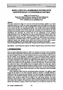
Fig. 2. Relationship between the feed speed and the air-cutting current on the CNC turning center.
Fig. 1.
where is motor constant of the feed motor; , is the air-cutting current, and is the cutting current. Since the actual feed force is related to the cutting torque as shown in (3), the estimation of cutting torque can be achieved by measurement of the cutting current
Ac servo feed-drive system.
the estimated feed-cutting force and the tool-wear states under different cutting conditions. The experimental results show that this hybrid approach can provide a robust performance, and can be easily applied to monitor tool wear in turning. The real experiment exposes a promising future of the suggested approach in industrial applications. The advantage of the monitoring system for feed-cutting force is that it only requires low cost sensors (current sensor) and little additional hardware. All required are simple data acquisition, filter, data processing, and neuro-fuzzy model. II. SENSING SYSTEM FOR FEED-CUTTING FORCE A. Feed-Cutting Force Modeling The typical ac servo feed system on the CNC lathe consists of the following basic components: tool, tool post, slide, bearings, ball screw, feed box, feed motor, and lubrication system, as illustrated in Fig. 1. In the cutting processing, the motor torque, which is proportional to the armature current, , is used to accelerate the equivalent feed-drive inertia, and overcome the viscous damping, friction in the drives, and cutting torque on the motor shaft [7]
(3) where is the feed-cutting force, is the ball screw efficiency, is the pitch of the ball screw, and is the radius of the ball screw. From the above equations, the feed-cutting force is closely related to cutting current and cutting speed, and it is possible to estimate the feed-cutting force by using the measured motor current and feed speed. It is known that the current consumed by the feed-cutting force is only one part of the can be estimated total motor current. The air-cutting current , called the cutvia (6). The remaining current ting current, is caused by the cutting force, which is actually the additional friction from the cutting load and damping of the . On the other hand, the damping of the feed-drive system feed-drive system depends on the feed speed. Therefore, the estimation of the feed-cutting force is a function of both the cutting current and the feed speed , which can be expressed as in (4) B. The Air-Cutting Current
(1) where is motor constant of the feed motor, is the inertia of the motor armature, feed box, ball screw, and slide together, is the viscous damping of the feed box, bearings, ball screw, and is the dry or Coulomb friction of the slide and other slide, components, and is the torque induced by feed-cutting force. In a steady-state period, it can be assumed that , then the monitoring model of feed-drive system can be described as follows [5]: (2)
In order to estimate the cutting force with the measured , consumed by the cutting torque current, the cutting current, has to be separated from the total motor current, . The practical experiment on a CNC turning center (Type: HITEC TURN 20SII) shows that the relationship between air-cutting current, , and the feed speed (see Fig. 2) is approximately linear and can be approximated by (5) where is feed speed (mm/min), and parameters and are variables need to be identified. The least-squares method can be
508
IEEE TRANSACTIONS ON SYSTEMS, MAN, AND CYBERNETICS—PART C: APPLICATIONS AND REVIEWS, VOL. 34, NO. 4, NOVEMBER 2004
Fig. 3. Linear relationship between the feed speed and the frequency of current signals on the CNC turning center.
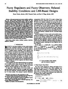
Fig. 4. The relationship between feed-cutting force and cutting current on the CNC turning center.
(1I )
used for the parameter identification. The estimated results are shown in (6) at a 95% confidence level (6) C. The Feed Speed Feed speed is closely related to the friction and viscous damping of machine tools. According to Fig. 2, different feed speed results in different air-cutting current. Therefore, to obtain feed speed is very important for estimating the feed-cutting force. The practical measurement on a CNC turning center (see Fig. 3) shows that the frequency of cutting current signal is linear to the feed speed as described in (7) at 99.5% confidence level (7) Therefore, the feed speed can be estimated with the frequency of the cutting current signal. D. Estimation of Feed-Cutting Force via Neuro-Fuzzy Approach It is essential to understand the relationship of the feed-cutting force with the feed-cutting current and feed speed. A 3-component dynamometer (cutting force sensor, type Kister 9255B) and a current sensor (Hall Effect Current Transducers, Stock no. 286-327) are used to measure feed-cutting force and feed-motor current, respectively. The practical measurement on a CNC turning center (see Fig. 4) shows that the feed-cutting force increases nonlinearly with the cutting current under the steady cutting states. In this paper, an adaptive neuro-fuzzy inference system (ANFIS) [16] will be used to estimate the feed-cutting force by using the feed-cutting current and the feed speed, as shown in (4). ANFIS is actually a four-layer neural network that simulates the working principle of a fuzzy inference system. The weights of the network are tuned using the back-propagation algorithm based on the collection of input-output data.
Fig. 5. ANFIS structure for estimation of the feed-cutting force.
The suggested ANFIS model for force estimation is shown and the in Fig. 5. Two feature variables, the cutting current feed speed , are selected as inputs of the ANFIS. The linguistic nodes in layer one and four represent the input and output linguistic variables, respectively. Five membership functions (MFs) are signed to each linguistic variable respectively, which are handled by nodes in layer two. Each neuron of the third layer represents one fuzzy rule, with input connections representing preconditions of the rule and the output connection representing consequences of rules. Initially, all of these layers are fully connected, representing all possible rules. The estimation of feed-cutting force can be summarized with the operation framework in Fig. 6. The feed-motor current is measured using PCB Mounting Hall Effect Current Transducers (Stock no. 286-327). The root mean square (RMS) of the current signal which passes a low-pass (500 Hz ) filter can be obtained. The feed speed can be calculated via (7), and the air-cutting current via (6). Finally, the feed-cutting force can be estimated using the ANFIS with the feed-cutting current and feed speed as two inputs. III. INTELLIGENT TOOL-WEAR CONDITION MONITORING After the feed-cutting force was estimated by the above method, then the estimated feed-cutting force will be applied to monitor tool-wear condition. Herein, a fuzzy classification method is presented to describe the relationship between the
LI et al.: FUZZY ESTIMATION OF FEED-CUTTING FORCE FROM CURRENT MEASUREMENT
509
Fig. 6. Operation framework for estimating feed-cutting force. TABLE I CLASSIFICATIONS OF TOOL WEAR
estimated feed-cutting force and the tool-wear states under different cutting conditions; then the estimated feed-cutting force can be directly applied to monitor the tool-wear condition in turning.
TABLE II CUTTING CONDITIONS FOR TOOL-WEAR MODEL
A. Modeling (m/s), The feed-cutting force is related to cutting speed feed rate (mm/rev), depth of cut (mm), and tool wear (mm) as well. The variables , , , and are assumed to be known or determined before the operation. According to the practical requirement, the tool-wear condition can be classified is into six groups, as in Table I [14]. The feed-cutting force the function of all these variables under certain tool-wear classification based on the experiential model of cutting force, as shown in the following: (8) is a constant with the tool geometry and workpiece where material, parameters , and are exponents of cutting variand ( is the spindle speed ables, (rpm), is the diameter of workpiece (mm), and is the feed speed (mm/min)]. Taking logarithm of (8), the relationship between the cutting-force and tool wear can be obtained in (9) for six different tool-wear classifications, as follows:
(9)
where , , with subscripts denoting the respective wear states.
The operation procedure consists of two steps. First, the matrix on the right side needs to be determined via a series of off-line experiments. After choosing different values for varican be comables , , and , a set of relevant force . Its relevant paputed for each wear state rameters , and could thus be derived through the traditional least-square estimation method, so that all parameters on the right side of (9) become known. Then, (9) can be used to (via ) on-line after secalculate the cutting force lecting the variables , , and . The modeling of the cutting force is successfully achieved. A total of 60 tool-wear cutting tests are collected under the various cutting condition, as shown in Table II. According to the classification of the tool-wear states, the samples are divided into six groups. The parameters in (9) , , , and can be calculated by the least-square method, and the results are shown as follows:
510
IEEE TRANSACTIONS ON SYSTEMS, MAN, AND CYBERNETICS—PART C: APPLICATIONS AND REVIEWS, VOL. 34, NO. 4, NOVEMBER 2004
Fig. 7. Fuzzy inference system for tool-wear classification.
Fig. 10.
Fig. 8. MFs of the input variable f = ln(F ).
The comparisons of the actual and the estimated feed-cutting force.
A defuzzification is required to obtain the crisp output after fuzzy inference. The most commonly used method is the center of gravity (COG) method [15]. IV. EXPERIMENTS AND RESULTS
Fig. 9.
MFs of the output variable tool wear.
The correlation coefficients corresponding to the weight value of each group are 0.89, 0.92 0.981, 0.979, and 0.984. It is obvious that the correlation coefficients are very close to unity, that indicates the relationship between the cutting force and cutting parameters is well represented by the proposed model. B. Fuzzy Classification of Tool-Wear Conditions and the tool The mapping between the feed-cutting force wear is nonlinear, and can be implemented with a fuzzy inference system as shown in Fig. 7. The input variable is the con, which will be fuzzified before the inverted force are ference. Since the six force parameters defined as cluster centers of different tool-wear classification, standard triangular MFs can be used to describe the input variable as shown in Fig. 8. For convenience, six labels are named to match the definition in Table I. Another important step is to choose proper MFs for the output variable based on experimental results. The output of the fuzzy system is the tool wear, whose MFs can be characterized according to the wear classification data in Table I and as shown in Fig. 9. From the experiments, six fuzzy inference rules can be easily derived in the following format:
To compare the estimated results and the actual measurement, cutting tests were carried out on the CNC turning center. The actual cutting force was measured by a Kistler cutting force dynamometer, and compared with the estimated one obtained via the procedure in Fig. 6. The comparisons were made under different cutting conditions, as shown in Fig. 10. The error between the actual and the estimated ones is within 5%, which validates the accuracy and the feasibility of the suggested approach. In order to test the monitoring strategy of tool-wear condition, a set of cutting tests is carried out under various cutting conditions. Forty samples are randomly chosen for learning, and 19 of them are used as the test samples in the classification phase. For verifying the reliability of the above method, actual tool-wear values are compared with the estimated values. This comparison, given in Fig. 11, shows the accurate estimation for tool-wear states, which validates the effectiveness of the suggested method in practice. The algorithm is ease of implementation and reliable in operation, and can be applied without extra cost. Furthermore, not only can the method fit with feed-cutting force signal, but also can fit with other signals, etc. Therefore, the suggested method is worth to be developed for other tool condition monitoring system. V. CONCLUSIONS The tool-wear monitoring system is an effective way to prevent machine tools, cutting tools and workpiece from damage in manufacturing processes. If the cost-performance ratio of the monitoring system is too high, it may not be acceptable for the application in industry. In this paper, a hybrid mathematical-fuzzy approach has been presented for estimation of feed-cutting force from the feed motor
LI et al.: FUZZY ESTIMATION OF FEED-CUTTING FORCE FROM CURRENT MEASUREMENT
Fig. 11.
Comparisons of actual and estimated tool wear. Workpiece: 45
511
steel; tool nose radius r = 0:8 mm.
current. Then the estimated feed-cutting force is used to monitor tool-wear condition based on fuzzy reasoning. The contributions of the proposal can be summarized as follows.
• The accuracy of feed-cutting force estimation has reached 95%, and meets the need of the monitoring cutting process.
512
IEEE TRANSACTIONS ON SYSTEMS, MAN, AND CYBERNETICS—PART C: APPLICATIONS AND REVIEWS, VOL. 34, NO. 4, NOVEMBER 2004
• The measurement apparatus do not disturb the machining process, and the cost-performance ratio is very low. This hybrid monitoring approach has been experimentally verified on a CNC turning center. The practical experiment confirms that the suggested approach has ease of implementation, and is reliable in operation as well.
ACKNOWLEDGMENT The authors would like to thank the referees and technical editor for helpful comments to improve this paper.
REFERENCES [1] D. Li and J. Mathew, “Tool wear and failure monitoring techniques for turning—a review,” Int. J. Mach. Tools and Manufact., vol. 30, no. 4, pp. 579–598, 1990. [2] L. K. Daneshmand and H. A. Pak, “Performance monitoring of a computer numerically controlled (CNC) lathe using pattern recognition techniques,” presented at the 3rd Int. Conf. Robot Vision and Sensor Controls, Cambridge, MA, Nov. 1993, pp. 6–10. [3] J. L. Stein and K. Huh, A design procedure for model-based monitoring systems: cutting force estimation as a case study, in Control of Manufacturing Processes, ASME, pp. 45–57, 1991. [4] J. Tlusty and G. C. Andrews, “A critical review of sensors for unmanned machining,” Ann. CIRP, vol. 32, no. 2, pp. 611–622, 1983. [5] M. Weck, “Machine diagnostics in automated production,” J. Manufact. Syst., vol. 2, no. 2, pp. 101–106, 1983. [6] G. Byrne, D. Dornfled, I. Inasaki, G. Ketteler, W. Konig, and R. Teti, “Tool condition monitoring (TCM)—the statue of research and industrial application,” Ann. CIRP, vol. 44, no. 2, pp. 541–567, 1995. [7] J. L. Stein, D. Colvin, G. Clever, and C.-H. Wang, “Evaluation of dc servo machine tool feed drives as force sensors,” J. Dynamic Syst., Measurement & Control, Trans. ASME, vol. 108, no. 4, pp. 279–288, 1986. [8] Y. Altintas and C. L. Dong, “Design and analysis of a modular CNC system for machining control and monitoring,” in Modeling of Machine Tools: Accuracy, Dynamics, and Control American Society of Mechanical Engineers, Production Engineering Division (Publication) PED. New York: ASME, vol. 45, pp. 199–208. [9] Y. Altintas, “Prediction of cutting forces and tool breakage in milling from feed drive current measurements,” J. Eng. Industry—Trans. ASME, vol. 114, no. 4, pp. 386–392, 1992. [10] J. M. Lee, D. K. Choi, J. Kim, and C. N. Chu, “Real-time tool breakage monitoring for NC milling process,” Ann. CIRP, vol. 44, no. 1, pp. 59–62, 1995. [11] T. Y. Kim and J. Kim, “Adaptive cutting force control for a machining center by using indirect cutting force measurements,” Int. J. Machine Tools and Manufact., vol. 36, no. 8, pp. 925–937, 1996. [12] Y. C. Chang, K. T. Lee, and H. Y. Chuang, “Cutting force estimation of spindle motor,” J. Control Syst. Technol., vol. 3, no. 2, pp. 145–152, 1995. [13] R. Haber, C. Peres, R. Clodeinir, A. Alique, S. Ros, C. Gonzalez, and J. R. Alique, “Toward intelligent machining: hierarchical fuzzy control for the end milling process,” IEEE Trans. Control Syst. Technol., vol. 6, no. 2, pp. 188–199, 1998. [14] X. Li, X. Guan, and H. Wang, “Identification of tool wear states with fuzzy classification,” Int. J. Comput. Integrated Manufact., vol. 12, no. 6, pp. 503–509, 1999. [15] C. C. Lee, “Fuzzy logic in control systems fuzzy logic controller—Part II,” IEEE Trans. Syst., Man, Cybern., vol. 20, pp. 419–435, 1990. [16] J. S. R. Jang, “Adaptive-network-based fuzzy inference system,” IEEE Trans. Syst., Man, Cybern., vol. 23, no. 3, pp. 665–684, 1993.
Xiaoli Li received the B.S.E. and M.S.E. degrees from Kun-ming University of Science and Technology, Kun-ming, China, and the Ph.D degree from Harbin Institute of Technology, Harbin, China, in 1992, 1995, and 1997, respectively, all in mechanical engineering. From April 1998 to October 2000, he was a Research Fellow with the Department of Manufacturing Engineering, City University of Hong Kong. From November 2000 to November 2002, he was a Research Fellow of the Alexander von Humboldt Foundation at the Institute for Production Engineering and Machine Tools, Hannover University, Hannover, Germany. Currently, he is a postdoctorate Fellow at the Department of Automation and Computer-Aided Engineering, Chinese University of Hong Kong. His main areas of research include computation intelligence, signal processing and data analysis, monitoring, bio-signal analysis (EEG), and manufacturing systems.
Han-Xiong Li (SM’00) received the B.E. degree from the National University of Defence Technology of China in 1982, the M.E. degree in electrical engineering from Delft University of Technology, The Netherlands, in 1991, and the Ph.D. degree in electrical engineering from the University of Auckland, Auckland, New Zealand, in January 1997. Currently, he is an Associate Professor in the Department of Manufacturing Engineering and Engineering Management, City University of Hong Kong. In last 20 years, he has had the opportunity to work in different fields, including military intelligence service, finance, industry, and academia. His research interests include intelligent control, and industrial process control with emphasis on semiconductor packaging. Dr. Li serves as an Associate Editor for the IEEE TRANSACTIONS ON SYSTEMS, MAN, AND CYBERNETICS—PART B.
Xin-Ping Guan received the B.S. degree in mathematics from Harbin Normal University, Harbin, China, the M.S. degree in applied mathematics, and the Ph.D. degree in electrical engineering, both from Harbin Institute of Technology, Harbin, China, in 1986, 1991, and 1999, respectively. He is currently a Professor and Dean of the Institute of Electrical Engineering, Yanshan University, Qinhuangdao, China. He has published more than 120 papers in mathematical, technical journals and conferences. As a (co)-investigator, he has finished more than 17 projects supported by National Natural Science Foundation of China (NSFC), the National Education Committee Foundation of China, and others. His research interests include functional differential and difference equations, robust control and intelligent control of time-delay systems, chaos control, and synchronization and congestion control of networks. Dr. Guan is a Reviewer of Mathematic Review of America, a member of the Council of the Chinese Automation Committee and a member of the Council of the Chinese Artificial Intelligence Committee.
R. Du was born in China in 1955. He received the Master’s degree from South China University of Technology in 1983 and the Ph.D. degree from the University of Michigan, Ann Arbor, in 1989. He has held teaching positions at the University of Windsor, Windsor, ON, Canada, and at the University of Miami, Coral Gables, FL. Currently, he is a Professor in the Department of Automation and Computer-Aided Engineering, Chinese University of Hong Kong. His areas of research include condition monitoring and fault diagnosis, and manufacturing processes (metal forming, machining, plastic injection molding, etc.).