INTERNATIONAL JOURNAL of RENEWABLE ENERGY RESEARCH S.Ghosh et al., Vol. 5, No. 3, 2015
Bio- gasification Based Distributed Power Generation System Employing Indirectly Heated GT and Supercritical ORC: Energetic and Exergetic Performance Assessment P. Mondal*, K Mondal*, S. Ghosh*‡ *Department of Mechanical Engineering, IIEST, Shibpur, W. B.-711103, India (
[email protected],
[email protected],
[email protected])
‡ Corresponding Author; S. Ghosh, Department of Mechanical Engineering, IIEST, Shibpur, W. B.-711103, India, Tel: + 91 33 2668 4561/62/63 Ext 279 Fax: + 91 33 2668 2916,
[email protected] Received: 17.04.2015 Accepted:04.06.2015 Abstract-Biomass based distributed power generation has immense possibilities due to availability and CO2 neutrality of biomass feeds. In community scale distributed generation systems, conventionally biomass gasifier - gas engine is employed. Such systems offer low overall efficiency (about 20-25%) and require elaborate gas cleaning and gas cooling arrangements. These shortcomings of conventional systems can be overcome by employing an indirectly heated gas turbine cycle along with a coupled Rankine cycle. This paper presents thermodynamic model of a novel biomass gasification based combined cycle plant consisting of an indirectly heated gas turbine (GT) block as topping cycle and a supercritical organic rankine cycle (ORC) block as bottoming cycle. A typical Indian solid biomass viz. saw dust is considered as the fuel feed which undergoes gasification in a downdraft gasifier and the producer gas is combusted in a combustor-heat exchanger duplex (CHX) unit. The CHX unit heats up air for a 30 kWe Gas Turbine (GT) and the exhaust of CHX unit is utilized by the bottoming ORC, where toluene is the working fluid. The simulated performance of the plant is assessed over a wide ranges pressure ratio (r p) and turbine inlet temperature (TIT) for the GT block. rp value varying from 4-16 and TIT value 900-1100 deg C. For the base case configuration (rp= 4 and TIT=1000 deg C) the plant gives an overall electrical efficiency of above 45%. The efficiency is found to maximize at a particular value of topping cycle pressure ratio, depending on TIT, optimum r p being higher at higher TITs. The study also includes discussion on the sizing of the major plant components. Further, a Second law analysis of the plant concludes that maximum exergy destruction takes place at the gasifier, followed by the CHX unit, together accounting for nearly 40% of the fuel exergy. Keywords: Biomass gasification, Indirectly heated, Gas turbine, Supercritical-ORC, Energy, Exergy. 1. Introduction Worlds‟ fastest growing form of delivered energy i.e. electricity generation is anticipated to increase at an annual rate of 3.6 percent during 2013-2040 period, with 25 percent of total electricity coming from renewable sources [1]. However, 80 percent of the renewable energy contribution comes from hydropower and wind energy, although they are site-specific and dependent on the natural activity [1, 2]. Biomass based power generation is getting increased worldwide importance in overcoming the energy scarcity problems and environmental issues. Energy from biomass is efficiently recovered through its gasification in oxygen starved condition [3]. Wide range of biomass gasifier-gas engine assemblies is commercially available for decentralized electricity production, although these systems suffers from low overall efficiency (~20-25 percent) and extensive gas cleaning and cooling requirements [4].
gasification. These integrated systems offer substantial improvement in efficiency [5]. However, the major problems with these systems are the extreme gas cleaning and cooling requirements as the gas turbine blades are very sensitive to the presence of tar, particulate matter, dust particles and moisture in the producer gas [6]. The dirty producer gas may leads in erosion, corrosion and particulate deposition problems in the gas turbine bladding and may block the fuel injectors. Modification of the combustor is also essential for using producer gas in conventional gas turbine because of its lower calorific value [6, 7]. Worlds‟ first bio-gasification based combined cycle power plant was operated during 1996 in Varnamo, Sweden with an overall efficiency of 32 percent. The operation of the plant was stopped due to high operation and maintenance cost [8] as extensive gas cleaning and cooling were required for the combustor and gas turbine.
Bio-energy can efficiently be utilized by integrating gas turbine (GT)-steam turbine (ST) combined cycle with bio-
The gas cleaning and cooling complexities along with the modification requirements of combustor and rotor balding
INTERNATIONAL JOURNAL of RENEWABLE ENERGY RESEARCH S.Ghosh et al., Vol. 5, No. 3, 2015 can be overcome by implementing bio-gasification based indirectly heated combined cycle plant as the fuel is combusted in an external combustor [9]. A heat exchanger is mounted immediately after the combustor which heats up the working fluid of the topping GT cycle. The combustor and heat exchanger used in topping GT cycle is together called a combustor-heat exchanger duplex (CHX) unit [9, 10]. Different configurations of the bottoming cycle have been proposed to recover the exhaust heat of the topping cycle. GT-ST based combined cycle offers overall efficiency of about 40 percent [7, 9, 10, 11]. In recent years researchers have been paying attention towards the development of biomass fired organic Rankine cycle (ORC). These systems are capable of producing an electrical efficiency range of 16-24% depending upon the mode of operation of the cycle, whether subcritical and supercrictical and also on the working fluids [12, 13]. The efficiency level may reach a level of about 50% when ORC is used as bottoming cycle of a combined cycle plant and toluene as working fluid [14]. In this paper, toluene based ORC as bottoming cycle and operating in supercritical mode is integrated to recover the exhaust heat of a topping biogasification based indirectly heated GT cycle.
Thermodynamic modelling of such integrated plant and its simulated performance is assessed over a wide range pressure ratio (4 to 16) and turbine inlet temperature (900 to 1100 deg C) for the GT block. Exergetic performance of the plant components, identifying the major exergy destroying components and their exergetic efficiency are also reported in this paper. The study also discusses the sizing of the major plant components. Thermal modelling and performance assessment have been carried out using Cycle-Tempo software [15]. 2.
Proposed Plant Configuration
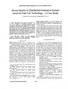
Fig. 1 shows the schematic diagram of the conceptualized biomass based combined cycle plant employing indirectly heated gas turbine (GT) and supercritical organic rankine cycle (ORC). Solid biomass (saw dust) is fed to a downdraft gasifier (block 4) to convert it into producer gas, in the presence of sub-stoichiometric condition of atmospheric air supply. The hot producer gas enters the combustion chamber (block 5) and gets combusted in the presence of recirculated GT exhaust air. Flue gas, generated during the combustion process, enters the shell side of a high pressure high
, Fig. 1. Schematic of the proposed plant
774
INTERNATIONAL JOURNAL of RENEWABLE ENERGY RESEARCH S.Ghosh et al., Vol. 5, No. 3, 2015 temperature (tube side) air heater (block 6). Block 5 and block 6 together called as combustor-heat exchanger duplex (CHX) unit, heats up the working medium (air) of the topping GT cycle. Atmospheric air after passing through the compressor (block 7) enters the CHX unit and gets heated up. The hot and compressed air then expands in the gas turbine (block 8) to atmospheric pressure and enters the combustion chamber of the CHX unit and thus combustion takes place. The exhaust of CHX unit enters the ORC-superheater (block 9) and produces supercritical organic vapor for the organic turbine (ST-block 14). An electric generator is coupled with the gas turbine rotor to produce electricity. The exhaust of ORC-vapor turbine enters an internal recuperator (block-10) which preheats the organic fluid entering the heat recovery unit (block 9). Finally, the ORC-T exhaust enters the condenser (block 13), followed by the feed pump (block-12). The pumped fluid enters the internal recuperator, gets preheated and enters the ORC-superheater and thus the bottoming cycle continues.
No pressure loss occurs in the gas path, air path and in the ORC path. The bottoming cycle consists of internal recuperator based supercritical organic Rankine cycle operating at 46 bar and 3400C. The condenser pressure is 0.7 bar. The isentropic efficiencies of air compressor and GT are 90%, while the same for bottoming ORC-T is 85%. Stack temperature is 1200C. 3.1.1 Gasification Unit The dry biomass feedstock can be expressed by the generalized molecular formulae CHPOQNR. The subscripts P, Q and R are determined using the ultimate analysis of biomass, presented in “Table 1”. Table 1. Ultimate analysis of fuel used [2]. Composition C H N O Ash
Mass Percentage on Dry Basis (%) 52.28 5.2 0.47 40.85 1.2
The ORC-superheater along with ORC-turbine, condenser, feed pump and internal recuperator constitutes the bottoming organic rankine cycle where toluene is the working fluid. The cycle operates on supercritical mode. The pump is driven by an electric motor (block 11). The final exhaust from the plant is exposed to atmosphere through stack (block 15).
as:
3.
CH P OQ N R + wH 2 O + X0 (O2 + 3.76N 2 )
Model Development and Mathematical Formulation
The model development and thermal performance assessment have been carried out using Cycle-Tempo software. In Cycle-Tempo, different components models are available in the component library from which necessary components can be picked and connected to represent a process or a cycle. Thermodynamic First Law and Second Law analyses have been carried out for the plant by varying certain design and performance parameters. The following sections describe the assumptions and applicable thermodynamic relations for the relevant processes and components. 3.1. First Law Analysis The following assumptions are made for the analysis: The biomass gasifier is fixed bed downdraft type and chemical equilibrium model is considered. Saw dust is the biomass feed. Its ultimate analysis of biomass is presented in Table 1. Chemically the biomass species is represented by CH0.59O0.29N0.0038.Its lower heating value of saw dust is 16421.4 kJ/kg. Moisture content is 16 %. The equivalence ratio for the gasification is 0.35 and the reaction temperature is 6800C. Tar formation is negligible and not considered here. 5% unconverted carbon appears as char loss is assumed in the gasifier. Ash is represented by SiO2 for this model [16].
The generalized global gasification reaction is presented
X1H 2 + X 2 CO + X3CO2 + X 4 H 2 O +
(1)
X5CH 4 + X6 N 2 Where X1, X2, X3, X4, X5 and X6 are the number of moles of the respective gas species. X0 is the moles of O2 in gasification air and w is the moisture associated with every mole of the biomass. The producer gas temperature and gas composition are calculated from the elemental mass balance, reaction equilibrium for methanation and shift reactions (Eq. 1) as well as overall energy balance (Eq. 2). The product gas composition and gasifier outlet temperature are also dependent on the “equivalence ratio” of the gasifier. The equilibrium constants of the said equations are dependent on the gasification temperature (Tgasi) [3, 16].
CO + H 2 O CO2 + H 2
(2)
C + 2H 2 CH 4
The efficiency of the gasification process is calculated as follows:
ηgasi =
mp.g LHVp.g mb LHVb
(3)
3.1.2 Indirectly heated Gas turbine (IHGT) Unit Compressor (block 9) work requirement per mol of admitted air is expressed as:
No extraneous heat loss occurs in the plant components and in the ducts.
775
INTERNATIONAL JOURNAL of RENEWABLE ENERGY RESEARCH S.Ghosh et al., Vol. 5, No. 3, 2015
w C = cp,air (Tc,o - Tc,i )
(4)
Xm
m
Where, compressor outlet temperature (Tc,o) is calculated using the compressor pressure ratio (rp) and isentropic efficiency of the compressor. Gas turbine (block 10) work output per mol of admitted air is expressed as: (5)
w GT = cp,air (TGT,i - TGT,o )
Where, turbine outlet temperature (T GT,o) is calculated using the turbine pressure ratio (rp) and isentropic efficiency of the turbine.
= Xfg = X7 + X8 + X9 + (X6 + 3.76X0' )
(9)
3.1.4 Organic Rankine Cycle (ORC) Unit The exhaust of the CHX unit is recovered through the supercritical organic rankine cycle using an ORCsuperheater. Working fluid for the bottoming cycle is considered to be toluene and the bottoming cycle operates in supercritical mode. Thermo-physical properties of toluene are shown in Table 2. Table 2. Properties of toluene [14] Parameter
Unit
Value
3.1.3 Combustor-Heat Exchanger Duplex (CHX) Unit
Molecular Formulae ---C7H8 Molecular Weight kg/kmol 92 Hot producer gas gets combusted in the combustion o chamber of the CHX unit (block 7), in the presence of Critical Temperature C 318.65 recirculated GT exhaust air. The combustion equation can be Critical Pressure bar 41.06 represented as follows: o Boiling Point C 110.7 ' X1H2 + X2 CO + X3CO2 + X4 H2 O + X5CH4 + X6 N2 X 0 (O2 + 3.76N2 ) X7 CO2 + X8 H2 O The supercritical organic vapor generation rate is given ' by: + X O 9 2 + (X6 + 3.76X 0 )N 2 ' + X5CH + X6 N2 X 0 (O2 + 3.76N2 ) X7 CO2 + X8 H2 O ' 4 (10) Xfg cp,fg (TCHX,o - TStack,i ) = XOShSUP (6) 2 X 0 (O2 + 3.76N 2 ) X7 CO2 + X8 H 2 O + X9 O' 2 + (X6 + 3.76X'0 )N2 + X9 O2 + (X6 + 3.76X 0 )N 2 Where, XOS denotes the number of moles of organic vapor entering the ORC-T. The ORC-T electrical output is Where X7, X8 and X9 are the number of moles of CO2, H2O expressed as: and O present in the flue gas X ' denotes mol of O entering
,o
2
0
2
the combustion chamber. The post combustion temperature is calculated using energy balance equation of the streams and considering the adiabatic condition as: o
X j (h fj j
Tpc
+
TGasi,o
o cp j ΔT)pg + Xk (h fk + k
k
Tpc
TGT,o
o cp,air ΔT)air = Xm (h fm + m
o cp j ΔT)pg + Xk (h fk +
Tpc
TGT,o
cp,air ΔT)air
o cp,air ΔT)air = Xm (h fm +
Tpc
TGasi,o
m
Tpc
TGasi,o
WORC-ST = XOS (h ORCT,i - h ORCT,o )ηG
(11)
Temperature-entropy diagram of the combined cycle plant is shown in Fig. 2. The feed pump is driven by an Tpc o electromotor through external power source and pump work = Xm (h fm + cfm ΔT)fg m is Tneglected. Gasi,o
cfm ΔT)fg (7)
Network output from the topping cycle is expressed as:
Wnet GT 4.76X'0 (w GT w C )G
(12)
And combined work from the plant is expressed as:
cfm ΔT)fg
WCC Wnet GT WORCST
Where Xj, Xk and Xm represent the numbers of moles of the jth, kth and mth component in the producer gas, air and flue gas, h and cp represents the enthalpy of formation and specific heat. The products of combustion (that occurs in the combustor section of CHX unit), exchange heat with the compressed air within the tubular heat exchanger (block 8) section of the CHX unit, thus, transferring heat to the topping cycle working fluid, i.e. air. The heat balance equation for the heat exchanger is: 4.76X'0cp,air (TGT,i - TC,o ) = Xfg cp,fg (TCHX,i - TCHX,o )
(8)
TGT,i - TC,o ) = Xfg cp,fg (TCHX,i - TCHX,o )
(13)
The electrical efficiency of the combined cycle plant is expressed as:
WCC
ηCC =
(14)
m b LHVb Where, mb represents the biomass consumption rate of the plant. Electrical specific biomass consumption-ESBC (kg/kWh) is expressed as:
ESBC =
3600mb WCC
(15)
Where Xfg is the total mole flow rate of the flue gas flowing through the heat exchanger and calculated as:
776
INTERNATIONAL JOURNAL of RENEWABLE ENERGY RESEARCH S.Ghosh et al., Vol. 5, No. 3, 2015
n exergetic =
c
d
T
ds
b
3
a
4
2 4a
3.2 Second Law Analysis Exergy analysis of the plant components is based on stream exergy as well as heat and work interactions applicable for the individual plant components. Stream exergy is calculated based on pressure, temperature and chemical composition of any stream either at the inlet or at the outlet of a component. Physical exergy is defined as the maximum useful work obtainable by system as it passes from its initial state to „restricted dead state‟. Chemical exergy is the maximum useful work obtainable by system as it passes from „restricted dead state‟ to „dead state‟ and is in complete equilibrium with reference environment. The reference environment is Po=1.01325 bar and To=25 0C [17]. Specific thermo-mechanical exergy at any state of a cycle is calculated using a generalized equation as: (16) ei (hi - h o ) - To (si - so ) Where, i represents the state point at which exergy is evaluated and o represents the reference environment. Now,
To
Ti
c p dT
P dT - Rln i T Po To The specific fuel exergy is given by [6]:
si - s o =
(17)
cp
efuel LHVbiomass (18) The factor (β) in the above equation is expressed as [6]: H O H 1.044 0.0160 - 0.34493 (1 0.0531 ) C C C O 1- 0.4124 C
(19)
Exergy input to the plant can be expressed as: eplant,i efuel w.eH2O 4.76(X0 X0' )eair
(23)
The exergy loss is the difference between the incoming exergy and outgoing exergy of streams i.e. (exin-exout).
Fig. 2. Temperature-Entropy diagram of the proposed plant
Ti
(22)
eout = (ei )out + (wi )out
4s
S
hi - ho =
ein = (ei )in + (wi )in
Subscript i represents any stream of flow or work. Similarly, exergy coming out exout from the control volume is given by:
f
T
1
(21)
ein
Where, exin is the sum of exergies of the streams entering into a component and the work inputs win, if any [18] and thus:
e
bs
eout
(20)
Exergy loss for a plant component is evaluated with respect to the fuel exergy input for the plant. This helps in identifying the components where major exergy destruction occurs. Also the exergetic efficiency of a plant component can be defined as:
4.
Results and Discussions
Energetic and exergetic performance of the combined cycle plant along with some discussion on the sizing of the major plant components are reported in this section. The producer gas composition obtained Cycle-Tempo model and its heat value is presented in Table 3. The gasifier operates on chemical equilibrium mode. Table 3. Producer gas data Gas Composition (% mole fraction) H2 CO CO2 CH4 N2 H2 O Air-fuel Ratio LHV (MJ/kg) Gasifier efficiency (%)
Present Model 21.44 22.14 10.57 0.54 39.09 5.76 1.6 5.04 82
The biomass based combined cycle plant is designed considering a base case (rp=4 and TIT=10000C) and the performance of the plant is shown in Table 4 at the base case. It is seen form Table 4 that the plant is capable of producing about 48 kWe electrical output with an overall electrical efficiency of about 46%. Also, at base case the value of electrical specific biomass consumption (ESBC) is 0.47 kg/kWh. Table 4. Base case performance of the plant Parameter GT Output ORC-ST Output Overall Electrical Efficiency Required Air flow through Topping GT Cycle ESBC
Unit kWe kWe % kg/s
Value 30.0 17.8 46.11 0.15
kg/kWh
0.47
The variation in overall electrical efficiency with topping cycle pressure ratio at different TIT is shown in Fig. 3.
777
INTERNATIONAL JOURNAL of RENEWABLE ENERGY RESEARCH S.Ghosh et al., Vol. 5, No. 3, 2015
45
42
39 2
4
6
8
10
12
14
16
18
Topping cycle pressure ratio
Fig. 3. Variation in overall electrical efficiency with topping cycle pressure ratio The performance of the plant is found to be influenced greatly by the variations in topping cycle pressure ratio and gas turbine inlet temperature. Overall electrical efficiency of the plant initially increases with increase in topping cycle pressure ratio and then decreases for a fixed TIT as shown in Fig. 3. This is due to fact that the value of specific work output from the topping cycle is maximized at certain values of pressure ratio for a given TIT and then decreases with further increase in pressure ratio. Now, the net work output form the topping cycle is considered to be fixed for the present study. Hence the required air consumption (by mass) of the topping cycle initially decreases, gets minimized at certain pressure ratio and then increases with increase in pressure ratio, as shown in Fig. 4. This ultimately results in the required ESBC to decrease initially and then to increase with increase in pressure ratio as shown in Fig. 5. Hence the overall electrical efficiency of the plant initially increases, gets maximized and then decreases with increase in pressure ratio. Fig. 3 also indicates that higher TIT results in higher efficiency. The maximum efficiency point shifts slightly towards the right end of the graph as the TIT increases. It is also evident from Fig. 4 that the air consumption rate decreases with increase in TIT at a particular pressure ratio as the specific work output from the topping cycle is higher at higher TITs. Required topping air consumption by mass (kg/kWeh)
24
22
20
18
The variation in organic Rankine cycle electrical output with topping GT cycle pressure ratio is shown in Fig. 6. The plot shows that the ORC output initially decreases, gets minimized and then increases with increase in pressure ratio. The figure also shows that ORC output decreases with increase in TIT at a particular value of topping cycle pressure ratio. This is due to the fact that required ESBC increases with decrease in TIT and this ultimately results in bottoming cycle output to increase at lower TIT. The required topping cycle air flow rate also influences the size of the gas turbine and the CHX unit. For the low pressure end of the turbine the size is usually determined by the specific air flow rate by mass while size for high pressure end is determined by the specific air consumption by volume [6]. O
TIT 900 C O TIT 1000 C O TIT 1100 C
0.51
ESBC (kg/kWh)
48
because of the required air flow through topping GT cycle decreases with increase in TITs thus ultimately affecting in the required heat input to decrease with increase in the same.
0.48
0.45
2
4
6
8
10
12
14
16
18
Topping cycle pressure ratio
Fig. 5. Variation in ESBC with topping cycle pressure ratio O
TIT 900 C O TIT 1000 C O TIT 1100 C
30
ORC electrical output (kWe)
Combined electric efficiency ((%)
O
TIT 900 C O TIT 1000 C O TIT 1100 C
24
18
12
16
2
4
6
8
10
12
14
16
18
Topping cycle pressure ratio 14 0
TIT=900 C 0 TIT=1000 C 0 TIT=1100 C
12
10 4
6
8
10
12
14
16
Topping cycle pressure ratio
Fig. 4. Variation in required air flow by mass, through topping cycle with pressure ratio. Also, for a fixed value of topping cycle pressure ratio, the required ESBC decreases as the TIT increases. This is
Fig. 6. Variation in ORC electrical output with pressure ratio topping cycle From Fig. 4 it is clear that the size of the bottom end of the turbine is minimized at pressure ratio 9 and TIT of 1100 deg C. The size of the tube bank of the CHX unit is as well as GT high pressure end are also determined by the specific air consumption by volume through topping GT cycle. Fig. 7a and Fig. 7b show the variation in required air flow rate by volume with topping cycle pressure ratio for CHX and GT units to predict the sizes. It is seen from both plotss that
778
INTERNATIONAL JOURNAL of RENEWABLE ENERGY RESEARCH S.Ghosh et al., Vol. 5, No. 3, 2015
CHX unit (tube side) specific air consumption 3 by volume (m /kWeh)
volume flow rate of the of the said units are decrease with increase in pressure ratio as well as with higher TITs. However, the increased metal thickness at higher TITs may limit the economic advantages owing to reduced sizes.
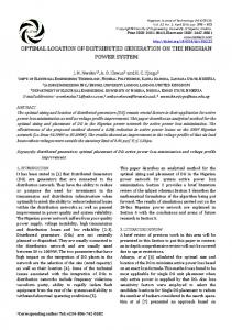
7.31%
TIT=9000 C TIT=10000C
7
TIT=11000C
6
19.18%
5
Compressor
Gasifier CHX GT & ORCT
4
20.69%
HXs Stack Utilized
Fig. 8. Component exergy loss and useful exergy of the plant at TIT=10000C and rp=6
3
2
1 4
6
8
10
12
14
16
Topping cycle pressure ratio
Fig. 7a. Variation in CHX unit (tube side) specific air consumption by volume with pressure ratio
GT high pressure end specific air consumption 3 by volume (m /kWeh)
44.55% 4.36% 2.3% 1.61%
20 18
TIT=9000 C TIT=10000C
16
TIT=11000C
14 12 10 8 6 4 2 2
4
6
8
10
12
14
Also some exergy losses occur in the other heat exchanging units and the turbines. Exergy destructions occurring in the other plant components are insignificant. The exergy destruction for the combustor-heat exchanger duplex unit is higher due to combustion and heat exchange across streams of high temperature. Some exergy loss also occurs at the other heat exchangers due to heat transfer across substantial temperature difference between flue gas and the working fluid. The exergetic efficiency values of the major exergy destroying components are plotted in Fig. 9 at different TITs. In each case optimum pressure ratio corresponding to maximum energetic efficiency is considered. It is seen that the exergetic efficiency for the turbines are about 90%, while that for the other units are much lesser. The TIT does not affect the gasifier performance. However the exergetic efficiency of the CHX unit is increasing at higher TITs because of the lower log mean temperature difference (LMTD) of the heat exchanger.
16
Topping cycle pressure ratio
100 0
Fig. 7b. Variation in GT high pressure end specific air consumption by volume with pressure ratio.
TIT=900 C 0 TIT=1000 C 0 TIT=1100 C
Exergy effcicency (%)
80
The CHX unit is one of the most important and critical components used in the plant. A high pressure high temperature heat exchanger is required for this purpose and the design needs to be optimized from the sizing and cost points of view.
60
40
20
It is seen from Fig. 3 that the plant is most efficient at about of rp=6. The performance of the plant along with sizing of the heat exchangers used in the plant is shown in Table 5, at different TITs. The size of the heat exchanger (block 6) used in the CHX unit is lower at TIT= 9000C due to higher high end temperature difference of the said unit. However, the efficiency value is lower compared to the efficiency value at TIT=11000C, although the size of the heat exchanger is almost same at the both TITs. Component exergy losses for the plant and the useful exergy of the plant with respect to the exergy input are shown in Fig. 8, for rp=6 and TIT=10000C. Fig. 8 shows that the major exergy destruction takes place in the gasifier and the CHX unit, together accounting for about 40% of the total input.
0
Gasifier
CHX
GT & ORCT
HXS
Fig. 9. Exergetic efficiency of the major exergy destructive components 5.
Conclusion
Thermodynamic modeling and performance analyses of a novel biomass based indirectly heated combined cycle plant are carried out in this paper. Also the effects of plant design operating parameters on the sizing of the major plant components have been reported. It is observed that the overall electrical efficiency of plant is maximized at some values of topping cycle pressure ratio, depending on the gas turbine inlet temperature. At a particular pressure ratio, the
779
INTERNATIONAL JOURNAL of RENEWABLE ENERGY RESEARCH S.Ghosh et al., Vol. 5, No. 3, 2015
Table 5. Performances of the plant and sizing of the heat exchangers at different operating conditions Performance of the Plant Required Biomass Flow rate (kg/s) Electrical Efficiency (%) Sizing of the Heat Exchangers Gas to Air Heater (block 6) ORC Superheater (block 8) Internal recuperator (block 13)
Scenario 1: rp=6, TIT=9000C
Scenario 2: rp=6, TIT=10000C
Scenario 3: rp=6, TIT=11000C
0.0065
0.0058
0.0055
45.019 ΔTH (K) 73.5 67.0 35.7
ΔTL (K) 164 3.94 9.43
Qtran
UA
118 54.2 13.5
1.04 2.44 0.68
overall electrical efficiency of the plant increases with TIT. The ESBC decreases with increase in TITs and the value gets minimized at a particular value of topping cycle pressure ratio at respective TITs. In addition, it is found that the gas turbine pressure ratio influence the sizes of the GT and CHX unit, high pressure ratio value resulting in reduced sizes of both. The size of the GT and CHX units is getting lowered at higher TITs for any given value of pressure ratio. From the Second Law analyses it is observed that maximum exergy destruction occurs in the gasifier, followed by the combustorheat exchanger duplex unit. It can be concluded form the study that the plant can be operated at the pressure ratio range of 6-8 and at higher GT TIT‟s. Although high TIT reduces the size of GT and CHX unit, it also requires expensive turbine materials and complex cooling arrangements leading to the increased capital cost of the plant. Acknowledgements The authors acknowledge the support provided by the Thermal Simulation and Computation (TSC) Lab at Mechanical Engineering Department of IIEST, Shibpur for carrying out the research work. The authors also acknowledge the cooperation of TU Delft (Delft University of Technology), The Netherlands, for providing the CycleTempo software to the TSC lab, which has been used for the present study. Nomenclature X: Mole of flue gas m: Mass flow rate cp: Specific heat at constant pressure w: Specific work T: Temperature h: Specific enthalpy s: Specific entropy exin: Exergy input exout: Exergy output exfuel: Fuel Exergy Greek Symbols rp =: Topping cycle pressure ratio : Multiplication factor Ƞgasi: Gasification efficiency ȠG: Generator efficiency ȠP: Pump Efficiency Ƞcc: Overall electrical efficiency Ƞexergetic: Exergetic efficiency
47.467 ΔTH (K) 54.9 65.4 35.7
ΔTL (K) 162 3.94 9.43
Qtran
UA
114.7 45.7 11.3
1.16 2.09 0.57
49.009 ΔTH (K) 51.2 85.8 35.7
ΔTL (K) 182.6 3.94 9.43
Qtran
UA
113 42.9 10.6
1.09 1.61 0.53
Abbreviation b: biomass C: Compressor CC: Combined cycle CHX: Combustor-heat exchanger duplex unit ESBC: Electrical specific biomass consumption fg: Flue gas GT: Gas turbines LHV: Lower heating value TIT: Turbine inlet temperature p.g: Producer gas ORC-T: Organic rankine cycle turbine OS: Organic vapor SUP: ORC-Superheater References [1] International Energy Outlook 2013. US Energy Information Administration. Department of Energy. (2013) Website: www.eia.gov/forecasts/ieo/pdf/0484(2013).pdf [2] B. Buragohain, P. Mahanta, and V.S. Moholkar, “Biomass gasification for decentralized power generation: The Indian perspective”, Renewable and Sustainable Energy Reviews, Vol. 14, pp. 73-92, 2010. [3] N.S. Barman, S. Ghosh, and S. De, “Gasification of biomass in a fixed bed downdraft gasifier-A realistic model including tar”, Bioresource Technology, Vol. 107, pp. 505511, 2012. [4] Ankur Scientific Energy Technologies Pvt. Ltd. Website: http://www.ankurscientific.com [5] A. Bhattacharya, D. Manna, B. Paul, and A Datta, “Biomass integrated gasification combined cycle power generation with supplementary biomass firing: Energy and exergy based performance analysis”, Energy, Vol. 36, pp. 2599-2610, 2011. [6] A. Datta, R. Ganguli, and L. Sarkar, “Energy and exergy analyses of an externally fired gas turbine (egft), cycle integrated with biomass gasifier for distributed power generation”, Energy, Vol. 35, pp. 341-350, 2010. [7] S. Soltani, S.M.S. Mahamoudi, M. Yari, and M.A. Rosen, “Thermodynamic analyses of an externally fired gas turbine combined cycle integrated with biomass gasification plant”, Energy Conversion and Management, Vol. 70, pp. 107-115, 2013.
780
INTERNATIONAL JOURNAL of RENEWABLE ENERGY RESEARCH S.Ghosh et al., Vol. 5, No. 3, 2015 [8] M.R. Yap, “Biomass integrated gasification combined cycles (BIGCC)”, University of New Orleans Theses and Dissertations, Paper 206, 2004. [9] P. Mondal, and S. Ghosh, “Biomass based indirectly heated combined cycle plant: Energetic and exergetic performance analyses”, International Journal of Innovative Research in Science, Engineering and Technology, Vol. 3, Issue 2, pp. 9285-9294, 2014. [10] P. Mondal, and S. Ghosh, “Thermal performance of an indirectly heated biogasification based combined cycle plant employing reciprocating compressor”, International Journal of Emerging Technology and Advanced Engineering. Vol.3, Special Issue 3, pp 186-192, 2013. [11] K.A. Al-attab, and Z.A. Zainal, “Performance of hightemperature heat exchangers in biomass fuel powered externally fired gas turbine systems”, Renewable Energy, Vol. 35, pp. 913–920, 2010. (Article) doi:10.1016/j.renene.2009.11.038 [12] I. Vankeirsbilck, B. Vanslambrouck, S. Gusev and M. D. Paepe, “Efficiency comparison between the steam cycle and the organic Rankine cycle for the small scale power generation”, 2nd European Conference on Polygeneration. 2011.
[13] S. Karellas and A. Schuster, “Supercritical Fluid Parameters in Organic Rankine Cycle Applications”, International Jurnal of Thermodynamics, Vol. 11, pp. 101108. 2008. [14] R. Chacartegui, D. Sánchez, J.M. Muñoz and T.Sánchez, “Alternative ORC bottoming cycles FOR combined cycle power plants”, Applied Energy, Vol. 86, pp. 2162-2170, 2009. [15] Cycle-Tempo Software, Release 5 (TU Delft). (2012) (Available: http://www.cycle-tempo.nl/.) [16] D. Vera, F. Jurado and J. Carpio, “Study of a downdraft gasifier and externally fired gas turbine for olive industry wastes”, Fuel Processing Technology, Vol. 92, pp. 19701979, 2011. [17] J. H. Horlock, Cogeneration-Combined Heat and Power (CHP), Pergamon Press, New York, 1987. [18] S. Ghosh and S. De, “First and second law performance variations of coal gasification fuel-cell based combined cogeneration plant with varying load” Proceedings of the Institution of Mechanical Engineers, Part A, Journal of Power and Energy, pp. 477-485, 2004.
781