http://eprints.qut.edu.au/ ... load sharing between parallel converters connected to microgrid ... HE interconnection of distributed generators (DGs) to the.
QUT Digital Repository: http://eprints.qut.edu.au/
Majumder, Ritwik and Ghosh, Arindam and Ledwich, Gerard F. and Zare, Firuz (2008) Power System Stability and Load Sharing in Distributed Generation . In Proceedings POWERCON2008 & 2008 IEEE Power India Conference, New Delhi, India.
© Copyright 2008 IEEE Personal use of this material is permitted. However, permission to reprint/republish this material for advertising or promotional purposes or for creating new collective works for resale or redistribution to servers or lists, or to reuse any copyrighted component of this work in other works must be obtained from the IEEE.
Power System Stability and Load Sharing in Distributed Generation Ritwik Majumder, Student Member, IEEE, Arindam Ghosh, Fellow, IEEE, Gerard Ledwich, Senior Member, IEEE, and Firuz Zare, Senior Member, IEEE
Abstract-- This paper describes control methods for proper load sharing between parallel converters connected to microgrid in a distributed generation system. The system stability is investigated during load sharing for safe operation and proper control. The dynamic response of the system is compared under different load conditions. Both inertia-less and inertial loads are considered in grid connected and islanded modes. A smooth transition between the grid connected and islanded mode is achieved. Its efficacy has been validated through simulation for various operating conditions. The impact of high values of real and reactive power droop controller gains on overall system stability is investigated. For a stable operation and quick attainment of steady state, an adaptive droop controller is proposed. The model of the microgrid power system is simulated in PSCAD. Index Terms-- Active and Reactive Power sharing, Distributed power supply, Islanding and Resynchronization, Microgrid, System Stability.
I. INTRODUCTION
T
HE interconnection of distributed generators (DGs) to the utility grid through power electronic converters has raised concern about proper load sharing between different DGs and the grid as well as the overall system stability. Microgrid can generally be viewed as a cluster of distributed generators connected to the main utility grid, usually through voltagesource-converter (VSC) based interfaces. Concerning the interfacing of a microgrid to the utility system, it is important to achieve a proper load sharing by the DGs. A load sharing with minimal communication is the best in the distribution level as the network is complex, can be reconfigured and span over a large area. The most common method is the use of droop characteristics. Parallel converters have been controlled to deliver desired real and reactive power to the system [1][4]. The system stability during load sharing has been explored by many researchers [2], [5]-[7]. Transient stability of power
The authors thank the Australian Research Council (ARC) for the financial support for this project through the ARC Discovery Grant DP 0774092 R. Majumder, A. Ghosh, G. Ledwich and F. Zare are with the School of Engineering Systems, Queensland University of Technology, Brisbane, Qld 4001, Australia.
978-1-4244-1762-9/08/$25.00 ©2008 IEEE
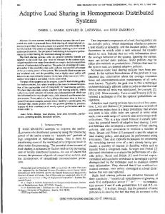
system with high penetration level of power electronics interfaced (converter connected) distributed generation is explored in [2]. Moreover, smooth transfer between the grid connected mode and the standalone or islanded mode is crucial in a microgrid operation. The system stability becomes very crucial during the transfer between grid connected and islanded mode. A seamless transfer can ensure a smooth operation with proper load sharing and attainment of quick steady state value. Adaptive Control of the droop controllers can ensure a much stable system [8]-[9]. A novel adaptive generator control based on step-ahead model predictive methodology is presented in [8], while [9] proposes an adaptive control strategy for interfacing distributed generations (DGs) from wind power to utility distribution grids. The aim of this paper is to set up power electronics interfaced microgrid containing distributed generators. Schemes for controlling parallel connected converters in islanded and grid connected mode are presented. The control techniques for a smooth transfer between these two modes are also discussed. A modular structure of the modified droop controller is presented. The structure can be modified to meet the control requirement for any other ac system. Also the effect of droop control parameters on system stability is investigated. A simple gain scheduling adaptive droop controller is proposed in this paper. II. SYSTEM STRUCTURE The basic power system model with two DG sources connected to the load at the point of common coupling (PCC) is shown in Fig. 1. In this, the system runs in islanded mode when the circuit breaker (CB) is open; otherwise it runs in grid connected mode. The load can be a constant impedance load or a motor load. In Fig. 1, the voltage source VS is the utility voltage that is connected to the PCC with a feeder of impedance RS + jXS. The current drawn from the utility is denoted by Ig, while Pg and Qg respectively are the real and reactive power supplied by the grid. It is assumed that the DGs are constant dc voltage sources Vdc1 and Vdc2. The converter output voltages are denoted by V1∠δ1 and V2∠δ2 and they are connected to the PCC through reactances jX1 and jX2 respectively. P1, P2 and Q1, Q2 represent the real and reactive power supplied by the DGs.
III. PROPOSED DROOP CONTROL METHOD The angle droop equation is used in the proposed control structure is given by (for converter-1)
δ1* = δ1rated − m1 × (P1rated − P1 ) V1* = V1rated − n1 × (Q1rated − Q1 )
(1)
Similarly, keeping the voltage magnitude difference between the DGs constant, the droop coefficient for reactive power is taken as n1Q1rated = n2Q2rated, where Q2rated is the reactive power rating of DG-2. In a similar fashion as (2-5), it can be shown that the reactive power sharing between the DGs is n1 × Q1 = n2 × Q2 ⇒
where V1rated and δ1rated are the rated voltage magnitude and angle respectively of DG-1, when it is supplying the load to its rated power levels of P1rated and Q1rated. The rated angles are determined from the maximum and minimum value of power supplied by the DGs and their load sharing ratio. The coeffici-
Q1 n2 Q1rated = = Q2 n1 Q2 rated
(6)
Thus the following power sharing relations between the two DGs are obtained m1 × P1rated = m2 × P2 rated (7) n1 × Q1rated = n2 × Q2 rated A. Modular Control Structure
Fig. 1. The system under consideration.
ents m1 and n1 respectively indicate the voltage angle drop visà-vis the real power output and the voltage magnitude drop vis-à-vis the reactive power output. These values are chosen to meet the voltage regulation requirement in the microgrid. It is assumed that all the DGs are all converter based and so the output voltage angle can be changed instantaneously. The angle droop will be able to share the load without any drop in system frequency. From the droop equations given in (1), we can write the angle equation for the DGs as,
δ1 = δ1rated − m1 × (P1rated − P1 ) δ 2 = δ 2 rated − m2 × (P2 rated − P2 )
Fig. 2. The modular control structure.
(2) IV. CONVERTER STRUCTURE AND CONTROL
where P2rated is the real power rating of DG-2. The angle difference then can be written as
δ1 − δ 2 = (δ1rated − δ 2 rated ) − m1 × (P1rated − P1 )
+ m2 × (P2 rated − P2 )
(3)
As the power supply from the DGs to the microgrid is controlled by the source angle, Pi ∝ δi, i = 1,2. The real power exchange between the DGs is kept constant by maintaining the angle difference constant. Then assuming (δ1 − δ2) = (δ1rated − δ2rated), from (3) we get, m1 × (P1rated − P1 ) = m2 × (P2 rated − P2 )
(4)
Now if we choose the droop coefficient such that m1P1rated = m2P2rated, from (4), we get the real power sharing between the DGs as, m1 × P1 = m2 × P2 ⇒
The modified droop controller, given by (1), is implemented in a modular structure as shown in Fig. 2. A similar structure is also used for DG2. In this structure, V1∠δ1 and I1 are used for calculating the real power (P1) and reactive power (Q1) injected by DG1. These are then used in (1) to calculate δ1 and V1. The reference magnitude V1* and its angle δ1* are then used to generate the instantaneous reference voltages of the three phases. These are then compared with the measures instantaneous phase voltages of V1. The resultant error is used in the feedback control to generate the firing pulses (u) of VSC-1. The feedback control and converter structure are discussed in Section IV.
P1 m2 P1rated = = P2 m1 P2 rated
(5)
The converter structure is shown in Fig. 3. This contains three H-bridge converters that are connected to the DG sources, denoted by Vdc1. The outputs of the H-bridges are connected to three single-phase transformers that are connected in wye for required isolation and voltage boosting [10]. The resistance Rf represents the switching and transformer losses, while the inductance Lf represents the leakage reactance of the transformers. The filter capacitor Cf is connected to the output of the transformers to bypass switching harmonics. The inductance L1 is added to provide the output impedance of the DG source. A. Converter Control
The equivalent circuit of one phase of the converter is shown in Fig. 5. In this, u⋅Vdc1 represents the converter output voltage, where u = ± 1. The main aim of the converter control is to generate u. From the circuit of Fig. 1, state space description of the system can be given as
I1∗p = I1∗q =
[P cos δ
+ Q1 sin δ1∗
[P sin δ
− Q1 cos δ1∗
1 V1∗ 1 V1∗
∗ 1
1
1
∗ 1
]
]
(14)
Therefore the phasor reference is given by ⎛ I1∗q ⎞ I1∗ = I1∗p + I1∗q tan −1 ⎜ ∗ ⎟ ⎜ I1 p ⎟ ⎠ ⎝
(15)
Once the references for the state vector (11) are obtained, the control law is computed from
(
uc = − K x − x ∗
Fig. 3. Converter structure.
)
(16)
where K is the gain matrix and x* is the reference vector. The gain matrix, in this paper, is obtained through linear quadratic regulator (LQR) design. From uc, the switching function is generated as in (10). V. SIMULATION STUDIES
Fig. 4. Equivalent circuit of one phase of the converter.
x� = Ax + B1uc + B2 vPCC
(8)
where uc is the continuous time version of switching function u. The discrete-time equivalent of (8) is x(k + 1) = Fx(k ) + G1uc (k ) + G2 vPCC (k )
(9)
Based on this model and a suitable feedback control law, uc(k) is computed. The switching function u is then generated as If uc > h then u = +1
(10)
elseif uc < −h then u = −1
where h is a small number. A state feedback controller is used and the controller is discussed below. B. State Feedback Controller Let the state vector be defined by
[
xT = vcf
icf
i1
]
(11)
Simulation studies are carried out with different type loads and operating conditions to check the system response and controller action. The system response with high value of real and reactive power droop gain and high output impedance is also investigated. Some of the results are discussed below. The system data used are given in Table I. A. System Response in Islanded Mode From Table I, it can be seen that DG1 is required to supply 1.25 times the power supplied by DG2. In the absence of the grid, the total power demand of the load is supplied by the DGs in the islanded mode. With any load change, the active and reactive power requirements change and the VSC reference voltage magnitude and angle must change to meet the new load requirement. Two types of load are considered here – constant impedance type load and motor load. Fig. 5 shows the system response with impedance load, where the values of the load impedances are doubled at 1 s. The load is changed back to its nominal value at 1.5 s. It can be seen that DG-1 shares more load than DG-2 in accordance with their droop characteristics, while the grid does not supply any power.
The reference for vcf is v1* mentioned in the previous subsection. Given V1* and δ1*, the phasor current through the capacitor Cf is given by
(
I cf∗ = ω C f V1∗∠ δ1∗ + 90°
)
(12)
The reference icf* is obtained from the instantaneous value of Icf*. We shall obtain the reference for i1 through its phasor quantity I1*. Note from Fig. 1 that if the references are strictly followed
P1 − jQ1 = V1*∠ − δ1* × I1* *
Let us define I1 =
I1p*
+j
I1q*.
(13) We then get from (10)
Fig. 5. System response with impedance load in islanded mode.
TABLE I
SYSTEM PARAMETERS System Quantities Systems Frequency (ωs) Source voltage (Vs) Feeder impedance (Rs + jXs) DG-1 DC voltage (Vdc1) Transformer rating VSC losses Source inductance (L1) Filter Capacitance (Cf) Angle droop coefficient (m1) Voltage droop coefficient (n1) DG-2 DC voltage (Vdc1) Transformer rating VSC losses Source inductance (L1) Filter Capacitance (Cf) Angle droop coefficient (m2) Voltage droop coefficient (n2) Passive load
Motor load (synchronous) Rated rms voltage (L-N) Rated rms line current Inertia constant Iron loss resistance Motor load (induction) Rated rms voltage (L-N) Rated rms line current Rated power
Values 100π rad/s 11 kV rms (L-L) 3.025 + j12.095 3.5 kV 3 kV/11 kV, 0.5 MVA, 2.5% reactance (Lf) 1.5 Ω 0.0578 H 185 μF 0.00026 rad/kW 0.02727 V/kVAr 3.5 kV 3 kV/11 kV, 0.5 MVA, 2.5% reactance (Lf) 1.5 Ω 0.0578 H 185 μF 0.000208 rad/kW 0.021816 V/kVAr The load is varied between 4.84 + j30.25 Ω and 102.85 + j157.3 Ω 6 kV 5 kA 1s 300 pu
controller is added to the voltage controller to ensure better load sharing and quick response. A state feedback control, which combines both voltage and current control modes, is used for this purpose. The state vector used for feedback contains the DG output voltage, output current and the current through the filter capacitor. The reference voltage magnitude and angle are calculated from the droop similar to the islanded mode. As power sharing by the DGs is rating based, the active and reactive power requirements from individual DG are calculated based on their rating. The output current reference is calculated from the power and voltage reference. The reference for the filter capacitor current is calculated from the voltage reference. Fig. 7 (a) shows the system response during a load change in the grid connected mode with impedance load, while Fig. 7 (b) shows system response with motor load. In Fig. 7 (a), the impedance of the load is suddenly increased at 1.5 s. It is brought back to nominal value at 2 s. It can be seen that the power outputs from the DGs remain constant all through the load changes barring the transients. As a consequence, the grid absorbs power when the load is reduced between 1.5 and 2 s. Similarly, in Fig. 7 (b), the load of the induction motor is increased at 2 s and it is brought back to nominal at 2.8 s. The extra power requirement is supplied by the grid, while the DGs continue to supply their rated power.
6 kV 0.11 kA 50 hp
Fig. 6 shows the results when the inductor motor is connected in parallel with the passive load at 2 s and disconnected at 2.75 s. The motor is operated in speed control mode. The change in active power is supplied by the DGs and proper load sharing with a quick steady state attainment is shown in Fig.6. The zero power from the grid confirms the islanded condition. Fig. 7. System response with (a) impedance load and (b) motor load in grid connected mode.
Fig. 6. System response with motor load in islanded mode.
B. System Response in Grid Connected Mode In the grid connected mode, it is assumed that the distributed generators supply their rated power. When the load requirement is less than the total rated power of the DGs, the excess power flows from DGs go to the grid. To avoid power swing the VSCs must supply the change in the power demand as quick as possible. To accomplish this, only a voltage control may not be sufficient. It is desirable that a current
C. Seamless Transfer between Grid Connected and Islanded Modes It is shown in the previous sections that a better load sharing and a rapid steady state attainment are achieved with the state feedback controller. A seamless transfer between islanded and grid connected mode is proposed here that uses an online load flow study. Let us assume that microgrid is operating in the islanded mode and it has to be resynchronized to the grid for grid-connected mode of operation. During resynchronization, the reference voltages of the DGs are changed to achieve same voltage magnitude and angle at PCC as the grid voltage while maintaining to supply the total power demand of the microgrid in desired ratio. Once the breaker CB (Fig. 1) is closed, the DGs start supplying their rated power and the rest of the power requirement is supplied by the grid. Figs. 8 show the response of the system during islanding and resynchronization with the impedance load when the islanding occurs at 1.5 s and the two systems are resynchronized at 2 s. Fig. 8 (b) and Fig. 8 (c) show the
currents of phase a of the two DGs and the grid during islanding and resynchronization operations, respectively.
where P1th and Q1th are the threshold values of the real and reactive powers respectively, m10 and n10 are the nominal droop coefficients given in Table I and m11 and n11 are the modified droop coefficients. The real and reactive power thresholds are load dependent. Fig. 10 shows the system response with and without adaptive controller where the total load changes from 0.35 MW to 0.67 MW at 0.05 sec. In this figure, the power using the adaptive controller is denoted by Piadap, i = 1,2. As the adaptive controller chooses lower droop gain after 0.05 s, the load sharing is not as accurate as linear droop controller. But system with the adaptive controller damps out oscillation much faster.
Fig. 8. System response during islanding and resynchronization with impedance load.
D. System Stability and Adaptive Droop Controller In the islanded mode of operation, the reference for the voltage magnitude and angle of the DGs are calculated by the droop controllers. The gains of the droop controller decide the drop in voltage magnitude and angle based on reactive and real power output of the VSC. To investigate the impact of the droop controller gains on the system stability, detail eigenvalue analysis of the system is performed. The modeling and the detail analysis is not presented in this paper. Fig. 9 shows the system response with high value of droop controller m and n. It is clear that a high value of controller gain can lead the system to instability. As a high gain can also promise accurate load sharing it is always better to have the gains of the droop controller as high as possible when the DGs are supplying much lower power than rated. When the real and reactive power output demands are high, lower droop gains are suitable for quick attainment of steady state.
Fig. 10. System response with adaptive droop controller.
Fig. 11 shows the similar comparison of adaptive and linear droop with the synchronous motor load where the DGs share the load equally. It can be seen that the system response with linear droop is oscillating in nature while with the adaptive droop controller system shows a much stable operation. Fig. 12 shows the system response with induction motor where the induction motor of 1 MW is connected to the microgrid at 0.05s. With the same value of droop controller gain, the linear droop control shows system oscillation while quick steady state is achieved by the adaptive controller.
Fig. 9. System response with high real and reactive droop gain.
To achieve this, gain schedule adaptive controller is proposed in this paper. In this the droop gains are selected based on the real and reactive power outputs of the DGs. The droop adjustment for DG1 follows the logic given below
For P1 < P1th , m1 = m10 For P1 ≥ P1th , m1 = m11
(17)
m11 = 0.75 × m10 For Q1 < Q1th , n1 = n10 For Q1 ≥ Q1th , n1 = n11 n11
=
0.75 × n10
(18)
Fig. 11. System response with Synchronous Motor Load.
[7]
M. C. Chandorkar, D. M. Divan, and R. Adapa, "Control of parallel connected inverters in standalone AC supply systems," IEEE Transactions on Industry Applications, Vol. 29, No. 1, pp. 136-143, 1993. [8] W. Lin and R.Cheuwng, “Model Adaptive Stability Control of DGLarge Engineering Systems Connected Distribution Systems”, Conference on Power Engineering, 10-12 Oct. 2007 , pp:67 - 72 [9] A. Hamlyn,; H. Cheung, W. Lin; Y. Cungang and R.Cheung “Adaptive Interfacing Control Strategy for Electricity Generations from Wind Power to Distribution Grids”, Large Engineering Systems Conference on Power Engineering, 10-12 Oct. 2007 , pp:78-83 [10] A. Ghosh and A. Joshi, “A new approach to load balancing and power factor correction in power distribution system,” IEEE Transactions on Power Delivery, Vol. 15, No. 1, pp. 417-422, 2000.
Fig. 12. System response with Induction Motor Load.
The droop controller gains are selected based on acceptable voltage regulation at each real and reactive power output levels. As the gain selection is based on the converter power output, is possible to control the converters based on local measurements. VI. CONCLUSIONS In this paper, a modular controller structure with modified angle droop control is proposed for better load sharing between the parallel connected converters in a distributed generation system. The angle droop can share the load without affecting the steady state frequency regulation. The efficacy of the controller is verified with impedance as well with motor loads. This paper shows the impact of droop controller gains on overall system stability and an adaptive droop controller is proposed. The performance of the proposed adaptive droop controller is verified for different load conditions. REFERENCES [1] [2]
[3]
[4] [5]
[6]
F. Katiraei and M. R. Iravani, “Power Management Strategies for a Microgrid with Multiple Distributed Generation Units,” IEEE Transactions on Power Systems, Vol. 21, No. 4, pp. 1821-1831, 2006. M. Reza, D. Sudarmadi, F. A. Viawan, W. L. Kling, and L. Van Der Sluis, “Dynamic Stability of Power Systems with Power Electronic Interfaced DG,” Power Systems Conference and Exposition, PSCE'06, pp. 1423-1428, 2006. M. Dai, M. N. Marwali, J. W. Jung, and A. Keyhani, “Power flow control of a single distributed generation unit with nonlinear local load,” Power Systems Conference and Exposition, PSCE’04. pp. 398-403, 2004. R. H. Lasseter, “MicroGrids,” Power Engineering Society Winter Meeting, Vol. 1, pp. 305-308, 2002. J. M. Guerrero, L. G. de Vicuna, J. Matas, M. Castilla, and J. Miret, “A wireless controller to enhance dynamic performance of parallel inverters in distributed generation systems,” IEEE Transactions on Power Electronics, Vol. 19, pp. 1205-1213, 2004. R. H. Lasseter and P. Paigi, "Microgrid: a conceptual solution," in Power Electronics Specialists Conference, PESC’04. Vol. 6, pp. 42854290, 2004.
Ritwik Majumder (S’07) received his B.E. in Electrical Engineering from Bengal Engineering College (Deemed University) in 2001 and his M.Sc. (Engg.) degree from Indian Institute of Science in 2004. From July 2004 to November 2004, he was with Tata Motor Engineering Research Centre in Jamshedpur, India. From November, 2004 to January 2006, he was with Siemens Automotive India and from January 2006 to May 2007, he was with ABB Corporate Research Centre, Bangalore, India. Since June 2007, he is a Ph.D. scholar in Queensland University of Technology. His interests are in Power Systems dynamics, Distributed Generation and Power Electronics Applications. Arindam Ghosh (S’80, M’83, SM’93, F’06) is the Professor of Power Engineering at Queensland University of Technology, Brisbane, Australia. He has obtained a Ph.D. in EE from University of Calgary, Canada in 1983. Prior to joining the QUT in 2006, he was with the Dept. of Electrical Engineering at IIT –Kanpur, India, for 21 ye ars. He is a fellow of Indian National Academy of Engineering (INAE) and IEEE. His interests are in Control of Power Systems and Power Electronic devices. Gerard Ledwich (M’73, SM’92) received the Ph.D. in electrical engineering from the University of Newcastle, Australia, in 1976. He has been Chair Professor in Power Engineering at Queensland University of Technology, Australia since 2006. Previously he was the Chair in Electrical Asset Management from 1998 to 2005 at the same university. He was Head of Electrical Engineering at the University of Newcastle from 1997 to 1998. Previously he was associated with the University of Queensland from 1976 to 1994. His interests are in the areas of power systems, power electronics, and controls. He is a Fellow of I.E.Aust. Dr Firuz Zare (M’97, SM’06) was born in Iran in 1967. He holds a PhD degree in Electrical Engineering from Queensland University of Technology in Australia. He has worked as a development engineer and a consultant in industry for several years. He has joined the school of engineering systems in QUT in 2006. His research interests are power electronic applications, pulse-width modulation techniques, renewable energy systems and electromagnetic interferences.