Sep 9, 2009 - medium at the flatâtop beam end, it is possible to extract high energy in a ... is the ability to select the field properties at either end of the cavity.
To be published in Optics Letters: Title: Gaussian mode selection with intra–cavity diffractive optics Authors: Andrew Forbes and Igor Litvin Accepted: 3 September 2009 Posted: 9 September 2009 Doc. ID: 113692
Published by
OSA
Gaussian mode selection with intra–cavity diffractive optics Igor A. Litvin1,2 and Andrew Forbes1,3 1
CSIR National Laser Centre, PO Box 395, Pretoria 0001, South Africa
2
Laser Research Institute, University of Stellenbosch, Stellenbosch 7602, South Africa
3
School of Physics, University of KwaZulu–Natal, Private Bag X54001, Durban 4000, South Africa
Published by
Abstract: We outline a resonator design that allows for the selection of a Gaussian mode by diffractive optical elements. This is made possible by the metamorphosis of a Gaussian beam into a
OSA flat–top beam during propagation from one end of the resonator to the other. By placing the gain
medium at the flat–top beam end, it is possible to extract high energy in a low–loss cavity. A
further feature of this resonator is the ability to select the field properties at either end of the cavity
almost independently, thus opening the way to minimize the output divergence while simultaneously maximizing the output energy.
OCIS codes: (140.3410) Laser resonators; (140.3300) Laser beam shaping.
Traditionally laser beams are generated in Fabry–Perot type resonators, where the mirror surfaces
are spherical. When the resonator is chosen to be stable, a low–loss fundamental mode may be
forced to oscillate by suitable choice of internal aperture. However, the power loss discrimination between the low order modes is often poor, and the small beam waist results in poor power extraction. Conversely, if an unstable configuration is employed, the mode volume is large and mode discrimination good, but this is at the expense of high intrinsic loss for the oscillating modes, making such cavities suitable only for lasers with high gain. A major advance to overcome such problems was the introduction of so–called graded–phase mirrors [1,2]. It was shown that a
1
resonator with grade–phase mirrors could discriminate against undesired modes by altering the generalized radius of curvature of the incoming beam according to [1]:
∞
1 1 = − R2 R1
dφ M 2 ψ 1 ( x)dx dx
∫ x
−∞
∞
∫x
,
(1)
ψ 12 ( x)dx
2
−∞
Published by
where R1 and R2 are the generalized radii of curvature just prior and just after the graded–phase mirror (φM) respectively. Equation (1) indicates that the real radius of curvature of the beam is
OSA changed by the phase function of the graded–phase mirror, and moreover, this change is dependent
on the incoming amplitude of the field, ψ1(x). In other words, it is possible for such a graded–phase
mirror to discriminate against modes that do not have the proper distribution, ψ1(x). However, when the graded–phase mirror is spherical (assuming the paraxial limit), the change in curvature of
the beam becomes independent of the incoming amplitude of the field, ψ1(x), since the derivative in
the integrand becomes proportional to x. Unfortunately, for Gaussian beams the required graded–
phase mirror surface is spherical, therefore annulling the aforementioned discrimination process. To put this another way, the graded–phase mirror approach cannot be used to select between any of
the Hermite–Gaussian (in resonators with rectangular symmetry) or Laguerre–Gaussian (in resonators with circular symmetry) modes, and therefore by definition not the lowest order Gaussian mode either. The reason is simply that under free space propagation all such fields have
an identical real radius of curvature, defined by spherical wavefronts, and thus reverse propagating such beams to find the appropriate conjugate always returns a solution that requires a spherical curvature mirror. Note that the form of the graded–phase mirror here might in fact be a deformable mirror, a diffractive mirror, or approximated by a transmission diffractive optical element or even
2
an intra–cavity phase–only spatial light modulator. The limitation is not in how the phase element is implemented, but rather by the fundamental physics governing the propagation of Gaussian beams. It is however possible to overcome this problem by metamorphosing a Gaussian beam into another desired shape. Since the resulting propagation will not follow that of a Gaussian beam in free space, the resulting beam after propagation may be discriminated against in the usual manner. In this Letter we propose a resonator concept that produces a Gaussian mode using diffractive
Published by
optical elements by intra–cavity metamorphosis of a Gaussian beam at the output coupler end, to a flat–top beam at the opposite end of the cavity. It is well known that flat–top beams have been
OSA favored over Gaussian beams in those applications where high power extract is required [3]. This is
because flat–top beams enjoy a larger mode volume for the same Gaussian beam size, and they overcome the poor saturation and energy extraction at the edge of Gaussian beams.
Such a
resonator has the possibility of low diffraction loss, and high energy extraction, while producing a low divergence Gaussian beam.
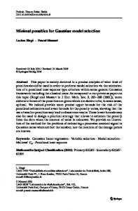
We illustrate the concept graphically in Figure 1: a flat–flat resonator is modified with suitable
intra–cavity diffractive optical elements, where the sum of the flat mirror and adjacent transmission
DOE mimics a graded–phase mirror. Our task is to outline the functional form of the two DOEs.
To do this, we consider a circular Gaussian field at mirror M1 of the form u1(ρ) = exp[–(ρ/w0)2],
where w0 is the radius where the field is at 1/e of its peak value. If the DOE at mirror M1 is made up of a Fourier transforming lens and a phase only transmission element, φSF, and the resonator length is selected to match the focal length of the Fourier transforming lens (L = f), then the resulting field at mirror M2 will be given by:
3
u2 (r ) = −i
ikr 2 ∞ k u1 ( ρ ) exp[iφ SF ( ρ )]J 0 krρ ρdρ . exp(ikf ) exp f f 2 f 0
∫
(2)
We may apply the method of stationary phase to find an analytical solution for the phase function φSF, such that the field u2 is a perfect flat–top beam, of width wFTB [4]: ρ
φSF ( ρ ) = β
π 2
w0
∫
1 − exp(−ξ 2 ) dξ ,
0
(3)
Published by
OSA where a dimensionless parameter β has been introduced, defined as
β=
2πw0 wFTB . fλ
(4)
Since the flat–top beam is generated only at the Fourier plane of the lens, the effective phase profile of the DOE at mirror M1 mimicking both the lens and this element is given by:
φ DOE1 ( ρ ) = φ SF ( ρ ) −
kρ 2 , 2f
(5)
where the second term is the required Fourier transforming lens. In addition to an exact function for the first DOE’s phase, we state here (the proof is beyond the scope of this Letter and will be published elsewhere) that it is also possible to use the stationary phase method to extract a closed form solution for the phase of the DOE at mirror M2 as:
4
k 2 β rρ (r ) , r + φ SF ( ρ (r )) − wFTB w0 2 f
φ DOE 2 (r ) = argexp i
(6a)
where from the stationary phase condition r wFTB = ∂φSF ∂ρ we may find the unknown function:
π wFTB
ρ (r ) = w0 − ln 1 −
2r
2
,
Published by
(6b)
OSA Such a mirror will reproduce our Gaussian field with a flat wavefront at mirror M1, as desired.
Moreover, since the field at mirror M2 is a flat–top beam, there exists the possibility for uniform
gain saturation and high energy extraction if the gain medium is placed at this end of the resonator cavity.
It is instructive to consider the flat–top beam as a Flattened Gaussian Beam (FGB) of order
N [5]. The advantage of this profile over others is that it offers a simple analytical expression for
the beam profile at any propagation distance z, and furthermore, the Gaussian and flat–top profiles
are returned when N = 1 and N →∞ respectively. It is well known that flat–top beams are able to
fill a larger mode volume without the adverse affects of diffraction for similar sized Gaussian beams, due to the fast drop in intensity at the edges of the beam. In fact, it has been pointed out [6] that even a relatively low order FGB fills nearly four times more volume of a laser rod of diameter d = 3w0 than a Gaussian beam could, due to the smaller Gaussian field required in order to avoid hard edge clipping. In addition, the peak intensity of the FGB is smaller than that of a Gaussian beam of the same width and energy, reaching a minimum of only half the peak intensity when the order N >> 1. This is important when considering practical issues such as thermally induced stress
5
fracture, and thermal aberrations, in solid state gain materials. However, the disadvantage of such beams is the larger beam quality factor, and hence shorter Rayleigh range, thus reducing the useful length of the gain medium that will experience the uniform beam. The Rayleigh range of such a beam is given by zR/N where zR is the Rayleigh range of a Gaussian beam with the same parameters [5]. Clearly the price to be paid for a perfect flat–top beam (N > 100) is a significantly reduced Rayleigh range. These results are important in understanding the depth of field of the flat–top beam for gain extraction purposes.
Published by
In our design these points may be balanced through the use of Eq. (4); herein lies the salient parameters of the desired Gaussian beam size, the desired flat–top beam size, and the degree of
OSA flatness of the beam itself, β, which is proportional to the order of the FGB. If all three are to be
chosen independently for a particular wavelength, then the focal length of the Fourier transforming lens, and hence the length of the resonator, must be appropriately selected using Eq. (4), while the phase functions of the DOEs maintain the same functional form, i.e., only the dimensionless
parameter β changes in the equations. The ease with which the DOEs may be calculated for various
parameters of the desired mode is a unique feature of this resonator design. Essentially the propagation of the Gaussian beam outside the resonator may be determined almost independently of the flat–top mode inside the gain volume. There are obvious advantages to such a flexible design.
To expound on the concept, we consider the example of a resonator designed to produce a
Gaussian beam with a width of w0 = 1 mm, from which we deduced the required Gaussian beam half angle divergence of θ = λ/πw0 = 0.34 mrad (λ = 1064 nm).
With this fixed, we may now
select any two of the remaining three parameters: resonator length, flat–top beam size, or degree of flatness of our flat–top beam (β). If our gain medium is a rod of radius 3 mm and length 100 mm, then we may wish to select a flat–top beam of wFTB = 2 mm, while β = 23 will ensure a high fidelity flat–top beam that propagates throughout the gain length without significant changes. From Eq. (4)
6
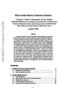
we then deduce that the required resonator length (L = f) is given by ~500 mm. Figure 2 shows the results of a numerical simulation of the aforementioned resonator, starting with a field of random noise and propagated following the Fox–Li approach [7] until stability, with mirror radii of 4w0. Figure 2(a) shows the stable fields at either end of the resonator – the expected Gaussian and flat– top beams as per the design. Figure 2(b) shows the numerically determined phase of each DOE. Near the beam edge there is a slight discrepancy between the analytically calculated phase of the second DOE and the numerically determined phase; this is due to the use of the stationary phase
Published by
approximation in the analytical equations.
The same design procedure may be adopted to
accommodate other constraints, for example, the length of the resonator or the complexity of the
OSA DOEs themselves.
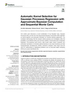
It is also instructive to extend the example above to consider the mode discrimination of this
resonator. Without any gain considerations, the fundamental Gaussian/flat-top mode has the lowest
loss (0.34%) with the next lowest loss modes shown in Figure 3. These three modes have higher losses, by factors of 1.06 (TEM10), 1.18 (TEM01) and 1.47 (TEM11) respectively, but also have
significantly smaller mode volumes within the gain region, decreased relative to the fundamental
mode by a factor of 0.65 (TEM10), 0.29 (TEM01) and 0.33 (TEM11) respectively. Thus when gain is
included (at the flat-top end), the significantly increased volume for our Gaussian/flat-top mode
should aid mode discrimination, whereas in conventional resonator designs it is often the reverse: the Gaussian mode would have a lower mode volume than other competing modes. In a practical
system the discrimination could be further enhanced by the inclusion of suitable apertures on the Gaussian end of the resonator. In conclusion, we have shown that it is possible to design a resonator for a Gaussian beam output but with the advantage of a flat–top beam in the gain region. The metamorphosis from one beam shape to another is achieved through phase–only optical elements. Such a configuration lends
7
itself to high energy extraction with good competing mode discrimination in a low divergence output mode. References 1. P.A. Belanger, C. Pare, “Optical resonators using graded-phase mirrors,” Opt. Lett. 16, 1057– 1059 (1991). 2. C. Pare, P.A. Belanger, “Custom Laser Resonators Using Graded-Phase Mirror,” IEEE J. of Quantum Electron. 28, 355–362 (1992).
Published by
3. J. R. Leger, D. Chen, Z. Wang, “Diffractive optical element for mode shaping of a Nd:YAG laser,” Opt. Lett. 19, 108–110 (1994).
OSA 4. L. A. Romero, F. M. Dickey, “Lossless laser beam shaping,” J. Opt. Soc. Am. A 13, 751–760 (1996).
5. F. Gori, “Flattened gaussian beams,” Opt. Commun. 107, 335–341 (1994).
6. A. E. Siegman, Lasers (University Science Books, 1986).
7. G. Fox and T. Li, “Resonant Modes in a Maser Interferometer,” Bell Syst. Tech. J. 40, 453–488 (1961).
8
Figure Captions: Figure 1: Schematic of the resonator concept.
Figure 2: Numerical results of the Fox–Li analysis, showing (a) Gaussian and flat–top beams after starting from random noise, and (b) calculated phase profile of each DOE, with the analytical phase
Published by
function for the second DOE shown as data points.
OSA Figure 3: Cross-sections of the first three higher-order competing modes at mirror M2.
9
Figures:
Published by
OSA Figure 1: Schematic of the resonator concept.
Figure 2: Numerical results of the Fox–Li analysis, showing (a) Gaussian and flat–top beams after starting
from random noise, and (b) calculated phase profile of each DOE, with the analytical phase function for the second DOE shown as data points.
Figure 3: Cross-sections of the first three higher-order competing modes, shown at mirror M2.
10
Published by
OSA 11