6th FP Project FP6 -503192
Generic Verification and Validation Masterplan J. Teutsch, D.M. Dehn, H.B. Nijhuis NLR
Document No: Version No. Classification: Number of pages:
D6.1.1 V1.0 Confidential 71
Confidential
Project Funded by European Commission, DG TREN The Sixth Framework Programme Strengthening the competitiveness Contract FP6 -503192
Project Manager Michael Roeder Deutsches Zentrum für Luft und Raumfahrt Lilienthalplatz 7, D-38108 Braunschweig, Germany Phone: +49 (0) 531 295 3026, Fax: +49 (0) 531 295 2180 e-mail:
[email protected] Web page: http://www.dlr.de/emma
© 2006, EC Sponsored Project EMMA (Copyright Notice in accordance with ISO 16016) The reproduction, distribution and utilisation of this document as well as the communication of its contents to other without explicit authorisation is prohibited. This document and the information contained herein is the property of Deutsches Zentrum für Luft- und Raumfahrt and the EMMA project partners. Offenders will be held liable for the payment of damages. All rights reserved in the event of the grant of a patent, utility model or design. The results and findings described in this document have been elaborated under a contract awarded by the European Commission, under contract FP6 -503192.
1.4 Aeronautics and Space Project FP6-503192 “EMMA1” Generic Verification and Validation Masterplan - EMMA
Distribution List Member Type
No.
Sub-Contractor Customer
Additional
POC
Distributed
Internet
http://www.dlr.de/emma/
2005-12-12
Intranet
http://www.dlr.de/emma/members/
2005-12-12
1
DLR
Joern Jakobi, Michael Roeder
2005-12-12
2
AENA
Jose Miguel de Pablo
2005-12-12
3
AIF
Patrick Lelièvre
2005-12-12
4
AMS
Giuliano D'Auria
2005-12-12
5
ANS-CR
Miroslav Tykal
2005-12-12
6
BAES
Stephen Broatch
2005-12-12
7
STAR
Max Koerte
2005-12-12
8
DNA
Nicolas Marcou
2005-12-12
9
ENAV
Antonio Nuzzo
2005-12-12
10
NLR
Jürgen Teutsch
2005-12-12
11
PAS
Alan Gilbert
2005-12-12
12
TATM
Stephane Paul
2005-12-12
13
THAV
Alain Tabard
2005-12-12
14
AHA
David Gleave
-
15
AUEB
Konstantinos G.Zografos
2005-12-12
16
CSL
Libor Kurzweil
2005-12-12
17
DAV
Niels-H.Stark
18
DFS
Klaus-Ruediger Täglich
2005-12-12
19
ERC
Nigel Makins
2005-12-12
20
ERA
Zdenek Svoboda
21
ETG
Thomas Wittig
2005-12-12
22
MD
Phil Mccarthy
-
23
SICTA
Claudio Vaccaro
2005-12-12
24
TUD
Christoph Vernaleken
2005-12-12
CSA
Karel Muendel
-
EC
Cesare Bernabei
-
EC
Morten Jensen
2005-12-12
EUROCONTROL
Paul Adamson
-
Web
Contractor
Name
Save Date: 2006-08-17 Confidential File Name: EMMA_SP6_TW_CO_NLR_002_D6-1-1_Generic_VV_Masterplan_V1-0.doc
-
-
2 Version V1.0
1.4 Aeronautics and Space Project FP6-503192 “EMMA1” Generic Verification and Validation Masterplan - EMMA
Document Control Sheet
Project Manager:
M. Roeder
Responsible Author:
J. Teutsch
NLR
D.M. Dehn
NLR
K. Zografos
AUEB
N. Makins
EEC
F. van Schaik
NLR
J. del Molino Blanco
AENA
H.B. Nijhuis
NLR
Additional Authors:
Subject / Title of Document:
Generic Verification and Validation Masterplan
Related Task('s):
WP6.1
Deliverable No.:
D611
Save Date of File:
2006-08-17
Document Version:
V1.0
Reference / File Name:
EMMA_SP6_TW_CO_NLR_002_D6-1-1_Generic_VV_Masterplan_V1-0.doc
Number of Pages:
71
Dissemination Level:
Confidential
Target Date:
2005-02-28
Change Control List (Change Log) Date
Issue
Changed Chapters
Comment
2004-09-24
0.01
All
Draft
2004-10-01
0.02
All
Draft for comments
2004-10-31
0.03
All
Comments from EEC, SICTA, NLR
2004-12-09
0.04
All
TRANSLOG contribution, typo and layout
2005-01-10
0.05
2.1.4
TRANSLOG contribution, typo and layout
2005-01-11
0.06
2.1.3
Eurocontrol contribution, typo
2005-02-28
0.07
1.1, 2.1.3, 2.1.4.2, 2.1.4.4, Eurocontrol contribution update, comments 2.1.5 from SP6 progress meeting #5
2005-04-25
0.08
1, 2.1.1, 2.1.3, 2.1.4, 2.1.8
Consortium review
2005-08-12
0.09
2.1.7.1
Review comments TU Darmstadt
2005-12-06
0.9a
1.2, 2.1.1, 2.1.3, 2.1.4, 2.1.7, Review comments European Commission 2.1.8, 2.1.9, 2.3
2005-12-12
1.0
N/A
EU approval
Save Date: 2006-08-17 Confidential File Name: EMMA_SP6_TW_CO_NLR_002_D6-1-1_Generic_VV_Masterplan_V1-0.doc
3 Version V1.0
1.4 Aeronautics and Space Project FP6-503192 “EMMA1” Generic Verification and Validation Masterplan - EMMA
Table of Contents 1 Introduction ....................................................................................................................................... 5 1.1 Document Context ...................................................................................................................... 5 1.2 Document Scope and Purpose ..................................................................................................... 8 2 Application of MAEVA to EMMA Project ...................................................................................... 11 2.1 Step 1: Identification of Aims, Objectives and Hypotheses ........................................................ 11 2.1.1 Step 1.1: ATM Problem and EMMA Operational Concept Definition ................................. 12 2.1.2 Step 1.2: Identification of Stakeholders............................................................................... 18 2.1.3 Step 1.3: Identification of Verification and Validation Aims ............................................... 24 2.1.4 Step 1.4: Identification of Validation and Verification Objectives ....................................... 29 2.1.5 Step 1.5: Establishing Platform Requirements..................................................................... 44 2.1.6 Step 1.6: Identification of Metrics and Indicators ................................................................ 44 2.1.7 Step 1.7: Identification of Hypotheses................................................................................. 45 2.1.8 Step 1.8: Definition of High-level Experimental Design...................................................... 48 2.1.9 Step 1.9: Definition of Statistical Significance .................................................................... 53 2.2 Step 2: Planning and Preparing the Validation Exercise ............................................................. 55 2.2.1 Step 2.1: Techniques, Facilities and Detailed Experimental Design ..................................... 55 2.2.2 Step 2.2: Preparation of Outline Plan .................................................................................. 56 2.2.3 Step 2.3: Scenario Specification.......................................................................................... 56 2.2.4 Step 2.4: Produce Site-specific V&V Management Plan...................................................... 57 2.2.5 Step 2.5: Preparation of the Exercise Runs .......................................................................... 58 2.3 Step 3: Conduct of Validation and Verification Exercises ......................................................... 59 2.4 Step 4: Analysis of Validation and Verification Data ................................................................. 60 2.4.1 Step 4.1: Carrying Out of Predefined Analysis .................................................................... 60 2.4.2 Step 4.2 Results and Interpretation of Data ......................................................................... 60 2.5 Step 5: Conclusions and Recommendations .............................................................................. 61 2.5.1 Step 5.1: Develop Conclusions and Recommendations........................................................ 61 2.5.2 Step 5.2: Write Report ........................................................................................................ 61 2.5.3 Step 5.3: Dissemination of Results...................................................................................... 61 3 References ....................................................................................................................................... 62 4 Abbreviations .................................................................................................................................. 65 5 List of Figures and Tables ................................................................................................................ 69 5.1 List of Figures ........................................................................................................................... 69 5.2 List of Tables ............................................................................................................................ 69 Appendix 1 Operational Problem List ............................................................................................. 70
Save Date: 2006-08-17 Confidential File Name: EMMA_SP6_TW_CO_NLR_002_D6-1-1_Generic_VV_Masterplan_V1-0.doc
4 Version V1.0
1.4 Aeronautics and Space Project FP6-503192 “EMMA1” Generic Verification and Validation Masterplan - EMMA
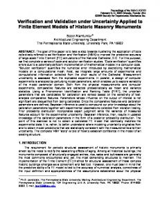
1 Introduction 1.1 Document Context In the near future, the demand for air transport in Europe is expected to increase considerably. Current airport capacity is expected to become one of the bottlenecks for further growth. This caused the European Union to support research on A-SMCGS in the subsequent framework programs until now. These projects resulted in new A-SMCGS concepts, new systems, and new procedures. A common finding of these studies (like ATHOS, DEFAMM, BETA) is that validation practices are often insufficiently standardised to cover the complexity of advanced technology implementation. At the same time, coherent and consistent validation is important for choosing the optimal concepts, systems and procedures. Validation in the EMMA1 framework refers to all activities during the development of A-SMCGS concepts, systems and procedures aiming at implementing the right concept, procedure or system. The concept development itself is carried out in EMMA SP1 and thus is not part of this document. Developing and implementing the right concepts, procedures and systems (in terms of safety, efficiency, usability etc.) is of the utmost importance at a time where advances in ATM are urgently required. Before successful validation takes place, verification, i.e. testing against system specifications should take place. This Sub-project (SP6) also covers the description of the verification phase. Only if verification results in an A-SMGCS performing at the required level, successful validation of the concept can be started. Therefore, the verification and validation effort (called V&V) also includes the definition of minimum required performance criteria for verification, to allow for successful validation. The carrying out of the verification and validation takes place in other sub-projects of EMMA. In summary: Verification is testing against predefined technical specifications, technical functional testing (‘did we build the system right?’). Validation is testing against operational requirements (as defined by stakeholders and written down in the OSED document of EMMA SP1), man-in-the-loop, ATM procedure testing, case studies (‘did we build the right system?’). In the so-called V-shape methodology, which is based on ESA and ANSI/IEEE standards [15] the interrelationship between the two terms has been described. ESA and ANSI/IEEE have established a verification approach that fits into an overall system life cycle (see Figure 1-1). Figure 1-1 shows all verification activities. As can be seen from the interrelationships between the different steps there is a number of iterations or cycles, that give feedback at any of the development stages and might even lead to a complete re-design of the systems. The feedback essentially is the verification of the output specification against its input specification. This seems to be surprising, as the definition of requirements usually is a validation activity, which would ban verification to take place in the lower part of the V-shape where system development enters the design and execution work phases. However, this only shows that there must be an overlap between validation and verification. In fact, validation is also considered as end-to-end verification, meaning that acceptance tests usually occur as validation activities.
Save Date: 2006-08-17 Confidential File Name: EMMA_SP6_TW_CO_NLR_002_D6-1-1_Generic_VV_Masterplan_V1-0.doc
5 Version V1.0
1.4 Aeronautics and Space Project FP6-503192 “EMMA1” Generic Verification and Validation Masterplan - EMMA
Figure 1-1: Life Cycle Verification Approach in System Development To ensure that for complex systems there will be no major redevelopment cycle after an acceptance test, it is necessary to carry out validation and verification at lower levels of detail or complexity first. For EMMA this means that the work made in earlier projects has to be considered (DEFAMM, BETA, etc.). Furthermore, the subdivision of EMMA in two phases allows for going through a first validation and verification life cycle with a lower level of detail.
ATM Problem
Concept
Validation
Requirement Integration Design Verification Debugging Source
Figure 1-2: Adapted V-shape concerning ATM Procedures and Systems Save Date: 2006-08-17 Confidential File Name: EMMA_SP6_TW_CO_NLR_002_D6-1-1_Generic_VV_Masterplan_V1-0.doc
6 Version V1.0
1.4 Aeronautics and Space Project FP6-503192 “EMMA1” Generic Verification and Validation Masterplan - EMMA
The basic V-shape approach for system development as depicted in Figure 1-1 can be extended and adapted to represent system and procedure development in ATM. This was done during the EMMA proposal phase (cf. Ref. [1], Section 18.1.3.2). In that representation the following steps were proposed: -
Identification of the user needs and definition of the ATM problem to be solved
-
Definition of a concept to help the user solve the problem
-
Specification of requirements of systems and procedures that are needed to support the concept
-
Design phase for procedures and systems
-
Development phase resulting in ‘source’ modules for systems and procedures
Again, as in the case of the ESA and ANSI/IEEE shape, the horizontal loops represent the verification activities, and ultimately the validation of the ATM procedures and systems. The following steps were identified: -
Debugging of subsystems and procedures
-
Integration of subsystems and procedures
-
Verification phase (testing the requirements)
-
Validation phase (including the user acceptance of the product)
It would be superfluous to go into the details of each of the phases described in the V-shape. It should suffice to say that for EMMA it is expected that verification activities occur for all software or technical systems and sub-systems according to the ESA [15] and ANSI/IEEE (standard 1012) or closely related and well-established guidelines. Thus, it will be possible to consider user input at the very beginning of the project. For example, controllers and pilots could be asked to check the concept or a prototype could help to identify requirements that were not adequately defined at the beginning. The two big advantages of working according to the V-shape are that errors can potentially be detected in the very early stages of a project and that user involvement is absolutely required. The V-shape model is not the only model for system development known from the literature. Another example is the Cyclic or Spiral model. The principle is the same for all: verification and validation are applied in early stages of the development process in order to render the process cost-efficient and goaloriented. In the Verification and Validation (V&V) sub-project of the EMMA project this working method will be applied. It must be noted in that regard that in EMMA a clear distinction will be made between technical verification activities and operational verification activities. Operational verification will be part of operational feasibility testing which includes the testing of operational requirements set by the system users and tuned during system parameter testing in an operational environment (real-time simulator, shadow-mode environment or real operational environment). This means that all operational testing activities will be part of validation. Generally, the following stages in verification and validation were identified: -
Technical tests are conducted in order to assess the technical performance of A-SMGCS equipment and therefore represent the verification subject.
Validation activities will be split into three major building blocks, namely: -
Operational feasibility addressing the definition of the operational use of the equipment in accordance with the system performance assessed during verification. This stage includes the ‘operational verification’ and ‘system parameter tuning’ activity as well as ‘system usability’ aspects. These activities are necessary before further validation of the system with respect to possible improvements and benefits can take place.
Save Date: 2006-08-17 Confidential File Name: EMMA_SP6_TW_CO_NLR_002_D6-1-1_Generic_VV_Masterplan_V1-0.doc
7 Version V1.0
1.4 Aeronautics and Space Project FP6-503192 “EMMA1” Generic Verification and Validation Masterplan - EMMA
-
Operational improvements (capacity, efficiency, safety, Human Factors) are investigated when both system requirements and user requirements are met by the system as verified and evaluated in the previous stages. In this stage the performance of the specific ATM concept (possibly related with new technology) can be assessed.
-
Operational benefits are looked at in this last stage. Only when it has been verified that the system is working properly according to all technical and operational requirements and when it has been validated that there will be operational improvements, it will be possible to translate such improvements into monetary terms.
Operational Benefits
Validation
Operational Improvements
Operational Feasibility
Verification
Technical Tests
Figure 1-3: Verification and Validation Activity Stages The four stages of verification and validation activities are illustrated in Figure 1-3. This view of verification and validation is coherent with the V-shape methodology as it allows for loops within each of the stages and in-between stages if it is deemed necessary. However, it should also be clear that only a high maturity of the concept to be validated and a high maturity of the validation environment will lead to meaningful results regarding operational improvements and benefits.
1.2 Document Scope and Purpose During the proposal phase of the EMMA Phase 1 project, it was decided to use the Master European Validation Plan (MAEVA) project’s Validation Guideline Handbook (VGH) as the basis for EMMA Verification and Validation (V&V). The MAEVA approach is fairly well accepted throughout the European ATM domain (see Ref. [12]). Nevertheless, several adaptations of MAEVA were proposed in Europe (among which one by EEC), but because these updates are not generally agreed and not easily accessible for all partners, it was decided to stick to the original MAEVA methodology. Admittedly, there are some discrepancies between the basic steps of the MAEVA guidelines and the verification and validation master plan of the EMMA project. Save Date: 2006-08-17 Confidential File Name: EMMA_SP6_TW_CO_NLR_002_D6-1-1_Generic_VV_Masterplan_V1-0.doc
8 Version V1.0
1.4 Aeronautics and Space Project FP6-503192 “EMMA1” Generic Verification and Validation Masterplan - EMMA
At a first glance, it seems that MAEVA uses another definition of the term ‘Verification’. MAEVA defines this term as the ‘process of evaluating the products of a given system development activity to determine correctness and consistency with respect to the products and standards provided as input to that activity’. In essence this means that verification is indeed testing against predefined technical specifications. Interpreting this definition a bit wider, however, could lead to the opinion that tuning of operational parameters of a system with the help of potential users of that system could be part of the process as well. Yet, in the EMMA project, verification will point to technical system tests only, in order to clearly separate operational testing from purely technical system requirement testing. The general problem with applying the MAEVA guidelines is that MAEVA does not specifically address the verification topic. Therefore, some additional attention needs to be devoted to this subject. In the present document entitled D6.1.1 - Generic Validation and Verification Masterplan, the MAEVA approach will be applied to the EMMA A-SMCGS case. MAEVA addresses validation following an approach within which verification is not specifically addressed, though it is embedded into the overall validation exercise. This circumstance makes it necessary for EMMA to supplement the MAEVA steps for system validation with those verification aspects that are considered in EMMA. The MAEVA approach consists of 5 steps (and a number of sub-steps) as outlined in Table 1-1. Step
1. Identification of Validation Aims, Objectives and Hypotheses
2. Validation Design: Planning and Preparing the Validation Exercise
3. Conduct of Validation Exercises
Sub-step
Activity
Outputs
1.1
Understanding the ATM problem and operational concept
Clearly defined scope, and operational concept
1.2
Identification of stakeholders
List of stakeholders
1.3
Identification of validation aims
List of aims
1.4
Identification of validation objectives
List of objectives
1.5
Establishing the validation platform requirements
List of requirements
1.6
Identification of metrics and indicators
List of suitable metrics and indicators
1.7
Identification of hypotheses
List of hypotheses
1.8
Definition of high-level experimental design
Experimental design
1.9
Pre-trial definition of operational and statistical significance
Predefined significance levels
2.1
Selection of techniques, facility and detailed experimental design
Experimental plan Configured V&V facilities Measurements definition
2.2
Preparation of outline plan Validation timeline
2.3
Scenario specification
Scripted scenarios
2.4
Production of the overall site specific V&V management plan
2.5
Preparation of the exercise runs
N/A
Conduct of validation exercises at different test sites.
Predefined validation data
4.1
Carrying out of predefined analysis
Mathematical results with significance indication
4.2
Interpretation of results
Results translated from figures in easily understood language
5.1
Formulate conclusions and recommendations
Conclusions and recommendations about the concept
5.2
Write report
Final validation report
4. Analysis of Results
5. Conclusions and Recommendations
Save Date: 2006-08-17 Confidential File Name: EMMA_SP6_TW_CO_NLR_002_D6-1-1_Generic_VV_Masterplan_V1-0.doc
9 Version V1.0
1.4 Aeronautics and Space Project FP6-503192 “EMMA1” Generic Verification and Validation Masterplan - EMMA
5.3
Disseminate results
Presentations, demonstrations, website
Table 1-1: Definition of Validation Approach according to MAEVA Guidelines Each of the steps and sub-steps in the MAEVA methodology will at least be briefly addressed in the subsequent chapters of this document. Where appropriate, the chapters are further divided into verification and validation parts. Another subdivision will be made in order to consider the different ASMCGS functionality levels that are addressed in the project. It should be kept in mind that only a V&V framework will be provided with the intention to facilitate harmonised, consistent and systematic V&V throughout the EMMA project. The detailed V&V plans for Prague, Toulouse, Malpensa and the airborne part will be described in separate documents. These documents will have to consider the same general topics addressed in the current framework but will have to look more deeply into questions regarding the specific technology under investigation, the specific environment in which the technology will be used and the specific issues expected for the local test site. According to these specifics, choices will have to be made regarding the objectives and scope of the verification and validation activities. This process will be a guided process so that results for the different test sites remain comparable without missing out on important aspects. The general structure of the present document will be in line with the MAEVA validation steps. Thus, the document starts with a description of verification and validation aims, objectives and hypotheses (Section 2.1), continues with preparation and conduct of the studies (Sections 2.2 and 2.3) and puts specific emphasis on the analysis of validation results (Section 2.4). The document ends with general remarks concerning the making of conclusions and recommendations (Section 2.5).
Save Date: 2006-08-17 Confidential File Name: EMMA_SP6_TW_CO_NLR_002_D6-1-1_Generic_VV_Masterplan_V1-0.doc
10 Version V1.0
1.4 Aeronautics and Space Project FP6-503192 “EMMA1” Generic Verification and Validation Masterplan - EMMA
2 Application of MAEVA to EMMA Project 2.1 Step 1: Identification of Aims, Objectives and Hypotheses In this first step a good understanding of the reasons for the validation exercise should be developed. When a new ATM operational concept (like A-SMCGS) is developed, it passes through many stages before it reaches operational implementation, known as the ATM lifecycle phases. Through validation confidence is provided that an ATM concept addresses the ATM problem for it was designed and achieves its stated aims. IFATCA summarises the needs for A-SMCGS in [18]: Needs for A-SMCGS Since the existing SMCGS systems demonstrate weaknesses in coping with the present airport situation, future A-SMCGS systems should tackle the following concerns and needs: Degradation of Safety Accidents during the taxi phase in Western Europe and North America represent two thirds of the world-wide number of accidents. The number of such accidents is increasing. All weather Operation Low visibility procedures curtail the overall ATM capacity and impede apron activities. The application of new technologies will help airports maintain their throughput when visibility is reduced. Technology Deficiencies The most developed SMGCS are based on SMR. This technology has presented some deficiencies (loss of target due to masking, plot clutter due to rain, label overlap, etc.). Those elements, combined with false alarms from associated conflict detection and alerting systems, cause air-traffic controllers (ATCos) to express a lack of confidence in the system. Technology Cost Currently adequate equipment is expensive and therefore only implemented for major airports. ATM providers and airport operators expect less expensive A-SMGCS. Capacity Optimisation Due to the current capacity shortfall at all major ECAC airports there is a need for equipment that generates efficient flows of aircraft and allows optimum arrival and departure streams. Further integration of airport scheduling with flow and capacity management should be the goal. ATC Procedures Local practises such as multiple line-up or conditional clearance have not yet been standardised. Some conflict detection tolls misinterpret situations and cause false alarms. ATCos disturbed by false alarms tend to disable such functions. A-SMCGS will permit the implementation of these new procedures and shall be aware of them in order to generate alarms. Aerodrome Activities Co-ordination Sharing of operation data between ATC and all airport operators is required to improve co-ordination of aerodrome activities. In conclusion IFATCA cites the following reasons to upgrade current SMGCS to A-SMCGS:
Save Date: 2006-08-17 Confidential File Name: EMMA_SP6_TW_CO_NLR_002_D6-1-1_Generic_VV_Masterplan_V1-0.doc
11 Version V1.0
1.4 Aeronautics and Space Project FP6-503192 “EMMA1” Generic Verification and Validation Masterplan - EMMA
•
Growing occurrence of runway incursions
•
Relentless traffic increase
•
Need for improvement of airport activities in low visibility conditions
•
Emergence of new ATC procedures
•
Evolution of technology
2.1.1 Step 1.1: ATM Problem and EMMA Operational Concept Definition EMMA attempts to fine-tune its own operational problem in the EMMA SP1 deliverable D1.3.1 (see also Ref. [2]), called EMMA Air-Ground Operational Service and Environmental Description (OSED). Important stakeholders in airport operations have contributed to the document. A summary will be given in the following paragraphs. The permanent demand for more mobility and more life comfort causes continuously growing air traffic all over the world, especially in Europe with an average rate of 5% per year. Safety and efficiency of air traffic must be guaranteed despite increasing traffic density. With this focus, the airport system is more and more seen as a bottleneck for safety and efficiency. Although only 18% of the flight time from gate to gate is spent on the ground and in adjacent areas of the airport, 82% of the accidents occur here and the airports cause 19% of the departure delays (see Ref. [20]). Many airports are working at the limits of their capacity, with obvious potential risks in terms of safety, capacity and efficiency, Human Factors problems, environmental consequences and costs. The onedimension airport operations world cannot be expanded or adapted easily with the current scarcity of controllers and with many controllers working under high workload conditions. The visual monitoring of the airport is very often restricted due to buildings or other obstacles and in contrast to the airborne phase the traffic cannot be managed without visual contact from displays only. Collaboration at an airport between the different parties involved (runway controllers, ground controllers, gate management, airport management, regulators, CAAs, pilots, airlines, etc.) is getting more and more challenging with the increasing time pressure and limited space on the ground. All these drawbacks on the ground, which become more and more serious with increasing traffic are well known but not yet adequately solved. Strategies to handle the problems began with building additional runways, taxiways and terminals. Furthermore, stand-alone solutions, like additional radars or extensions of the Control Towers, were implemented; but to address the problems on the ground holistically, it is assumed that adequate assistance tools and adapted operational procedures for the operators are needed. These actions are summed up in the term ‘A-SMGCS’, Advanced Surveillance Movement Guidance and Control Systems. An A-SMGCS provides the operator with a sophisticated view of the airport area on displays, proposes control actions that are based on comprehensive information and interrelations and also warnings of potential or actual conflict situations. But to gain the optimal benefit, A-SMGCS must be coherently inter-linked and interact with other adjacent systems and authorities (like aircraft and pilots). The interdependencies of the dense European air traffic might cause problems at one end when something happens at the other end of the continent. The Ground process, as supported by A-SMGCS, has to be an integral part of the whole traffic management process. Therefore, the optimisation by standardisation and harmonisation of A-SMGCS must be an overall goal for future research and system implementation. EMMA intends to push forward the harmonised implementation of A-SMGCS in Europe. As a first step, two levels of A-SMCGS have been agreed, with their respective Operational Concept description. The following sections provide a brief overview of the Operational Concepts for both levels. A detailed list of current operational airport problems identified in EMMA SP1 can be found in Appendix 1. Save Date: 2006-08-17 Confidential File Name: EMMA_SP6_TW_CO_NLR_002_D6-1-1_Generic_VV_Masterplan_V1-0.doc
12 Version V1.0
1.4 Aeronautics and Space Project FP6-503192 “EMMA1” Generic Verification and Validation Masterplan - EMMA
2.1.1.1 A-SMCGS Level I Operational Concept EMMA Phase 1 primarily intends to enhance safety and efficiency of ground surface operations through the introduction of a more advanced surveillance function. The conviction is that airport operations, especially under adverse weather conditions, are enhanced when the current visual surveillance (performed in SMGCS) is supported by an automated system. This system should be capable of providing airport traffic situational awareness through the identification and position of aircraft and vehicles within a predefined area of interest (i.e. clearly labelled traffic on a radar display). A-SMGCS Level I surveillance forms a pragmatic first step in the introduction of EMMA A-SMGCS functions, allowing the progressive introduction of other A-SMGCS services at a later stage, such as Control and Guidance. The area of interest considered at A-SMGCS Level I is defined as follows: •
Manoeuvring area for vehicles
•
Movement area for aircraft
At Level I, situational awareness is only provided to ATCos. A-SMGCS Level I will differ from a conventional SMGCS in that it provides a surveillance service that is effective over a much wider range of weather conditions, traffic density and aerodrome layouts. In particular an EMMA Phase 1 system should assist controllers in preventing collisions between all moving aircraft and vehicles especially in conditions when visual contact cannot be maintained. On the airborne side, aircraft will have to operate on different aerodromes, equipped with different kinds of A-SMGCS. To facilitate flight crew operations, EMMA A-SMGCS categories need to cover the implementation levels (I through IV) as defined by EUROCONTROL (cf. Ref. [16]). A formal agreement that aircraft will be equipped to provide co-operative surveillance (e.g. carriage of mode S transponder) may be needed on an international level. Airport A-SMGCS categories will be announced to airspace users in order to allow flight crews to correctly anticipate provided services and applicable procedures. The main benefits from implementation of EMMA Phase 1 will be associated with, but not limited to, the maintaining of airport throughput in visibility conditions 2, 3 and 4 (not to be confused with ASMCGS levels II, III and IV) and at night. Significant improvements of aerodrome safety can also be achieved under good visibility conditions through the expected enhanced situational awareness of ATCos. Voice communication between ATCos and flight crews will be reduced, as the ATCos will know the exact positions of all aircraft. This also will reduce taxi-in and taxi-out delays. Besides modest gains in efficiency airline users anticipate a definite improvement in safety: the position and identity of all mobiles is known. This fact leads to less potential conflicts. In summary, the functions described in the following sections will be implemented at A-SMCGS Level I and thus in EMMA Phase 1.
2.1.1.1.1 Surveillance The ATCo will be assisted with a surveillance service, which will display the following information: •
Airport context (airport layout, etc.)
•
Position of all vehicles in the manoeuvring area
•
Position of all aircraft in the movement area
•
Identification of all vehicles in the manoeuvring area
Save Date: 2006-08-17 Confidential File Name: EMMA_SP6_TW_CO_NLR_002_D6-1-1_Generic_VV_Masterplan_V1-0.doc
13 Version V1.0
1.4 Aeronautics and Space Project FP6-503192 “EMMA1” Generic Verification and Validation Masterplan - EMMA
•
Identification of all aircraft in the movement area
For the drivers and the pilots, there will be no surveillance function.
2.1.1.1.2 Guidance This function will not be implemented at Level I.
2.1.1.1.3 Route Planning This function will not be implemented at Level I.
2.1.1.1.4 Control This function will not be implemented at Level I.
2.1.1.2 A-SMCGS Level II Operational Concept A-SMGCS Level II aims at complementing the surveillance service (at Level I) with a control service the objective of which is to detect potentially dangerous conflicts in order to improve safety of runways and restricted areas. In EMMA Phase 1 ATCos will be provided with a traffic situation picture with automatically detected potential conflicts. A-SMGCS Level II is fully compliant with ICAO SMGCS provisions to prevent runway incidents and accidents. At Level II, EMMA A-SMGCS consists of the automated surveillance (as introduced at Level I) complemented by an automated service capable of detecting conflicts and infringements of some ATC rules involving aircraft or vehicles on runways and restricted areas. Whereas the detection of conflicts identifies a possibility of a collision between aircraft and/or vehicles, the detection of infringements focuses on dangerous situations because one or more mobiles infringed ATC rules. EMMA Level II will not address conflicts between two vehicles, but only between an aircraft and another mobile. The EMMA control service is available for all weather conditions, traffic density and aerodrome layouts. In particular, EMMA A-SMGCS Level II should be able to assist the controller in preventing collisions between aircraft and mobiles under reduced visibility conditions. The conflicts / infringements considered at Level II are related to the most hazardous ground circulation incidents or accidents. They could be defined as follows: •
Conflicts / infringements on runway caused by aircraft or vehicles
•
Restricted area incursions caused by aircraft (i.e. incursions on a closed taxiway or runway)
Further extension of conflict detection to cover taxiway intersections has not been retained for Level II, because it seems technically difficult, at Level II, to correctly detect these conflicts without providing inappropriate alerts. When an alert situation is detected, the EMMA control service generates an appropriate alert to ATCos (via the HMI). At Level II, alerts are provided only to ATCos. The targeted A-SMGCS control service is highly dependent on the surveillance data, i.e. the quality of conflict / infringement detection is directly related to the performance (accuracy, availability, continuity, integrity) of the systems providing the surveillance data. Save Date: 2006-08-17 Confidential File Name: EMMA_SP6_TW_CO_NLR_002_D6-1-1_Generic_VV_Masterplan_V1-0.doc
14 Version V1.0
1.4 Aeronautics and Space Project FP6-503192 “EMMA1” Generic Verification and Validation Masterplan - EMMA
The main benefits to be accrued from implementation of A-SMGCS Level II in EMMA Phase 1 will be associated with the provision of a safety net for runway operations, i.e. capability of detecting and preventing potential hazards resulting from deviations or errors. In EMMA Phase 1 A-SMGCS Level II has to adapt to local needs of different aerodromes concerning the detection of runway safety hazards. In particular for some airports the adequacy between conflict / infringements detected and working methods such as intersection departures, multiple line-up or conditional clearance shall be ensured in order to avoid unnecessary alerts. For Level II the surveillance system will be the same as for Level I, however, the runway safety net, i.e. the improved control function, might require additional data and possibly enhanced performance from the surveillance system. In addition, the automated control system shall be robust to failures of other ATC systems (Flight Data Processing Systems) or other A-SMGCS elements. By minimising controller inputs, workload should remain manageable. A-SMGCS Level II may also optionally provide a guidance service to vehicle drivers (see Ref. [16]). This service which will be available in the A-SMGCS Level II implementation timeframe, consists of an airport map showing taxiways, runways, fixed obstacles and the mobile position. With this system, the driver can visualise his position and his destination on a display. This will reduce navigation mistakes that could occur in low visibility conditions. In EMMA Phase 1 the implementation and validation of such a vehicle system is not foreseen. In any case, equipped with this guidance service or not, all participating vehicles will normally be cooperative and will provide their identity to ATC on the manoeuvring area. In summary, the functions described in the following sections will be implemented at A-SMCGS Level II.
2.1.1.2.1 Surveillance The surveillance function will be identical to the one at Level I. Thus, the ATCo will be assisted with a surveillance service displaying the following information: •
Airport context (airport layout, etc.)
•
Position of all vehicles in the manoeuvring area
•
Position of all aircraft in the movement area
•
Identification of all vehicles in the manoeuvring area
•
Identification of all aircraft in the movement area
For the drivers and the pilots, there will be no surveillance function.
2.1.1.2.2 Guidance A guidance service will be provided to vehicle drivers. This service consists of an airport map showing taxiways, runways, obstacles, and the mobile position given by the GNSS. The service allows for a visualisation of the driver’s own position and the destination on the display. At Level II, the guidance function will be provided as an option to the vehicle drivers. Pilots will not be provided with a guidance function at this level.
Save Date: 2006-08-17 Confidential File Name: EMMA_SP6_TW_CO_NLR_002_D6-1-1_Generic_VV_Masterplan_V1-0.doc
15 Version V1.0
1.4 Aeronautics and Space Project FP6-503192 “EMMA1” Generic Verification and Validation Masterplan - EMMA
2.1.1.2.3 Route Planning This function will not be implemented at Level II.
2.1.1.2.4 Control A control function dedicated to runway incursion alerting and taking benefit of the harmonisation of local working methods at major airports (such as multiple line-ups and conditional clearances) will be introduced. The automated control service provided to the ATCo will be able to detect conflicts and infringements on the runway caused by aircraft and vehicles and restricted area incursions caused by aircraft and will alert controllers in due time.
2.1.1.3 A-SMCGS Level III Operational Concept In EMMA Phase 2 A-SMGCS Level III will consist of the Level II functions complemented with the sharing of traffic situation awareness amongst pilots and drivers and the introduction of the automated routing function.
2.1.1.3.1 Surveillance This function requires the implementation of technologies such as ADS-B/TIS-B to transmit the traffic information to pilots and drivers. All participating mobiles will be required to be co-operative in order to automatically provide the mobile identity on the users’ displays. At this level, a non-co-operative sensor will still be necessary in order to detect intruders. The ATCo will be assisted with a surveillance service, which will display the following information: •
Airport context (airport layout, etc.)
•
Position of all vehicles in the manoeuvring area
•
Position of all aircraft in the movement area
•
Identification of all vehicles in the manoeuvring area
•
Identification of all aircraft in the movement area
At Level III, the surveillance function will be delivered to and shared with pilots and drivers. This means that pilots and drivers will be provided with the information listed above.
2.1.1.3.2 Guidance For Level III the guidance function implemented at Level II will be improved by: •
Display of the airport map showing taxiways, runways, obstacles and the mobile position to aircrew and drivers
•
Providing a dynamic map with updates of the runway status for instance, through the use of technology like TIS-B
•
Triggering automatically the dynamic ground signs (stop bars, centreline lights, etc.) according to
Save Date: 2006-08-17 Confidential File Name: EMMA_SP6_TW_CO_NLR_002_D6-1-1_Generic_VV_Masterplan_V1-0.doc
16 Version V1.0
1.4 Aeronautics and Space Project FP6-503192 “EMMA1” Generic Verification and Validation Masterplan - EMMA
the route issued by a controller
2.1.1.3.3 Route Planning On the basis of a planning function, which should be implemented first, the route planning function shall determine the best route to users. The best route is calculated by minimising the delay according to planning, ground rules and potential conflict with other mobiles. This function will address airport with a complex layout and will be provided to only those controllers who will issue ATC clearances to pilots/drivers.
2.1.1.3.4 Control On the basis of the Level III surveillance function, the control function will be able to detect any conflict concerning mobiles on the movement area. The alarms will be provided to the controller as at Level II but also to pilots and drivers. The conflict detection information should be customised depending on the users (controllers, vehicle drivers and aircrew).
2.1.1.4 A-SMCGS Level IV Operational Concept The implementation of Level IV corresponds to the improvement of the functions implemented at Level III.
2.1.1.4.1 Surveillance The surveillance function will be identical to the one on Level III. Thus, the ATCo will be assisted with a surveillance service displaying the following information: •
Airport context (airport layout, etc.)
•
Position of all vehicles in the manoeuvring area
•
Position of all aircraft in the movement area
•
Identification of all vehicles in the manoeuvring area
•
Identification of all aircraft in the movement area
At Level IV, as is the case for Level III, the surveillance function will be delivered to and shared with pilots and drivers. This means that pilots and drivers will be provided with the information listed above.
2.1.1.4.2 Guidance A guidance service will be provided to vehicle drivers and the aircrew. This service consists of an airport map showing taxiways, runways, obstacles, and the mobile position given by the GNSS, a dynamic map with updates of the runway status, an automatic trigger of the dynamic ground signs (stop bars, centreline, lights, etc.) according to the routes issued by the controller.
Save Date: 2006-08-17 Confidential File Name: EMMA_SP6_TW_CO_NLR_002_D6-1-1_Generic_VV_Masterplan_V1-0.doc
17 Version V1.0
1.4 Aeronautics and Space Project FP6-503192 “EMMA1” Generic Verification and Validation Masterplan - EMMA
2.1.1.4.3 Route Planning The route planning function will provide the controllers with the ’best route’ for a certain mobile. The best route is calculated by minimising the planning delay, ground rules, and potential conflicts with other mobiles. The function will address airports with a complex layout.
2.1.1.4.4 Control The control function will detect any conflict concerning mobiles in the movement area. The alarms will not only be provided to the controllers, but also to the pilots and drivers. Moreover, the function will be complemented by a conflict resolution.
2.1.2 Step 1.2: Identification of Stakeholders This section identifies the stakeholders for the validation exercises to be carried out within the EMMA project. According to the MAEVA Validation Guideline Handbook (VGH), this is one of the first actions (Step 1, Activity 1.2 in the VGH) that should be always carried out when preparing a validation (see Ref. [12]). The stakeholders of the EMMA project are the actors involved in the implementation and use of the ASMGCS. Each stakeholder will have different interests and roles, and different requirements for operational implementation. The purpose of this activity is to ensure that all parties relevant to the validation of the ATM concept (i.e. EMMA A-SMGCS concept) are known so that they can provide and receive information and develop confidence in the proposed ATM concept meeting the operational need. The output is a list of nominated individuals and organisations that are informed of their responsibilities with regard to the validation exercises. Within the framework of the EMMA validation exercises, the following stakeholder clusters have been identified as relevant for producing valuable input: •
Aircraft Operators
•
Air Traffic Controllers
•
Airport Authorities
•
A-SMGCS Developers
•
Handling operators
•
Regulators
•
Other organisations
The roles and different expectations of each of the stakeholders involved in the implementation, validation and/or use of A-SMGCS are stated in the following sub-sections.
2.1.2.1 Aircraft Operators Within the scope of EMMA, airlines have their interest in participating in both the implementation and use of the system. Additionally to airlines, other operators such as general aviation (GA), helicopters or even military could be interested in EMMA validation exercises.
Save Date: 2006-08-17 Confidential File Name: EMMA_SP6_TW_CO_NLR_002_D6-1-1_Generic_VV_Masterplan_V1-0.doc
18 Version V1.0
1.4 Aeronautics and Space Project FP6-503192 “EMMA1” Generic Verification and Validation Masterplan - EMMA
The EMMA Operational Concept aims at planning, co-ordinating and routing on-ground traffic most safely and efficiently at each specific airport while aircraft operators main objectives in the airport operations scope are to improve the flight safety and the flight punctuality and efficiency. In particular, advance knowledge of where all mobiles are is required as well as conflict detection and alert functions in order to increase safety for all passengers especially in reduced visibility and adverse weather conditions. Pilots would be provided with additional information and functions. Their involvement in the implementation of A-SMGCS is essential. Finally, it must be borne in mind that the implementation of A-SMGCS will require considerable investment in ground based systems as well as in on-board avionics which have to be procured as an option. Aircraft operators require a methodological approach of calculating A-SMGCS benefits for users in order to support such investment. This modelling should be supplemented by life trials, which demonstrate the positive effect on the throughput of airports equipped with A-SMGCS functions. From the airline point of view, the following actors can be nominated as interested in participating in the EMMA validation exercises, or at least, being aware of their results: •
Airline Pilot Flying (PF): He/she is the responsible of controlling the aircraft. Hence, he/she is interested in receiving the A-SMGCS information to support his/her decisions.
•
Airline Pilot Not Flying (PNF): He/she is the responsible of supporting the PF in controlling the aircraft. Hence, he/she needs the A-SMGCS information to support the decisions.
•
Airline Control Centre: They are in charge of controlling their aircraft at the airport, among other tasks. A-SMGCS data will provide them with an excellent picture of aircraft positions allowing them to further co-ordinate successive tasks to be performed in the planning (e.g., co-ordination with handling in real time, estimation of times for ground staff support, etc).
•
Airline Vehicles: They are airport users moving through the apron. The rest of the users will need their positions and the other way around to improve the safety in the airport operations.
From the GA and Helicopter Operators point of view, similar to those of the airlines are envisaged to be interested in A-SMCGS: •
GA/Helicopter Pilot: He/she is the responsible of controlling the aircraft. Hence, he/she is interested in receiving the A-SMGCS information to support his/her decisions.
•
GA/Helicopter Company: They would be interested in knowing their aircraft positioning the airport to co-ordinate successive tasks to be performed in the planning (e.g., co-ordination with handling in real time, estimation of times for ground staff support, etc).
At those airports where civil and military aircraft operations exist (government aviation is considered as military aviation), the following military actors can be interested in the EMMA results: •
Military Pilot Flying (PF): He/she is the responsible of controlling the aircraft. Hence, he/she is interested in receiving the A-SMGCS information to support his/her decisions.
•
Military Pilot Not Flying (PNF): He/she is the responsible of supporting the PF in controlling the aircraft. Hence, he/she needs the A-SMGCS information to support the decisions.
•
Military Control Centre: They are in charge of controlling their aircraft in the airport, among other tasks. A-SMGCS data will provide them with an excellent picture of aircraft position for security and co-ordination of successive task purposes.
Save Date: 2006-08-17 Confidential File Name: EMMA_SP6_TW_CO_NLR_002_D6-1-1_Generic_VV_Masterplan_V1-0.doc
19 Version V1.0
1.4 Aeronautics and Space Project FP6-503192 “EMMA1” Generic Verification and Validation Masterplan - EMMA
2.1.2.2 Air Traffic Controllers Traffic growth at airports leads to an increased demand for airspace dedicated to operations at and around airports. Thus, extra capacity will be needed while increasing safety levels through the implementation and use of systems which would also reduce controller workload such as A-SMGCS. These systems aim at reaching a better use of the existing capacity, enabling airspace and airport users to increase their operations, especially in low visibility conditions, while improving the safety, which is a priority issue for ATC services. A-SMGCS will give the possibility to increase airport capacity, by totally or partially replacing procedure control or visual acquisition of aircraft by a relevant use of surveillance systems. In addition, accurate and relevant surface conflict alert tools, guidance systems complemented with automated ground path computation and route planning functions will contribute to improve efficiency and safety and to reduce controller workload. The major impact of A-SMGCS in air traffic controllers’ work is expected for those working at the tower of the airports. In parallel, A-SMGCS data will be useful for other controllers, especially those involved in the approach. Finally, other end users of A-SMGCS data that can be identified are military controllers and others belonging to civil adjacent centres. Actors in the tower: •
Clearance Controller: He/she is in charge of controlling the delays in the stands and authorising the aircraft movement from the stand. He/she transfers the aircraft to the Taxiing Controller. The ASMGCS data will support his/her decisions, for example, guaranteeing clearance is given in absence of taxiway incursion threat.
•
Taxiing Controller: He/she is in charge of controlling the aircraft taxiing on the taxiways and through apron. He/she received the aircraft from the Clearance Controller and transfers them to the Runway controller. A-SMGCS data will help him/her in avoiding conflicts in the apron and runways.
•
Runway Controller: He/she is in charge of receiving the aircraft from ATC once it is at the landing threshold, checking the arrivals are separated, as stated in the operational procedures, and/or authorising the take-off. The A-SMGCS data will support his/her decisions, for example, guaranteeing take-off clearance is given in absence of runway incursion threat.
•
Manager Controller: He/she is in charge of managing several controller positions, enabling the coordination among them. A complete view of airport movements supported by A-SMGCS will facilitate his/her work.
•
Supervisor Controller: He/she is the responsible of the tower working environment. He/she needs the complete airport movements’ view to assure that there are no conflicts in the aircraft movements, which is his/her final responsibility.
The benefit of A-SMGCS data in the tower is remarkable in two situations over the rest: low visibility conditions due to meteorological constraints and some airport areas out of the tower line of sight. Actors in the ATC Centres: •
Final Approach Radar Controller: He/she is in charge of keeping the separation between the aircraft in approach according to the operational procedure. He/she will benefit from A-SMGCS data by receiving a view of what is happening in the ground side. In co-ordination with the runway tower controller he/she could decide on changing the procedures (e.g., in case low visibility conditions appear). A-SMGCS could also facilitate a reduction in the approach separation minima to facilitate
Save Date: 2006-08-17 Confidential File Name: EMMA_SP6_TW_CO_NLR_002_D6-1-1_Generic_VV_Masterplan_V1-0.doc
20 Version V1.0
1.4 Aeronautics and Space Project FP6-503192 “EMMA1” Generic Verification and Validation Masterplan - EMMA
a better movement of the aircraft on-ground. •
Adjacent Centres: co-ordination with adjacent centres is necessary in case the operational conditions at any airport changes. A-SMGCS will contribute to decrease the impact of an unexpected event that jeopardises their normal operation.
Military Actors: Similarly to the civil control, military bodies operating the airport and having airport parts for their exclusive use will count on dedicated control means, similar to those on the civil side. They can reproduce the structure presented for the civilian side for the tower and approach. Hence, the use of ASMGCS will provide them with the situation of their aircraft, but will also enable them to improve the security of their facilities.
2.1.2.3 Airport Authorities Airports provide a large set of services to different user groups in a very complex environment. This situation leads to possible deficiencies in quality of service due to the non-effective resource management. The airport authorities expect from A-SMGCS to help them to improve the efficiency in the use of the available resources. As an example, A-SMGCS would contribute to improve the co-ordination among ATCos, airport ramp controllers and the airline control centre in assigning a specific gate or position, especially in nonnormal circumstances; it would also contribute to improve the situation awareness at the apron. The use of A-SMGCS at the airport is expected to have an impact on the airport authorities and services through the following actors: •
Airport Operations Unit: It is in charge of managing the operations at the airport. This part of the airport authorities is responsible of providing and guaranteeing the airport services to all the users. So, the use of A-SMGCS will contribute to a better provision of the service even in adverse conditions. Furthermore it will provide a more secure and complete view of the airports operations to support the decisions from the airport authority side.
•
Fire and Rescue Brigades: As they have to move through the airport area, they are one of the end users that can obtain higher potential benefit from A-SMGCS data. It will allow them to securely move around the airport even in adverse conditions (i.e. meteorological, night, etc.).
•
Follow-me Drivers: They are in charge of guiding aircraft when moving through the airport. Hence, the benefit to them is similar to the one for the aircraft and fire brigades, improving their situational awareness.
•
Police/Security: Security bodies will benefit from A-SMGCS by having a complete view of the airport operations on the ground and improving the situational awareness in the airport operations. The system will also enhance the security of the airport permitting the security corps to trace and follow suspicious subjects using airport vehicles in any condition. They will also be allowed to adopt evasive measures in the case an aircraft is suspicious of being used as a weapon by terrorists.
•
Military: In the case some part of the airport (apron, taxiways or runways) is dedicated to exclusive military use a similar unit to the civil operations one will exist on the military side. Then, the ASMGCS information will be as relevant for them as for the civilians, with the benefit of improving their security.
Save Date: 2006-08-17 Confidential File Name: EMMA_SP6_TW_CO_NLR_002_D6-1-1_Generic_VV_Masterplan_V1-0.doc
21 Version V1.0
1.4 Aeronautics and Space Project FP6-503192 “EMMA1” Generic Verification and Validation Masterplan - EMMA
2.1.2.4 A-SMGCS Developers A-SMGCS developers will be involved in the EMMA implementation phase due to their interest in developing a system according to the user needs and in demonstrating its benefits in terms of airport system performance. The implementation and validation of prototype systems at different airports will lead to the extrapolation of the system definition and validated benefits to other airports. The main expectations of A-SMGCS Developers are first, to achieve the defined operational requirements and, through them, user needs and second, to demonstrate the viability of the system and its applicability to other airports based on the measured benefits at airport trials.
2.1.2.5 Handling Operators Handling Operators are one of the clients of the airport. Their relevance with regards to an A-SMGCS derives from the fact that they use a high number of vehicles on the platform to service the aircraft and passengers. Buses for passenger transport, aircraft service vehicles, baggage trains and trucks result in a huge number of vehicles circulating through the apron. Two main actors are identified in the handling cluster: •
Drivers of the handling vehicles: The control of the handling vehicles’ position by an A-SMGCS will improve the situational awareness of all of them, resulting in an enhancement of the safety in the airport operations, for both, service vehicles and aircraft. Also security will be reinforced as the position of those vehicles will be controlled in the case they are detected to attack any airport facility or aircraft.
•
Handling Co. Control Centre: They are in charge of co-ordinating with airlines and then managing their vehicles to provide service to the passengers and the aircraft. The use of A-SMGCS will provide these companies with a real-time picture of the apron situation, enabling a better coordination with the airlines, resulting in a better service to them and the passengers. Co-ordination with airport authorities will also be facilitated in the case traffic conflicts are detected.
2.1.2.6 Regulators As a key part in the facilitation of A-SMGCS implementation, regulators should be informed (even participate) in the definition of the EMMA validation process. Their inputs would be used to design the validation process in such a way that apart from coping with the technical and functional issues, it would also cover (or advance) the regulatory ones. Furthermore, the regulators could gain further knowledge in the system that will enable them to better regulate on it in the future. Several organisations are identified in this cluster: •
ICAO: As the main responsible for aircraft and airport operation and global regulator almost universally accepted.
•
Civil Aviation Authorities: As the final regulators in each country. At least the CAA of the European Union Members should be aware of EMMA results. FAA is also to be considered since similar projects are running in USA and certain communality could be desirable.
•
European Commission: Though it has not regulatory responsibilities, it acts as Consultancy Body for the European Parliament, and sponsors the project.
Save Date: 2006-08-17 Confidential File Name: EMMA_SP6_TW_CO_NLR_002_D6-1-1_Generic_VV_Masterplan_V1-0.doc
22 Version V1.0
1.4 Aeronautics and Space Project FP6-503192 “EMMA1” Generic Verification and Validation Masterplan - EMMA
2.1.2.7 Other Organisations Representative organisations are identified as means to broadcast the EMMA results but also as consultative bodies to support or corroborate EMMA approaches. Due to their own nature, these kind of organisations grouping and representing industry, airports, ATCOs, pilots, ANSPs could provide some kind of ’official’ support to EMMA activities. The following organisations are identified as interesting to be aware of the EMMA validation process and results: •
ACI: Airport Council International is an organisation in charge of representing airports’ interests and representing them around the world. Due to its function, it is interesting to count with them as a mean to broadcast EMMA results to those airports not directly participating in the EMMA project, and also getting some sort of official acknowledgement from airports to EMMA activities.
•
AEA: Association of European Airlines represents a wide number of European airlines. A means of disseminating EMMA project to those airlines not directly involved in it.
•
AECMA: Since major European aircraft and component manufacturers are included in the European Association of Aerospace Industries, this association can be used as a reference to broadcast and agree on the EMMA results.
•
CANSO: Civil Air Navigation Services Organisations is a council of the Air Navigation Service Providers. Since they are affected by EMMA activities, it would be interesting to involve CANSO to get dissemination of and commitment to EMMA results.
•
EUROCAE: It is in charge of creating standards for the development of aeronautical equipment. Due to its role in developing standards for A-SMGCS equipment it would be interesting to keep a continuous feedback with this organisation.
•
EUROCONTROL: It develops European policy regarding safety, among others. It is key to keep them involved in EMMA activities for the role they can play in supporting EMMA results. Possible synergy with EUROCONTROL activities needs to be assessed.
•
Flight Safety Foundation (or similar European associations): Since A-SMAGCS aims to improve safety in the airport manoeuvres, their opinion would be relevant to EMMA. Furthermore they can promote EMMA activities.
•
GA Associations: As final user, General Aviation should be informed on the EMMA activities and participate (if possible) in the design and validation activities due to the special particularities of this type of aviation.
•
IATA: Representing airlines all over the world, IATA will serve as broadcast and evaluator of EMMA activities to one of the most important final users of A-SMGCS.
•
IFATCA: The International Federation of Air Traffic Controllers' Associations plays an equivalent role to IATA and ACI on the ATCos’ side. Their point of view in HMI and functionality issues is of high interest.
•
Military: Co-operation with military is needed not only because they are final users of A-SMGCS, but also because of the relevance of security in the future and the role they play in some airports. Civil-Military interoperability panels can be contacted. EUROCONTROL’s Military Business Division can play the communication channel role.
•
Passenger Associations: As the real final user, passengers could be consulted on how much comfortable they feel with such systems intended to increase the airport operations’ safety. Surveys could be conducted through passenger associations.
•
Research Institutes: European research institutes, mainly those from the new Associated States and
Save Date: 2006-08-17 Confidential File Name: EMMA_SP6_TW_CO_NLR_002_D6-1-1_Generic_VV_Masterplan_V1-0.doc
23 Version V1.0
1.4 Aeronautics and Space Project FP6-503192 “EMMA1” Generic Verification and Validation Masterplan - EMMA
those not participating in EMMA activities can be informed on EMMA activities to gather their opinion and looking for possible co-operation in dissemination or sharing of expertise. •
RTCA: Same as for EUROCAE.
•
Unions: Workers (e.g., pilots, drivers, airlines staff, handling staff) are also users of the system. Their point of view, mainly in HMI issues is key for EMMA’s success. A first contact could be performed with those belonging to the organisations (airports, ANSPs) participating in EMMA.
2.1.3 Step 1.3: Identification of Verification and Validation Aims The basic aim of the EMMA project is the verification and validation of A-SMGCS Level I and II functionality as described in the ICAO Manual (Ref. [19]).
2.1.3.1 Identification of Verification Aims Verification can be defined as the process of checking whether the ATM system meets the technical specifications that were derived from the operational requirements. Thus, the general verification aim is to test that: The EMMA A-SMCGS implementation meets the technical specification of the EMMA A-SMGCS. As the implementation differs for the four levels of A-SMGCS, the more specific verification aims depend on the EMMA A-SMGCS levels. Below, the verification aims for EMMA A-SMGCS Level IIV are listed.
2.1.3.1.1 Verification Aims for A-SMGCS Level I 1. The verification activities should demonstrate that the surveillance function for the air traffic controllers is implemented according to the technical specification.
2.1.3.1.2 Verification Aims for A-SMGCS Level II 1. The verification activities should demonstrate that the surveillance function, provided to the controllers, is implemented according to the technical specification for this function. 2. The verification activities should demonstrate that the control support function for runway incursion alerting, provided to the controllers, is implemented according to the technical specifications for this function. 3. The verification activities should demonstrate that the (optional) guidance function with airport map and vehicle positions, provided to the drivers of airport vehicles, is implemented according to the technical specifications for this function.
2.1.3.1.3 Verification Aims for A-SMGCS Level III 1. The verification activities should demonstrate that the surveillance function, provided to the controllers, pilots, and drivers, is implemented according to the technical specification for this function. Save Date: 2006-08-17 Confidential File Name: EMMA_SP6_TW_CO_NLR_002_D6-1-1_Generic_VV_Masterplan_V1-0.doc
24 Version V1.0
1.4 Aeronautics and Space Project FP6-503192 “EMMA1” Generic Verification and Validation Masterplan - EMMA
2. The verification activities should demonstrate that the control support function for detecting all conflicts between mobiles in the movement area, provided to the controllers, pilots, and drivers, is implemented according to the technical specifications for this function. 3. The verification activities should demonstrate that the guidance function with airport map and vehicle positions, provided to the drivers of airport vehicles, is implemented according to the technical specifications for this function. 4. The verification activities should demonstrate that the route planning function for determining the best route for a mobile, provided to controllers, is implemented according to the technical specifications for this function.
2.1.3.1.4 Verification Aims for A-SMGCS Level IV 1. The verification activities should demonstrate that the surveillance function, provided to the controllers, pilots, and drivers, is implemented according to the technical specification for this function. 2. The verification activities should demonstrate that the control support function for detecting all conflicts between mobiles in the movement area, provided to the controllers, pilots, and drivers, is implemented according to the technical specifications for this function. 3. The verification activities should demonstrate that the guidance support function for visualisation of position information and improved navigation on airports, provided to the pilots, and drivers, is implemented according to the technical specifications for this function. 4. The verification activities should demonstrate that the route planning function for determining the best route for a mobile, provided to controllers and downlinked to pilots and drivers, is implemented according to the technical specifications for this function.
2.1.3.2 Identification of Validation Aims Validation concerns the process of checking whether the right system for a certain operational problem has been built. According to MAEVA, the validation aim is a general statement on what is to be achieved with the conduct of the validation exercise. In the context of ATM validation, the validation aim can be split into three major building blocks as explained in Section 1.1. In the first place the aim is to demonstrate operational feasibility for the proposed ATM concept and the implemented ATM systems. This implies that the prospected users of the system consider the system usable. Furthermore, it must be illustrated that a solution to the specific ATM problem is provided. This is achieved by investigating the expected operational improvements and operational benefits. With respect to the EMMA validation exercises, the overall aim is to provide evidence that: The EMMA A-SMCGS implementation shows operational feasibility leads to operational improvements and benefits when comparing it to current SMGCS systems, both for airports and for the airborne side, and for different airport operating conditions. Operational feasibility discerns operational requirements based on both general regulations (Ref. [19]) and local conditions. Furthermore, adequate working procedures for using the ATM system must be in place. Operational improvements and benefits are split into five main areas. While operational improvements are expected mainly in the areas of capacity, safety, efficiency, and Human Factors, operational benefits are mainly concerned with costs and benefits for the different stakeholders. Save Date: 2006-08-17 Confidential File Name: EMMA_SP6_TW_CO_NLR_002_D6-1-1_Generic_VV_Masterplan_V1-0.doc
25 Version V1.0
1.4 Aeronautics and Space Project FP6-503192 “EMMA1” Generic Verification and Validation Masterplan - EMMA
Thus, the general validation aim can be split up and re-phrased as follows: 1. The validation activities should demonstrate operational feasibility for the implemented A-SMGCS system. 2. The validation activities should demonstrate that A-SMGCS leads to operational improvements with respect to capacity. 3. The validation activities should demonstrate that A-SMGCS leads to operational improvements with respect to safety. 4. The validation activities should demonstrate that A-SMGCS leads to operational improvements with respect to efficiency. 5. The validation activities should demonstrate that A-SMGCS leads to operational improvements with respect to Human Factors aspects. 6. The validation activities should demonstrate that A-SMGCS leads to operational benefits with respect to stakeholder costs. Note that the validation aims are the same for all levels of A-SMGCS. What differs, though, between the applied validation techniques (real-time simulations, shadow mode trials, and operational tests) is the scope of the validation activity, and the measurements taken as indicators of the validation aims. For instance, in A-SMGCS Level I, there are no changes in tools or procedures for the pilots. For this reason, the pilot does not need to be involved in the validation activities in Levels I and II, and the impact of A-SMGCS on human factors will not take into account any measurements pertaining to the pilot’s task. This, however, does not affect the formulation of the validation aims. It does affect, though, the formulation of the low-level validation objectives.
2.1.3.2.1 Validation Aims for A-SMGCS Level I and II (EMMA Phase 1) The validation aim for EMMA Phase I is to perform operational testing and trials with man in the loop, which will assess operational feasibility, improvements and benefits of the surveillance and alerting functions of the Level I and II A-SMGCS system. These activities are performed at the four EMMA project sites, i.e. at Milan-Malpensa, Prague, and Toulouse Airport, and on-board an aircraft. The validation aim of for EMMA Phase 1 is twofold: 1. To assess operational feasibility, improvements and benefits of the A-SMGCS Level I and II system in achieving its intended operational goals in relation to the surveillance and alerting functions, and 2. To identify potential improvements in the A-SMGCS performance which will provide input for the EMMA Phase 2 validation exercise. Here, it is important to stress the fact that the development, implementation, and operation of an ASMGCS system involves multiple stakeholders and multiple sites with multiple objectives which do not necessarily have the same priorities regarding the achievement of the system’s operational goals. Therefore, the validation of the A-SMGCS at the EMMA project sites should take into account the values, expectations, objectives, and goals of all categories of stakeholders. Furthermore, the validation exercises should take into account the requirements and existing constraints of all sites.
Save Date: 2006-08-17 Confidential File Name: EMMA_SP6_TW_CO_NLR_002_D6-1-1_Generic_VV_Masterplan_V1-0.doc
26 Version V1.0
1.4 Aeronautics and Space Project FP6-503192 “EMMA1” Generic Verification and Validation Masterplan - EMMA
2.1.3.2.2 Validation Aims for A-SMGCS Level III and IV (EMMA Phase 2) The following describes the validation aims for A-SMGCS Level III and Level IV from different viewpoints, which are also related to operational feasibility, improvements or benefits.
2.1.3.2.2.1 Validation Aims for A-SMGCS Level III Operator Acceptance of Level III Added Features To ensure that controllers, pilots and vehicle drivers can operate the new systems safely and without undue strain under all predictable situations. Safety To ensure that Level III procedures reduce the risk of an aircraft moving on the airport surface from leaving the designated manoeuvring area and/or colliding with another aircraft, vehicle or structure even when throughput is increased due to changes to separation procedures.
Capacity To ensure that airport throughput is enhanced in those situations where it is reduced due to the ability of controllers to maintain visual or procedural separation.
Economics To ensure that the benefits for airport user and airport operator derived from implementation and maintenance of Level III procedures and technologies outweigh the cost. Environment To ensure that environmental impacts of the Level III procedures are understood.
Financing To ensure that issues affecting financing of the implementation and maintenance of Level III procedures and support technologies are identified ‘in good time’. Technological To ensure that technical requirements for Level III procedures are determined by real operational need. To determine barriers to the availability of supporting technologies within the expected time frame for the implementation of Level III procedures.
Certification To ensure that certification processes for technologies and operating procedures are identified ‘in good time’. Save Date: 2006-08-17 Confidential File Name: EMMA_SP6_TW_CO_NLR_002_D6-1-1_Generic_VV_Masterplan_V1-0.doc
27 Version V1.0
1.4 Aeronautics and Space Project FP6-503192 “EMMA1” Generic Verification and Validation Masterplan - EMMA
Procedures Approval To ensure that processes for the approval of new operating procedures (incl. separation procedures) are identified ‘in good time’. Operator Training and Licensing To ensure that training and licensing needs for the Level III procedures are addressed ‘in good time’ and do not become a barrier to implementation.
2.1.3.2.2.2 Validation Aims for A-SMGCS Level IV The following ‘aims’ should cover the issues that the key stakeholders have identified as important when requiring information that will allow them to judge ‘is the right system being built’. The ‘aim’ is a descriptive phrase that should start to identify what aspects of the new system need to be evaluated. For each of the following ‘aims’ it should be possible to identify objectives that will include some form of evaluation criteria to support the key stakeholders decision about ‘is it the right system’. Operator acceptance of Level IV added features To ensure that controllers, pilots and vehicle drivers can operate the new systems safely and without undue strain under all predictable situations.
Safety To ensure that Level IV procedures reduce the risk of an aircraft moving on the airport surface from leaving the designated manoeuvring area and/or colliding with another aircraft, vehicle or structure even when throughput is increased due to changes to separation procedures. Capacity To ensure that airport throughput is enhanced in those situations where it is reduced due to the ability of controllers to maintain visual or procedural separation. Economics To ensure that the benefits for airport user and airport operator derived from implementation and maintenance of Level III procedures and technologies outweigh the cost. Environment To ensure that environmental impacts of the Level IV procedures are understood. Financing To ensure that issues affecting financing of the implementation and maintenance of Level IV procedures and support technologies are identified ‘in good time’. Save Date: 2006-08-17 Confidential File Name: EMMA_SP6_TW_CO_NLR_002_D6-1-1_Generic_VV_Masterplan_V1-0.doc
28 Version V1.0
1.4 Aeronautics and Space Project FP6-503192 “EMMA1” Generic Verification and Validation Masterplan - EMMA
Technological To ensure that technical requirements for Level IV procedures are determined by real operational need. To determine barriers to the availability of supporting technologies within the expected time frame for the implementation of Level IV procedures.
Certification To ensure that certification processes for technologies and operating procedures are identified ‘in good time’. Procedures approval To ensure that processes for the approval of new operating procedures (incl. separation procedures) are identified ‘in good time’. Operator training and licensing To ensure that training and licensing needs for the Level IV procedures are addressed ‘in good time’ and do not become a barrier to implementation.
2.1.4 Step 1.4: Identification of Validation and Verification Objectives 2.1.4.1 Verification Objectives for A-SMGCS Level I and II The general verification objective is to perform technical tests that demonstrate that the implemented ASMGCS functions for surveillance and control services work according to the developed technical specifications. These specifications must be based on general requirements put forward in ICAO regulations (cf. Ref. [19]) and more specific requirements described in the respective EMMA documents (Ref. [3] and [5]). The following sections will describe the basic systems to be verified. A more detailed description of the necessary system tests and the consequences of local conditions or limitations should be found in the test plan documents for the different EMMA test sites.
2.1.4.1.1 Overview of the Functions to be Verified In A-SMGCS Level I and Level II, three major services need to be verified. These are the surveillance service for the controllers, the control support service for runway incursion alerting and the optional guidance service with airport map and vehicle positions for airport vehicles. The services are composed of a number of technological building blocks. For the surveillance functions the following sub-systems need to be considered: •
Airport Surveillance Radar (ASR)
•
Surface Movement Radar (SMR)
•
ADS-B (through either VDL Mode 4, Extended Squitter or UAT)
•
Mode-S
•
Multilateration (through either SSR Mode A/C, Mode S or Mode S Acquisition Squitter)
Save Date: 2006-08-17 Confidential File Name: EMMA_SP6_TW_CO_NLR_002_D6-1-1_Generic_VV_Masterplan_V1-0.doc
29 Version V1.0
1.4 Aeronautics and Space Project FP6-503192 “EMMA1” Generic Verification and Validation Masterplan - EMMA
•
Vehicle Localisation System (ADS-B)
•
Gap-filler Radar
•
External Visualisation Systems (Video Cameras)
•
Surveillance Data Fusion
•
Labelling
Furthermore, changes in the controller working procedures and the Air-traffic Controller Human Machine Interface (HMI) will be necessary to allow identification of the vehicles with the enhanced surveillance system. For the control function the following sub-systems are required in addition to the above mentioned surveillance sub-systems: •
Runway Conflict Detection
Additionally, changes are needed in the working procedures and HMI of the controllers for alerting in case of major runway conflicts. For the initial guidance function as an optional service in ground vehicles the following sub-systems need to be considered in addition to the above mentioned surveillance sub-systems: •
Ground Vehicle HMI
•
Ground Position Information Receiver (GNSS Receiver)
For the surveillance and control functions a number of generic sub-systems must be available, i.e. it should be granted that basic functionality is present for the following tasks: •
Technical System Control
•
Common Time Base
•
Data Recording
•
Database Management System
•
Flight Plan Interface
•
Airport Interface
It must be noted that only those sub-systems need to be verified technically, which are relevant for the specific A-SMGCS service implemented. The relevant sub-systems need to be verified according to the user and system requirements that have been established in the process of identifying validation requirements, either from results of previous projects or from new knowledge gathered during the process itself. In a first step, the list of enabling sub-systems will be described in more detail. The generic sub-systems will not be dealt with in such detail. However, their functionality will need to be verified as well depending on the requirements from other sub-systems.
Save Date: 2006-08-17 Confidential File Name: EMMA_SP6_TW_CO_NLR_002_D6-1-1_Generic_VV_Masterplan_V1-0.doc
30 Version V1.0
1.4 Aeronautics and Space Project FP6-503192 “EMMA1” Generic Verification and Validation Masterplan - EMMA
2.1.4.1.2 Detailed Description of Proposed Systems to be Verified For A-SMGCS Levels I and II three major elements were identified. They are basic surveillance enhancements, control of runways and guidance of ground vehicles. These three elements will now be looked at in more detail and the necessary verification activities will be identified. The upcoming sections should thus be seen as a guideline for setting up verification plans when validating specific ASMGCS Level I and II functionality within the EMMA project. The major requirements in this part of the document are obtained from the Minimum Aviation System Performance Specification for ASMGCS (cf. [17]). These requirements are seen as the basis for validation and verification. They should be complemented by the additional user and system requirements identified in the validation strategy as a consequence of the stakeholder information supplied.
2.1.4.1.2.1 Surveillance The surveillance function is the most complex but also the most basic element of the A-SMGCS system. For A-SMGCS Level I and II functionality it will be necessary to ensure that the following requirements are met: •
Display of airport layout to controller
•
Display of all vehicle positions in the manoeuvring area (including some non co-operative)
•
Display of all aircraft positions in the movement area
•
Display of identity of all aircraft in the movement area
•
Display of identity of all co-operative vehicles
These requirements call for a system that provides co-operative surveillance meaning that all the targets need to be equipped with a means of communicating their position and identity information. Furthermore, there must be some additional means of surveillance to allow for non co-operative targets to be detected. Thus, the surveillance system will be comprised of a number of different sensors, the data of which needs to be combined by means of data fusion. The different sensors identified for A-SMGCS Level I and II surveillance are: •
Airport Surveillance Radar (ASR)
•
Surface Movement Radar (SMR)
•
ADS-B
•
Mode-S
•
Multilateration
•
Vehicle Localisation System (ADS-B)
•
Gap-filler Radar
•
External Visualisation Systems (Video Cameras)
Furthermore, the following sub-systems will allow for data management and presentation of the sensor information: Save Date: 2006-08-17 Confidential File Name: EMMA_SP6_TW_CO_NLR_002_D6-1-1_Generic_VV_Masterplan_V1-0.doc
31 Version V1.0
1.4 Aeronautics and Space Project FP6-503192 “EMMA1” Generic Verification and Validation Masterplan - EMMA
•
Surveillance Data Fusion
•
Labelling
•
Controller HMI
2.1.4.1.2.1.1 Minimum Requirements for Sensors Generally, there are a number of performance-related requirements for surveillance elements. The related performance parameters are described in the MASPS (Ref. [17]): •
Probability of Detection
•
Probability of False Detection
•
Probability of Identification (co-operative targets)
•
Probability of False Identification
•
Probability of False Classification (depending on non co-operative sensor systems employed)
•
Reported Position Accuracy
•
Reported Velocity Accuracy (depending on specific system implementation)
•
Target Report Update Rate
•
Position Renewal Time Out Period
•
Identification Renewal Time Out Period
•
Target Report Position/Velocity/Time Resolution
For each of these parameters a specific requirement is given. Many of these parameters depend on the employed surveillance technology and need to be refined for a specific system implementation. The data fusion capabilities have an influence on these parameters as well and should be given special attention when looking at the required values for a specific A-SMGCS level.
2.1.4.1.2.1.1.1 Airport Surveillance Radar Interface The airport surveillance radar (ASR) displays aircraft movements in the airport terminal control area to the controller. Thus, it enables the controllers being responsible for the runways to guide aircraft flying into and departing from the airport. Verification must ensure that the applied technology performs at a level that satisfies the user requirements (accuracy, coverage and update rate).
2.1.4.1.2.1.1.2 Surface Movement Radar The surface movement radar (SMR) displays aircraft and vehicle movements in the airport control area to the controller. Surface movement radar can improve both safety and efficiency of airport traffic by providing the ground controller with a clear picture of the ground movement areas (taxiways, stands, and aprons), especially under poor visibility conditions. Verification must ensure that the applied technology performs at a level that satisfies the user requirements (accuracy, coverage and update rate).
Save Date: 2006-08-17 Confidential File Name: EMMA_SP6_TW_CO_NLR_002_D6-1-1_Generic_VV_Masterplan_V1-0.doc
32 Version V1.0
1.4 Aeronautics and Space Project FP6-503192 “EMMA1” Generic Verification and Validation Masterplan - EMMA
2.1.4.1.2.1.1.3 ADS-B Co-operative surveillance can be achieved by means of active transmission of state vector data (horizontal/vertical position and velocity) via ADS-B. The most common source for position information is GNSS. For A-SMGCS Level I and II it will be sufficient if air-traffic control receives the data. Possible data technologies to be applied are Mode-S extended squitter, VDL Mode 4 or the Universal Access Transceiver (UAT). In EMMA only the Mode-S extended squitter technology will be looked at. Verification must ensure that the applied technology performs at a level that satisfies the user requirements (accuracy, coverage and update rate).
2.1.4.1.2.1.1.4 Mode-S The Mode-S system is based on a logical development of Secondary Surveillance Radar (SSR) system currently deployed over the whole ECAC area. In addition to SSR functionality, Mode-S enables the selective interrogation of aircraft reducing the following problems: FRUIT and Garbling. Mode-S embraces the operating concepts of Elementary and Enhanced Surveillance. Elementary Surveillance is the basic level of surveillance provided by Mode-S for aircraft equipped with any type of Mode-S transponder: •
Automatic reporting of aircraft 24bit-address for discrete identification
•
Transponder Capability Report
•
Altitude reporting (in 25ft-intervals if available on the aircraft)
•
Flight Status (airborne/on-the-ground)
•
SI Code capability
Enhanced Surveillance refers to the provision of automatically downlinked aircraft parameters (DAP), whether in the form of Controller Access Parameters (CAP) or System Access Parameters (SAP): •
Magnetic Heading
•
Speed (IAS/TAS)
•
Roll Angle
•
Track Angle Rate (if this is unavailable then True Airspeed can be an alternative)
•
Vertical Rate (barometric rate or preferably baro-inertial)
•
True Track Angle
•
Ground Speed
•
Selected Flight Level / Altitude
Range and azimuth position measurements are made determining the antenna azimuth and the delay between the transmitted and received pulses.
2.1.4.1.2.1.1.5 Multilateration Another form of a co-operative independent surveillance technique is multilateration. It relies on active transmission of a signal from the aircraft to ground receivers that measure the time of arrival (TOA) of the signal. As this method is based on the Time Difference of Arrival (TDOA), there is no need to know the absolute time of transmission. However, one of ground stations (master) is selected as time Save Date: 2006-08-17 Confidential File Name: EMMA_SP6_TW_CO_NLR_002_D6-1-1_Generic_VV_Masterplan_V1-0.doc
33 Version V1.0
1.4 Aeronautics and Space Project FP6-503192 “EMMA1” Generic Verification and Validation Masterplan - EMMA
reference. Triangulation with at least three ground receivers results in ground position (2D) information of the aircraft. The point of intersection of two hyperbolic lines of TOA differences indicates the location of the transmitting antenna. Using four or more sensors enables a 3D-position measurement and greater accuracy for the measurement. The signals used for measurement could be SSR Mode A/C or Mode-S interrogation replies or Mode-S acquisition squitter, which is transmitted by Mode-S transponders without interrogation. Multilateration overcomes typical SMR problems with target identification and cluttering. Verification must ensure that the applied technology performs at a level that satisfies the user requirements (accuracy, coverage and update rate).
2.1.4.1.2.1.1.6 Vehicle Localisation System (ADS-B) Vehicles that are critical for airport operations and need to move in the terminal area can be equipped with ADS-B technology to broadcast their positions to ATC. This increases situational awareness during low-visibility operations. Verification must ensure that the applied technology performs at a level that satisfies the user requirements (accuracy, coverage and update rate).
2.1.4.1.2.1.1.7 Gap-filler Radar Gap-filler radar can be placed where gaps in SMR or ASR radar coverage at airports are expected. Verification must ensure that the applied technology performs at a level that satisfies the user requirements (accuracy, additional coverage and update rate).
2.1.4.1.2.1.1.8 External Visualisation Systems (Video Cameras) Video cameras can be used for parts of the airport Verification must ensure that the applied technology performs at a level that satisfies the user requirements (camera position, number of cameras, quality of the signal).
2.1.4.1.2.1.2 Data Fusion In order to easily integrate sensors from different equipment providers the interfaces between cooperative and non co-operative surveillance sensors should be standardised. For data fusion the MASPS for A-SMGCS (Ref. [17]) suggest the ASTERIX data format. A minimum amount of information should be passed on the interface: •
Data Source Identifier
•
Target Report Descriptor
•
Unique Target Identification
•
Target Classification
•
Target Position in WGS-84
•
Time at Position
This data should also be included in output reports. Additionally, track data and some other basic data should be part of the output according to the MASPS (Ref. [17]): Save Date: 2006-08-17 Confidential File Name: EMMA_SP6_TW_CO_NLR_002_D6-1-1_Generic_VV_Masterplan_V1-0.doc
34 Version V1.0
1.4 Aeronautics and Space Project FP6-503192 “EMMA1” Generic Verification and Validation Masterplan - EMMA
•
Track Number
•
Track Status
•
Track Position in WGS-84
•
Track Velocity
•
Time of Track Information
•
Identification of Contributing Sensors
•
Age of Last Position
•
Age of Last Identification Update
•
Estimated Accuracy of Track Position
Generally, data fusion requirements depend on the surveillance sensors in use and the possibility to retrieve the data necessary for display to the controller. Thus, the data fusion requirements depend very much on the according requirements for data presentation on the HMI.
2.1.4.1.2.1.3 Labelling Basically, labelling needs to be consistent in the A-SMGCS system. This requirement seems to be quite straightforward, but given the fact that it is sometimes very difficult to adhere a label to its track due to changing identification conditions it becomes nonetheless one of the most important requirements. Verification of labelling requirements is one of the foremost activities in surveillance verification and very much depends on the local working procedures and system implementations.
2.1.4.1.2.1.4 Controller HMI for Surveillance According to the MASPS (Ref. [17]) the HMI design concept must be built on the integration of the basic system elements in order to facilitate upgrading of these elements and to maintain a system that is easy to get familiarised with for controllers. The basic HMI will include a data entry device and display providing the necessary situation awareness. Surveillance does not necessarily require controller input to the system. However, if the system allows for setting functional preferences it should be verified whether setting the preferences is possible according to identified system and user requirements. The fundamental surveillance-related requirements that should be verified in that regard are: •
Show static maps of entire airport layout including special overlays appropriate to controller task
•
Show dynamic target symbols with labels presenting reported positions and identities in real-time
•
Show track history, state vectors etc. as appropriate
•
Show movement mode information (e.g. push-back, taxi, hold)
•
Show runway and taxiway status information
•
Show weather data
•
Show the time of day
•
Present user options for A-SMGCS management in graphic and text facilities, such as menus
Save Date: 2006-08-17 Confidential File Name: EMMA_SP6_TW_CO_NLR_002_D6-1-1_Generic_VV_Masterplan_V1-0.doc
35 Version V1.0
1.4 Aeronautics and Space Project FP6-503192 “EMMA1” Generic Verification and Validation Masterplan - EMMA
Other basic functionality of the HMI concerns the display capabilities, label operations and dynamic configuration data. These basic elements should be part of the stakeholder analysis, which must result in more precisely identified requirements. The requirements must also be part of the verification process.
2.1.4.1.2.2 Control Control aspects in A-SMGCS Level I and II functionality concern conflict detection at airports. The primary issue to tackle is the detection of runway incursion conflicts, which requires an accurate definition of the different conflict cases and of the associated working procedures. The generation of false alerts will reduce controller confidence in such automated support and should be investigated. EUROCONTROL proposes (Ref. [16]) that an initial control function for Level II A-SMGCS should be developed and validated, which only detects the more hazardous runway incursions and alerts controllers in due time. Surveillance data will need to be used for prediction of alert situations. This will have an effect on the performance requirements for the surveillance element applied. The surveillance information will need to be sufficiently accurate to support the monitoring and alerting algorithms without generating too many false alerts. In the user requirements the acceptable range of false alerts must be quantified. Safety analysis of the specific system will be necessary in order to obtain values for the minimum performance parameters for false identification and false classification under these more safety-critical circumstances. Target discrimination should also be of concern when specifying the requirements for the used surveillance function. If more than one element is used for prediction it should be noted that these elements must not use the same basic technology. Instead they should complement one another in order to avoid failure of the complete system due to a failure in one specific system element. Another parameter of concern will be the time delay between the determination of the target position and the use of that information in the alerting system. An alert situation will be determined by a predefined set of rules and parameters, which are part of the monitoring and alerting element. The monitoring and alerting module will analyse the information contained in the target reports of the surveillance element and look at the set of rules for comparison, generating an alert when appropriate. Apart from the performance parameters that are linked to surveillance there are some more parameters that test whether an alert situation has been detected and reported correctly. They are defined in the MASPS (Ref. [17]): •
Probability of Detection of and Alert Situation
•
Probability of False Alert
•
Alert Response Time
The stakeholders and users of the system need to determine these values and it must be verified whether the systems fulfil the requirements. The MASPS also define the output of an alert report. This report should contain: •
Data Source Identifier
•
Alert Report Identifier
•
Type of Alert
•
Alert Level
•
Time of Alert
•
Identification of Targets in Alert Situation
Save Date: 2006-08-17 Confidential File Name: EMMA_SP6_TW_CO_NLR_002_D6-1-1_Generic_VV_Masterplan_V1-0.doc
36 Version V1.0
1.4 Aeronautics and Space Project FP6-503192 “EMMA1” Generic Verification and Validation Masterplan - EMMA
The mentioned output should be considered when developing the RIA system and is a requirement that should be verified. Regarding the associated HMI for alerting a few minimum performance criteria are mentioned in the MASPS. They are: •
Change label colours to alert users when target is involved in an alert situation
•
Present alert information (as appropriate, i.e. graphics, text, audible)
•
Show system status
Furthermore, the already mentioned elements for showing movement mode information and weather data (visibility) must be available. User requirements should be in line with these basic requirements. The HMI requirements need to be part of a verification process.
2.1.4.1.2.3 Guidance The proposed guidance element for A-SMGCS Level I and II concerns an option for ground vehicles to be equipped with a Ground Position Information Receiver (GNSS). This technology is already publicly available in car navigation systems (GPS) and needs to be specifically adapted to the purposes of navigating a vehicle in the manoeuvring area of an airport. The equipment needed in the vehicle would be a navigational display with an airport map showing taxiways, runways, obstacles and the position of the vehicle itself as received from a navigation satellite receiver (GNSS antenna). Software in the navigation system should make it possible for a driver to visualise a selected destination on the display. Special parameters for the guidance element are mentioned in the MASPS (Ref. [17]). They are: •
Guidance Aid Response Time (e.g. time to change destination, i.e. time to change system status)
•
Guidance Aid Confirmation Time (i.e. time to report a new status to the user)
•
Probability of Guidance Aid Actuation (e.g. probability of responding correctly to change)
•
Probability of Guidance Aid False Actuation (unsolicited or unconfirmed actuation)
These parameters might be different under specific conditions and therefore take into account, for example, visibility and type of vehicle. Certainly, the specific aspects of a vehicle guidance support system will lead to user requirements for the system, which must be verified.
2.1.4.1.2.4 Generic Systems A number of generic system components must be available on the ground to support the A-SMGCS. Starting with the controller HMI that has been dealt with before in Sections 2.1.4.1.2.1.4and 2.1.4.1.2.2, it remains to mention that there are some general parameters that need to be of concern for verification. According to the MASPS (Ref. [17]) they are: •
Display Resolution
•
Position Registration Accuracy
•
Target Display Latency (time delay between target report and its presentation)
Save Date: 2006-08-17 Confidential File Name: EMMA_SP6_TW_CO_NLR_002_D6-1-1_Generic_VV_Masterplan_V1-0.doc
37 Version V1.0
1.4 Aeronautics and Space Project FP6-503192 “EMMA1” Generic Verification and Validation Masterplan - EMMA
•
Information Display Latency (same as above for any other report)
•
Response Time to Operator Input
As these parameters are very generic HMI parameters they can also be applied to the guidance display for vehicles in the manoeuvring area as described in Section 2.1.4.1.2.3. Other generic systems that should be considered for verification are: •
Technical System Control
•
Data Recording
•
Database Management System
•
Common Time Base
•
Flight Plan Interface
•
Airport Interface
•
Communication
Technical System Control is a system that helps controlling a number of essential support systems, such as database management and data recording facilities. The common time base element is necessary in A-SMGCS to co-ordinate the real-time aspects in presentation of surveillance and alerting information, which is safety-critical, and therefore must not be neglected in the verification effort. There also need to be interfaces between the A-SMGCS system and the FDPS and AIS for retrieval of flight plan data and information about apron and ground services. These must be considered in the verification effort, as the information content of the interfaces is critical. Last but not least the communication system (R/T, datalink) must be looked at when carrying out verification activities. The performance of this system needs to be specified and tested. All the identified interfaces will have specific performance criteria, the minimum values of which depend heavily on the user requirements identified. Verification activities for these systems must take place if those systems have not yet been tested for the specific purpose of supporting A-SMGCS Level I and II or have not been used under the same performance criteria.
2.1.4.2 Verification Objectives for A-SMGCS Level III and IV Verification is focused on the technical description of the system. Verification objectives will be approached in detail at a later stage after A-SMGCS Levels III and IV are described adequately such that a technical description of the system is possible.
2.1.4.3 Validation Objectives for A-SMGCS Level I and II While high-level objectives apply to all A-SMGCS implementation levels, the low-level validation objectives look at measurable results for A-SMGCS Level I and II. For operational feasibility low-level objectives should be formulated in the test plans for the different test sites, as most measurable indicators will depend on local conditions. For operational improvements and benefits, however, more details will be given.
Save Date: 2006-08-17 Confidential File Name: EMMA_SP6_TW_CO_NLR_002_D6-1-1_Generic_VV_Masterplan_V1-0.doc
38 Version V1.0
1.4 Aeronautics and Space Project FP6-503192 “EMMA1” Generic Verification and Validation Masterplan - EMMA
2.1.4.3.1 High-level Validation Objectives for A-SMGCS Level I and II The validation objectives refer to the three major building blocks of validation, namely operational feasibility, operational improvements and operational benefits. The high-level objectives for validation can therefore be split into several groups. Operational feasibility is based on operational requirements from general regulations (ICAO) and additional user requirements dependent on the local conditions. For different external factors (visibility, rain, traffic density, traffic mix) the performance of the ASMGCS systems should be assessed and compared to the requirements given in the ICAO A-SMGCS Manual (Ref. [19]): •
If these requirements are satisfied, it is proposed to relax some of the hardest requirements for Levels I and II and less restrictive conditions (e.g. better visibility) as they are defined for the ultimate implementation of A-SMGCS (Level V will consist of all automated services). For instance, for EMMA Phase 2 it is proposed to intentionally downgrade the surveillance performance in small steps in order to verify at what point controllers feel the system looses its operational significance.
•
If the ICAO surveillance requirements cannot be satisfied due to insufficient equipment installations, but controllers nevertheless confirm the operational feasibility of the system, the ICAO requirements could be relaxed for A-SMGCS Level I and II as well.
•
If the ICAO surveillance requirements cannot be satisfied due to insufficient equipment installations and controllers feel that the system is not usable, enhanced capabilities should be proposed in EMMA Phase 2 in order to repeat the tests with additional sensors and/or extended coverage.
This stage will help to define required performance of these systems to safely use A-SMGCS in each condition (visibility, traffic density). If the system performances are not sufficient to guarantee a fully safe use of A-SMGCS, adaptations of the A-SMGCS procedures defined in EMMA Operational Requirements Document (ORD) will be necessary to compensate for the lack of the system. For instance, if the performance of the surveillance is sufficient in the manoeuvring area, but less satisfying in the apron area, it can be decided to rely on pilot report to give pushback clearances. It is expected, that the operational feasibility of the system will be confirmed at the end of this stage for each set of conditions (visibility, traffic density) using procedures defined in the EMMA Operational Requirements Document (Ref. [3]). This will support the promotion of adapted procedures for the use of A-SMGCS Level I and II. It is also expected to get a full set of performance requirements (tuned parameters) for each automated service and each set of conditions (visibility, traffic density). If performed at the three test sites, this will support the definition of common technical standards for A-SMGCS Level I and II, and the promotion of a ground system certification process. The following table describes the high-level objectives for the operational feasibility phase: High-level EMMA A-SMGCS meets the operational requirements expressed in the ICAO AObjective 1 SMGCS Manual (Ref. [19]) for each set of conditions (visibility, traffic). High-level EMMA A-SMGCS meets the operational requirements expressed by local end-users for Objective 2 each set of conditions (visibility, traffic). High-level
A full set of operational performance requirements (tuned parameters) is defined per
Save Date: 2006-08-17 Confidential File Name: EMMA_SP6_TW_CO_NLR_002_D6-1-1_Generic_VV_Masterplan_V1-0.doc
39 Version V1.0
1.4 Aeronautics and Space Project FP6-503192 “EMMA1” Generic Verification and Validation Masterplan - EMMA
Objective 3 automated service and for each set of conditions (visibility, traffic). High-level Adequate procedures to recover from possible failures of EMMA A-SMGCS equipment Objective 4 are formulated.
For operational improvements the following four main areas must be looked at: capacity, safety, efficiency, and Human Factors aspects. Safety relates to the hazards that are associated to the use of A-SMGCS. The use of A-SMGCS can result in new hazards, but it can also make those hazards more unlikely that are identified in an ATM system without A-SMGCS. Capacity is related to the airport throughput in terms of inbound/outbound aircraft per time unit. Efficiency is related to the ease with which an aircraft can be handled. Human Factors aspects concern the actors involved in the use of the A-SMGCS. These aspects comprise the actors’ level of acceptance, situation awareness, and the task load and workload they are exposed to.
EMMA PHASE I VALIDATION
SI1
SIn
CEI1
CEIn
HFI1
HFIn
IICI1
IICIn
MCI1
MCIn
OPI1
OPIn
TCI1
TCIn
Figure 2-1: Hierarchical Decomposition of the EMMA Phase I Validation Objectives With respect to the mentioned areas an additional four high-level objectives can be formulated: High-level With use of EMMA A-SMGCS, the level of Capacity of airports will be maintained or Objective 5 even increased, especially under adverse weather conditions and in congested traffic situations. High-level With use of EMMA A-SMGCS, the level of Safety of airports will be maintained or even Objective 6 increased, especially under adverse weather conditions and in congested traffic situations. High-level
With use of EMMA A-SMGCS, the Efficiency of traffic movements will be increased,
Save Date: 2006-08-17 Confidential File Name: EMMA_SP6_TW_CO_NLR_002_D6-1-1_Generic_VV_Masterplan_V1-0.doc
40 Version V1.0
1.4 Aeronautics and Space Project FP6-503192 “EMMA1” Generic Verification and Validation Masterplan - EMMA
Objective 7 especially under adverse weather conditions and in congested traffic situations. High-level With use of EMMA A-SMGCS, the Human Factors situation will be improved, Objective 8 especially under adverse weather conditions and in congested traffic situations.
For operational benefits costs are considered: Costs refer to issues regarding the financing of A-SMGCS. They can be split up into initial investment costs, maintenance costs, and training costs. Costs can also be related to the environment. High-level With use of EMMA A-SMGCS, the Costs (in direct costs and in terms of environmental Objective 9 costs) for Airports, Airlines and ATC providers will be reduced, especially under adverse weather conditions and in congested traffic situations.
The high-level objectives apply to all A-SMGCS levels, and they apply to all validation techniques (i.e., laboratory testing, shadow mode testing, and field testing for both the airborne side and for the ground side). High-level objectives specify the direction of an effect of the ATM concept on a certain factor (see Ref. [12]). However, they do not specify in which way the effect on a factor is measured. This needs to be done in the low-level hypotheses. Figure 2-1 presents the hierarchical decomposition of the EMMA validation aim into a set of high-level and low-level objectives.
2.1.4.3.2 Low-level Validation Objectives for A-SMGCS Level I As mentioned above no low-level objectives will be given for operational feasibility, as many of the measurable parameters depend on local conditions. Nevertheless, it should be mentioned that tuning of the multilateration system (label presence, label contents, label dropping etc.) is the prominent objective of this activity. Operational improvements and benefits, however, can be assessed in more detail. Since it is not possible to assess the above stated objectives directly, it is required to decompose the objectives into measurable indicators. Thus, for each category of objectives it is necessary to identify indicators that can be measured either quantitatively or qualitatively. The decomposition of high-level objectives into a set of parameters that can be measured using a known technique is done in the so-called low-level objectives. The parameters used in order to assess the validation objectives may differ for the various levels of ASMGCS implementation. Furthermore, they may also differ for the various validation techniques. The types of indicators used for the various validation objectives are described extensively in the SP6 deliverables D6.2.1 (Ref. [7]) and D6.2.2 (Ref. [8]). Below, a set of low-level objectives for A-SMGCS Level I and a real-time simulation is given. This set of low-level objectives is not meant to be exhaustive. A complete list of specific measurements used in a particular validation activity needs to be defined as part of the detailed experimental plan for this validation activity. Capacity-related low-level objectives (selection) Save Date: 2006-08-17 Confidential File Name: EMMA_SP6_TW_CO_NLR_002_D6-1-1_Generic_VV_Masterplan_V1-0.doc
41 Version V1.0
1.4 Aeronautics and Space Project FP6-503192 “EMMA1” Generic Verification and Validation Masterplan - EMMA
Low-level Objective
With use of EMMA A-SMGCS Level I, the number of movements on the runway will be increased.
Safety-related low-level objectives (selection) Low-level Objective
With A-SMGCS Level I, controller errors (e.g., incorrect clearances, aircraft misidentification) are less likely than without A-SMGCS.
Low-level Objective
With A-SMGCS Level I, pilot and driver error (i.e., deviations from the clearance, failure to stop at stop-bar) are detected faster and more reliably than without A-SMGCS.
Low-level Objective
Hazards related to the A-SMGCS Level I (e.g. failure of the surveillance function, false or missed runway incursion alerts) can be effectively mitigated by the controller.
Efficiency-related low-level objectives (selection) Low-level Objective
With use of EMMA A-SMGCS Level I, the punctuality of flights (in terms of taxi delays and departure delays) will increase.
Low-level Objectives
With use of EMMA A-SMGCS Level I, the efficient use of resources (in terms of taxi time) will improve
Cost-related low-level objectives (selection) Low-level Objective
The cost-effectiveness ratio after the A-SMGCS implementation will be better to the costeffectiveness ratio of the before situation.
Human-Factors related low-level objectives (selection) Low-level Objective
With use of EMMA A-SMGCS Level I, the controllers’ situation awareness will increase.
Low-level Objective
With use of EMMA A-SMGCS Level I, the controllers’ workload will decrease.
Low-level Objective
The controller will accept the A-SMGCS Level I related tools and procedures.
2.1.4.3.3 Low-level Validation Objectives for A-SMGCS Level II The objective of the Phase I validation is to assess the surveillance and alerting function of A-SMGCS at the four EMMA project sites in relation to their operational impacts, and the associated costs. As mentioned above no low-level objectives will be given for operational feasibility, as many of the measurable parameters depend on local conditions. Nevertheless, it should be mentioned that tuning of the runway incursion tool (system parameters for warnings and alarms) is the prominent objective of this activity. Considering operational improvements and benefits, the introduction of the surveillance and alerting functions will generate impacts in: i) safety, ii) capacity, iii) efficiency, iv) human factors, and v) cost. Therefore, the validation of A-SMGCS will require the assessment of the following major objectives: •
Improve (or at least do not deteriorate) safety
Save Date: 2006-08-17 Confidential File Name: EMMA_SP6_TW_CO_NLR_002_D6-1-1_Generic_VV_Masterplan_V1-0.doc
42 Version V1.0
1.4 Aeronautics and Space Project FP6-503192 “EMMA1” Generic Verification and Validation Masterplan - EMMA
•
Improve capacity and efficiency
•
Improve human factor performance, and
•
Reduce cost
In addition to the surveillance function (as introduced in Level I) the EMMA Level II A-SMGCS will provide a control service which will detect potentially dangerous situations and infringements of some ATC rules. More specifically Level II system will detect conflicts between aircraft and/or vehicles as well as dangerous situations because one or more mobiles infringed ATC rules. The areas covered by the control function involve runways and restricted areas. Furthermore, the EMMA Level II A-SMGCS will provide, as an option, guidance to vehicle drivers. Following the description of the EMMA Level II A-SMGCS functionality, it is apparent that the ASMGCS Level II low-level validation objectives will involve all A-SMGCS Level I low-level validation objectives (identified in Section 2.1.4.3.2) since both Level I and Level II have the same surveillance capabilities. In addition, the following low-level objectives can be identified due to the existence of the control and guidance function. Safety-related low-level objectives Low-level Objective
With the use of EMMA A-SMGCS Level II potential collisions are detected faster and more reliably than without A-SMGCS Level II.
Low-level Objective
With the use of EMMA A-SMGCS Level II runway and other restricted areas incursion will be detected faster and more reliably than without A-SMGCS Level II
Low-level Objective
With the use of EMMA A-SMGCS Level II deviations from assigned routes will be detected faster and more reliably than without A-SMGCS Level II.
Human-Factors related low-level objectives Low-level Objective
With the use of EMMA A-SMGCS Level II the situation awareness of vehicle drivers will be improved.
The existence of multiple validation objectives suggests that alternative A-SMGCS may perform differently in terms of the identified validation objectives. Therefore, in addition to the assessment of each objective, there is a need to assess the overall performance of the A-SMGCS system by considering them simultaneously, i.e. overall A-SMGCS performance assessment. Since it is not possible to assess the above stated objectives directly, it is required to decompose these objectives into measurable indicators. Thus, for each category of objectives it is necessary to identify indicators that can be measured either quantitatively or qualitatively. Figure 2-1 presents the hierarchical decomposition of the EMMA Phase I validation. The indicators associated with each objective are identified in subsequent sections of this report.
2.1.4.4 Validation Objectives for A-SMGCS Level III and IV
2.1.4.4.1 High-level Validation Objectives for A-SMGCS Level III and IV The high-level validation objectives for A-SMGCS Level I and II are written in a way that could also cover Level III and IV (cf. Section 2.1.4.3). The proposal is to reuse those high-level validation Save Date: 2006-08-17 Confidential File Name: EMMA_SP6_TW_CO_NLR_002_D6-1-1_Generic_VV_Masterplan_V1-0.doc
43 Version V1.0
1.4 Aeronautics and Space Project FP6-503192 “EMMA1” Generic Verification and Validation Masterplan - EMMA
objectives. The validation objectives refer to the five main areas in which operational benefits are expected. These are safety, capacity, efficiency, costs/effectiveness, and Human Factors. Safety relates to the hazards that are associated to the use of A-SMGCS. The use of A-SMGCS can result in new hazards, but it can also make those hazards more unlikely that are identified in an ATM system without A-SMGCS. Capacity is related to the airport throughput in terms of inbound/outbound aircraft per time unit. Efficiency is related to the ease with which an aircraft can be handled. Costs refer to issues regarding the financing of A-SMGCS. They can be split up into initial investment costs, maintenance costs, and training costs. Costs can also be related to the environment. Human Factors concern aspects related to the actors involved in the use of the A-SMGCS. These aspects comprise the actors’ level of acceptance, their situation awareness, and the task load and workload they are exposed to.
2.1.4.4.2 Low-level Validation Objectives for A-SMGCS Level III and IV Low level validation objectives for A-SMGCS Level III and IV will be identified when the operational applications have been clarified such that prototypes can be built and operational procedures can be described. Better clarity of the Level III and IV applications will allow issues (i.e. operational, safety, efficiency, economic and technical) to be identified that experimentation must address. Low-level validation objectives will be generated to address those specific issues.
2.1.5 Step 1.5: Establishing Platform Requirements Platform requirements will be dealt with in the experiment plans for the different test sites (D6.1.2, D6.1.3, D6.1.4 and D6.1.5). The establishing of these requirements will lead to or justify the selection of the experiment platforms and techniques used to perform verification and validation of A-SMGCS functionality.
2.1.6 Step 1.6: Identification of Metrics and Indicators 2.1.6.1 Metrics and Indicators for Verification The Minimum Aviation System Performance Specification for A-SMGCS (Ref. [17]) describe an ASMGCS test methodology for system performance requirements. This methodology will be shortly presented and placed in the context of the life cycle verification approach (V-shape) outlined in Figure 1-1. For verification of compliance of the overall system with the minimum performance requirements described in the MASPS for A-SMGCS (Ref. [17]) it will be necessary to carry out a number of minimum system test procedures, which are shortly outlined in the following paragraphs. The MASPS describe a number of general tests that can be applied to both the individual elements of the system and the complete system. They are: •
System Dependability Test
•
Integrity Monitor Response Time Test
•
System Capacity Test
Save Date: 2006-08-17 Confidential File Name: EMMA_SP6_TW_CO_NLR_002_D6-1-1_Generic_VV_Masterplan_V1-0.doc
44 Version V1.0
1.4 Aeronautics and Space Project FP6-503192 “EMMA1” Generic Verification and Validation Masterplan - EMMA
•
Coverage Volume Test
In order to assess system dependability parameters such as reliability, availability, and continuity of service it will be necessary to gather data over an extended period of time and analyse the data statistically. All system failures need to be registered and related information such as the nature of the failure and the time to locate and fix it must be recorded. This is the system dependability test. Another dependability parameter is integrity. For integrity another test is suggested. The integrity monitor response time test concerns the time between failure or degradation of a part of the system and the appropriate action being taken by the associated integrity monitor. The test will be carried out with a fully functional system where sensor test targets are placed in the coverage volume and are intentionally degraded or shut off. In that way it will be possible to find out about the system response times to these events. The system capacity test will assess the number of target reports, which the system is capable of processing within a given period of time, without degradation of the system performance below the determined minimum value. The capacity requirement is site specific and should include a certain margin for growth. It should be verified that the system performance does not degrade below the determined minimum value once the capacity (including number of stands, parking positions, aircraft movements, vehicles, fixed objects and so forth) reaches its limits. Finally, the coverage volume test will ensure that all operational areas under the influence of A-SMGCS procedures are covered. This can be tested by using a small vehicle that transits all areas of the intended coverage volume, that latter again being dependent on local requirements. Other verification tests have been suggested for the mentioned minimum performance parameters for surveillance (Section 2.1.4.1.2.1), control (Section 2.1.4.1.2.2), and guidance (Section 2.1.4.1.2.3) and are not elaborated in detail. It should suffice to mention that they are described in the MASPS (Ref. [17]). Each of the tests addresses the specific minimum performance parameter of concern and gives a definition of the parameter, testing requirements and test procedures. Furthermore, the Operational Requirements Document (Ref. [3]) gives a detailed list of operational requirements based on the above-mentioned MASPS and the ICAO A-SMGCS Manual (Ref. [19]). These operational requirements are complementary to the basic system requirements mentioned above and therefore concern the same indicators and metrics. As a guideline the verification tests should be executed as described in the MASPS and the ICAO ASMGCS Manual. For more detail the ORD (Ref. [3]) and the related Interoperability and Technical Requirements Documents (Ref. [4], [5] and [6]) can be referenced.
2.1.6.2 Metrics and Indicators for Validation For each one of the identified validation objectives indicators measuring, either objectively or subjectively, the performance of the baseline system against the performance of the Level I and Level II (henceforth called EMMA System) A-SMGCS, that will be introduced in the EMMA test sites, should be identified. These indicators are defined in the Indicators and Metrics Document (Ref. [8]).
2.1.7 Step 1.7: Identification of Hypotheses The hypotheses ought to be based on the objectives (main areas: capacity, safety, efficiency, cost/effectiveness and human factors) as defined in Step 1.4 (Section 2.1.4) and the metrics and indicators specified in Step 1.6 (Section 2.1.6). All 5 areas apply to laboratory testing, shadow-mode testing, and field testing for both the airborne side and for the ground side. In other words, it should be Save Date: 2006-08-17 Confidential File Name: EMMA_SP6_TW_CO_NLR_002_D6-1-1_Generic_VV_Masterplan_V1-0.doc
45 Version V1.0
1.4 Aeronautics and Space Project FP6-503192 “EMMA1” Generic Verification and Validation Masterplan - EMMA
attempted to measure the operational benefits in each of these 5 areas in each of the testing situations that will occur in EMMA. In order to show an operational benefit, these 5 high-level objectives must be translated into measurable parameters. Subsequently, measurement instruments for each parameter will have to be selected. These steps were briefly explained in Step 1.6 (Section 2.1.6), and more extensively in the SP6 deliverables D6.2.1 (Ref. [7]) and D6.2.2 (Ref. [8]).
2.1.7.1 EMMA Phase 1 Hypotheses for A-SMGCS Levels I and II The objective of the evaluation of the A-SMGCS system is to assess the impacts of the system on the safety, capacity, efficiency, Human Factors performance, and cost-effectiveness of airport operations. This objective will be achieved through the implementation of the following types of assessment: •
Comparative assessment of the impacts before and after the introduction of the EMMA system. More specifically, this type of assessment aims to determine whether the operations of the airport are performed in a more effective way, by using the A-SMGCS or the baseline system. This type of assessment will be implemented for the capacity and efficiency and the Human Factors indicators.
•
Assessment of the performance of the system against a threshold or a standard value. A threshold value sets the standard for the corresponding indicators that the EMMA system should provide. The threshold values will be established either by experts, or by the developers of the A-SMGCS system.
The evaluation of the system will be achieved through the performance of either of the aforementioned types of assessment on the safety, efficiency, capacity, Human Factors and cost benefit indicators that were presented in the previous section. In particular, the performance of the system under the safety indicators will be assessed against threshold or standard values. Hypothesis testing will be utilised for the implementation of this type of assessment of the system performance. The remaining indicators (i.e. efficiency and capacity, human factors, and cost-benefit indicators) will assess the system performance by comparing it with the corresponding baseline system. Hypothesis testing will be used for the efficiency, capacity and Human Factors indicators. The objective of hypothesis testing is to examine the statistical significance of the A-SMGCS impacts on airport safety, efficiency and capacity and Human Factors. A major issue in conducting valid hypothesis testing is to design experiments that capture the performance of the system under various operational conditions. These experimental conditions should represent conditions under which the system may operate in reality and have a significant effect on the performance of the system. Hypothesis testing aims at checking if there is significant evidence that the mean value of an identified indicator: a) Exceeds a predefined threshold value (safety indicators) b) Exceeds or falls below the associated mean value of a baseline system (capacity, efficiency and Human Factors) Thus, different generic cases for hypothesis testing can be defined. They are: GENERIC DESCRIPTION OF THE TESTED HYPOTHESES H0 :
Threshold value
the mean value (µ ) of any of an identified indicator is less than or equal to a predefined threshold value H1 :
> Threshold value
Save Date: 2006-08-17 Confidential File Name: EMMA_SP6_TW_CO_NLR_002_D6-1-1_Generic_VV_Masterplan_V1-0.doc
46 Version V1.0
1.4 Aeronautics and Space Project FP6-503192 “EMMA1” Generic Verification and Validation Masterplan - EMMA
the mean value of any of an identified indicator is greater than a threshold value If H0 (null hypothesis) is not rejected, then the performance of the A-SMGCS system is acceptable for the specific indicator under consideration. Where : = is the mean of the observations obtained during the experimental period, for any of the identified indicators. Threshold value = is a value established by experts or by the developers of the system for the specific indicator. •
The null hypothesis (H0) postulates that the mean value of the indicator is less than the threshold value. The threshold value implies the lowest acceptable level of performance of the system for the specific indicator. For the indicators identified, small values of indicate good performance. Therefore, if the computed is smaller than the threshold value the system is expected to perform better in relation to this indicator. Thus, if the null hypothesis is not rejected, there is strong statistical evidence that the A-SMGCS system operates satisfactorily with regards to the indicator under consideration.
•
The alternative hypothesis (H1) postulates that the mean value of the indicator is greater than the threshold value. If the null hypothesis is rejected, there is strong statistical evidence that the ASMGCS system does not operate satisfactorily with regards to the indicator under consideration.
Thus, the following hypotheses can be established for testing of capacity and efficiency indicators: GENERIC DESCRIPTION OF THE TESTED HYPOTHESES H0 : 1 2 the mean value ( 1) of any of the identified indicators for the A-SMGCS system is greater than or equal to the corresponding mean value ( 2) for the baseline system. H1 : 1 < 2 the mean value ( 1) of any of the identified indicators for the A-SMGCS system is less than the corresponding mean value ( 2) for the baseline system. If H0 (null hypothesis) is not rejected, then the performance of the A-SMGCS system is acceptable for the specific indicator under consideration. Where : 1 = is the mean of the observations obtained during the experimental period for any of the identified indicators for the A-SMGCS system. 2 = is the mean of the observations obtained during the experimental period for any of the identified indicators for the baseline system. •
The null hypothesis (H0) postulates that the mean value of the indicator of the A-SMGCS system is greater than the mean value of the corresponding indicator of the baseline system. For the indicators identified, large values of 1 indicate good performance. Therefore, if for a specific indicator the computed 1 is greater than the computed 2, the proposed system is expected to perform better as compared to the baseline system in relation to this indicator. Thus if the null hypothesis is not rejected, there is strong statistical evidence that the A-SMGCS system operates satisfactorily as compared to the baseline system with regards to the indicator under consideration.
•
The alternative hypothesis (H1) postulates that the mean value of the indicator of the A-SMGCS
Save Date: 2006-08-17 Confidential File Name: EMMA_SP6_TW_CO_NLR_002_D6-1-1_Generic_VV_Masterplan_V1-0.doc
47 Version V1.0
1.4 Aeronautics and Space Project FP6-503192 “EMMA1” Generic Verification and Validation Masterplan - EMMA
system is less than the mean value of the corresponding indicator of the baseline system. If the null hypothesis is rejected, there is strong statistical evidence that the baseline system outperforms the A-SMGCS system with regards to the indicator under consideration. GENERIC DESCRIPTION OF THE TESTED HYPOTHESES H0 : 1 2 the mean 1 value of any of the identified indicators for the A-SMGCS system is less than or equal to the corresponding mean value 2 for the baseline system. H1 : 1 > 2 the mean value ( 1) of any of the identified indicators for the A-SMGCS system is greater than the corresponding mean value ( 2) for the baseline system. If H0 (null hypothesis) is not rejected, then the performance of the A-SMGCS system is acceptable for the specific indicator under consideration. Where : 1 = is the mean of the observations obtained during the experimental period for any of the identified indicators for the A-SMGCS system. 2 = is the mean of the observations obtained during the experimental period for any of the identified indicators for the baseline system.
•
The null hypothesis (H0) postulates that the mean value of the indicator of the A-SMGCS system is less than the mean value of the corresponding indicator of the baseline system. For the indicators identified above, small values of 1 indicate good performance. Therefore, if the computed 1 is smaller than the computed 2 for a specific indicator the proposed system is expected to outperform the baseline system with respect to the indicator under consideration. Thus, if the null hypothesis is not rejected, there is strong statistical evidence that the A-SMGCS system performs more effectively than the baseline system with regards to the indicator under study.
•
The alternative hypothesis (H1) postulates that the mean value of the indicator of the A-SMGCS system is greater than the mean value of the corresponding indicator of the baseline system. If the null hypothesis is rejected, there is strong statistical evidence that the baseline system outperforms the A-SMGCS system with regards to the indicator under consideration.
2.1.8 Step 1.8: Definition of High-level Experimental Design The purpose of this step is to set the framework for defining the measured runs to be performed within the EMMA verification and validation studies. These studies include: •
Real-time simulations (Prague, Malpensa, Airborne part)
•
Shadow mode trials (Malpensa)
•
Operational field tests (Prague, Toulouse, Airborne part)
For the definition of the measured runs, the following characteristics of the verification and validation activities need to be specified: •
The independent variables (that is, the factors to be manipulated)
•
The combination of independent variables
Save Date: 2006-08-17 Confidential File Name: EMMA_SP6_TW_CO_NLR_002_D6-1-1_Generic_VV_Masterplan_V1-0.doc
48 Version V1.0
1.4 Aeronautics and Space Project FP6-503192 “EMMA1” Generic Verification and Validation Masterplan - EMMA
•
The number of runs needed to realise the experimental design and to obtain a sufficient statistical power
According to MAEVA (cf. [12]), both the validation aims and objectives and the dependent variables (that is, the measurements to be taken after or during a certain run) are outside the scope of the highlevel experimental design. Both are defined before the experimental plan, and serve as input to this.
2.1.8.1 Experimental Factors Two experimental factors should be included in the site tests: 1. System version, and 2. Visibility condition. The factor ‘system version’ has three levels (Baseline, A-SMGCS Level I, A-SMGCS Level II); the factor ‘visibility condition’ has two levels (good visibility, bad visibility). Below the experimental factors are described in more detail.
2.1.8.1.1 System Version A-SMGCS Level I The following surveillance, guidance, route planning, and control functions should be provided in ASMGCS Level I. Surveillance The ATCo will be assisted with a surveillance service, which will display the following information: •
The airport context (airport layout, etc.)
•
Position of all vehicles in the manoeuvring area
•
Position of all aircraft in the movement area
•
Identification of all vehicles in the manoeuvring area
•
Identification of all aircraft in the movement area
For the drivers and the pilots, there will be no surveillance function. Guidance This function will not be implemented in Level I. Route Planning This function will not be implemented in Level I.
Save Date: 2006-08-17 Confidential File Name: EMMA_SP6_TW_CO_NLR_002_D6-1-1_Generic_VV_Masterplan_V1-0.doc
49 Version V1.0
1.4 Aeronautics and Space Project FP6-503192 “EMMA1” Generic Verification and Validation Masterplan - EMMA
Control This function will not be implemented in Level I.
2.1.8.1.2 System Version A-SMGCS Level II The following surveillance, guidance, route planning, and control functions should be provided in ASMGCS Level II. Surveillance The surveillance function will be identical to the one provided in Level I. Thus, the ATCo will be assisted with a surveillance service displaying the following information: •
The airport context (airport layout, etc.)
•
Position of all vehicles in the manoeuvring area
•
Position of all aircraft in the movement area
•
Identification of all vehicles in the manoeuvring area
•
Identification of all aircraft in the movement area
For the drivers and the pilots, there will be no surveillance function. Guidance A guidance service will be provided to vehicle drivers. This service consists of an airport map showing taxiways, runways, obstacles, and the mobile position given by the GNSS. The service allows for a visualisation of the driver’s own position and the destination on the display. At Level II, the guidance function will be provided as an option to the vehicle drivers. Pilots will not be provided with a guidance function at this level. Route Planning This function will not be implemented in Level II. Control A control function dedicated to runway incursion alerting and taking benefit of the harmonisation of local working methods at major airports (such as multiple line-ups and conditional clearances) will be introduced. The automated control service provided to the ATCo will be able to detect conflicts and infringements on the runway caused by aircraft and vehicles and restricted area incursions caused by aircraft and will alert controllers in due time.
2.1.8.1.3 System Version Baseline Condition In order to assess the effect of A-SMGCS (be it Level I or II) on the measurements and indicators, baseline data ought to be collected. These baseline data refer to an ATM system that does not involve the use of an A-SMGCS. The general idea is to compare data collected for the baseline condition (in Save Date: 2006-08-17 Confidential File Name: EMMA_SP6_TW_CO_NLR_002_D6-1-1_Generic_VV_Masterplan_V1-0.doc
50 Version V1.0
1.4 Aeronautics and Space Project FP6-503192 “EMMA1” Generic Verification and Validation Masterplan - EMMA
which controllers work without A-SMGCS) with data collected for one or more experimental conditions (in which controllers work with different levels of A-SMGCS). A statistical test can then be carried out in order to determine whether the A-SMGCS has an impact on the measurements pertaining, for instance, to safety and efficiency. Without baseline data, it cannot be determined whether the introduction of A-SMGCS related equipment and procedures changed the attained levels of safety and efficiency. Rather, it can only be stated in absolute terms what the attained levels with A-SMGCS are. For the operational field tests, the baseline condition needs to be defined separately for each of the three project airport sites and for the airborne situation. The baseline will consist in the set of equipment and procedures that are currently used at this specific airport or in a specific aircraft procedure. As it is unlikely that the airports use identical equipment and procedures, the baseline conditions will most likely differ between the project sites. Furthermore, some of the airports might currently already have some functions in operation that are part of A-SMGCS Level I. For instance, a surveillance function displaying the position and identifiers of all mobiles on the aerodrome might already be in operation. As a consequence, the difference between the baseline condition and the experimental condition can be fairly small. This would decrease the probability of finding significant differences in the measurements for the baseline conditions and the experimental conditions. Once again it should be stressed that defining a baseline and doing the baseline measurements increases the relevance of the validation exercises. However, extensive experience in earlier A-SMCGS projects has shown that it is impossible to define a widely accepted, European non-A-SMCGS baseline. Therefore, each participating airport will have to define its own baseline. For real-time simulations, the baseline can be defined independently of the current equipment and procedures used. It needs to be decided whether a baseline is preferred that reflects current operations at a certain airport or one that reflects an operation without any A-SMGCS related functionality. For the shadow-mode trials, the situation with respect to a baseline condition is slightly different. Because the current system and the experimental system are used in parallel, it appears as if baseline and experimental condition are realised at the same time. However, traffic will only be controlled with either the current system or the experimental system. Whether or not a baseline condition or an experimental condition is realised therefore depends on the type of shadow mode: The baseline condition corresponds to the active or passive shadow mode, whereas the experimental condition corresponds to the advanced shadow mode.
2.1.8.2 Combination of Experimental Factors For the two experimental factors, an orthogonal manipulation of experimental factors is recommended. This means that every level of factor 1 is combined with every level of factor 2. The advantage of such a combination is that the main effects of factor 1 (system version) and factor 2 (visibility condition) can be determined separately. In addition, the interaction of the two factors can be assessed as well. In this way, it can be decided whether the effects of the two factors are additive, or whether the effect of one factor is modified by the specific level of the other (e.g., the benefits of A-SMGCS might be larger in bad as compared with good visibility). An orthogonal combination of the two factors ‘system version’ and ‘visibility condition’ yields a total of 2 x 3 = 6 experimental conditions (see Table 2-1). System Version
Good Visibility
Baseline
A-SMGCS Level I
A-SMGCS Level II
-
-
-
Save Date: 2006-08-17 Confidential File Name: EMMA_SP6_TW_CO_NLR_002_D6-1-1_Generic_VV_Masterplan_V1-0.doc
51 Version V1.0
1.4 Aeronautics and Space Project FP6-503192 “EMMA1” Generic Verification and Validation Masterplan - EMMA
Bad Visibility
-
-
-
Table 2-1: Combination of Experimental Factors For the proposed combination of experimental factors, 2 x 3 factorial ANOVA can be calculated in order to identify main effects of the factors and the interaction between the two factors. Note that the proposed design is meant as a generic design for all verification and validation tests. This generic design might require some adaptations in order to accommodate for the specific trials.
2.1.8.3 Control Variables It has to be ensured that the runs to be conducted during the validation exercises do not systematically differ with respect to factors other than the experimentally controlled ones (i.e., system version and visibility). In particular, it has to be ensured that there is no substantial difference in: •
Traffic load
•
Traffic mix
•
Runways in use
•
Wind conditions
In case of a confounding of one of the above factors with the experimental factors, differences in the measurement cannot be exclusively attributed to the experimental factors. Furthermore, it has to be ensured that there is no confounding between experimental conditions and staffing (i.e., a specific controller on a specific working position). This can be achieved in two ways: Either the staffing needs to be held constant over all experimental trials, or the controllers need to rotate over all possible positions in such a way that every controller will be on a certain position once for every of the six experimental conditions. The control of variables that can influence the measurements is easier in a simulator setting than in the field tests. In the simulator, a possible confounding can be avoided by running the same traffic sample under different experimental conditions. In the field, the experimental runs need to be carefully matched with respect to the above control variables.
2.1.8.4 Required Number of Runs An orthogonal combination of experimental factors yields a total of six experimental conditions. Within each of the six conditions, several runs should be conducted in order to increase the number of measurements. In order to obtain a sufficient statistical power for the analysis of quantitative data, the number of runs in one experimental condition should be as large as possible. How many runs can be conducted, though, will depend on a number of constraining factors, such as: •
The time period over which the validation and verification activities extend
•
The duration of an individual run
•
The availability of controllers during the validation and verification activities
Save Date: 2006-08-17 Confidential File Name: EMMA_SP6_TW_CO_NLR_002_D6-1-1_Generic_VV_Masterplan_V1-0.doc
52 Version V1.0
1.4 Aeronautics and Space Project FP6-503192 “EMMA1” Generic Verification and Validation Masterplan - EMMA
It is recommended to conduct at least four runs in every experimental condition. The exact number of repeated measurements to be done for one specific validation might also depend on the constraints imposed by the rotation of participants over working positions. For instance, if three participants have to rotate over three controller working positions, it is preferable to have three or six, rather than four or five runs in one condition. Generally, it will be easier to realise the required number of runs in the real-time simulation than in the field tests. There are a number of reasons for that: 1. In the real-time simulation, the testing conditions required can be experimentally produced. This refers to a particular traffic load, but also to the visibility conditions. 2. Runs can be carried out according to a much denser time schedule. 3. There are no safety concerns that might prevent the conduct of a run in the real-time simulation. For the real-time simulation, but to a larger extent for the field tests, the planning should also accommodate for the fact that some runs might need to be prematurely terminated and repeated. When determining the number of runs, it also needs to be taken into account that some of the indicators chosen will only deliver one measurement per run (e.g., airport throughput during the run), whereas other deliver one measurement per run per participant (e.g., workload ratings, measurements of situational awareness). Other indicators (e.g., taxi time on the aerodrome) might even deliver one measurement per aircraft in a run.
2.1.9 Step 1.9: Definition of Statistical Significance The evaluation indicators of the EMMA system can be classified into two major categories: 1. Quantitative Indicators and 2. Qualitative Indicators The category of quantitative indicators includes the safety, efficiency, and capacity related indicators. Hypothesis testing will be used in order to assess the performance of the EMMA A-SMGCS under each of the aforementioned indicators. A major requirement for achieving valid results through hypothesis testing is the collection of an appropriate number of observations. Since hypothesis testing is based on observed sample statistics computed on n observations, the decision is always subject to the following two types of error: 1. Reject the null hypothesis when it is true, and 2. Do not reject the null hypothesis when it is not true. The letter designates the probability of making the first type of error and is called the significance level of the test. The latter type of error is designated by . A major objective in designing a hypothesis test is gathering a number of observations so as to minimise both types of error. The most common choice of the significance level is 0.05 (5%). A general rule of thumb suggests that the sample size for performing hypothesis testing should be 30 observations at a minimum. It should be stressed that the validity of results is enhanced through increasing the sample size. In particular, the number of observations required for performing the associated hypothesis test depends on the selected values for errors and . Furthermore, in the specific statistical analysis, the sample size of the indicators depends on: 1. Degree of convenience as to the indicator to be measured and 2. Requisite cost as to the indicator to be measured. Save Date: 2006-08-17 Confidential File Name: EMMA_SP6_TW_CO_NLR_002_D6-1-1_Generic_VV_Masterplan_V1-0.doc
53 Version V1.0
1.4 Aeronautics and Space Project FP6-503192 “EMMA1” Generic Verification and Validation Masterplan - EMMA
For the indicators that a large sample size can be gathered for a significance level of about 5% is proposed. The exact sample size will be determined from relevant statistical tables taking into account the aforementioned limitations. However, in case that only a small sample size can be gathered it is essential to use a significance level greater than 5%. Furthermore, hypothesis testing will also be employed in order to assess the impacts of the system under the qualitative indicators i.e. Human Factors related indicators. However, it is imperative to stress that the relevant measurements for each indicator will be provided by experts (controllers). It is therefore evident that the number of measurements per indicator would be equal to the number of users. Based on this assumption, the relevant sample size for each indicator will be relatively small (e.g. 7-8 controllers will probably be available) and therefore non-parametric statistical tests will be employed in order to perform the assessment of the system under the aforementioned qualitative indicators.
Save Date: 2006-08-17 Confidential File Name: EMMA_SP6_TW_CO_NLR_002_D6-1-1_Generic_VV_Masterplan_V1-0.doc
54 Version V1.0
1.4 Aeronautics and Space Project FP6-503192 “EMMA1” Generic Verification and Validation Masterplan - EMMA
2.2 Step 2: Planning and Preparing the Validation Exercise 2.2.1 Step 2.1: Techniques, Facilities and Detailed Experimental Design The detailed planning of the A-SMGCS validation study includes the following activities: 1. Selection of the Validation Technique: Determine what kind of validation exercise is carried out. Different types of validation exercises are real-time simulations, shadow-mode trials, or operational trials. 2. Selection of the Validation Platform: Determine what kind of platform will be used in the validation exercise. These can be a desktop computer, a tower (ATC) simulator, a flight simulator, or an onsite experimental platform. 3. Detailed Experimental Design: Specify the plan for the A-SMGCS validation exercise using as inputs the high-level experimental plan, the measurements and indicators, as well as the validation aims and objectives. The detailed experimental design should include the following aspects: •
The objectives of the experiment, including a set of hypotheses,
•
The experimental factors (i.e., system version: baseline / A-SMGCS Level I / A-SMGCS Level II, visibility condition: good / bad),
•
The measurements to be taken (i.e., indicators for safety, efficiency, costs, and human factors),
•
The scenarios (i.e., traffic samples for real-time simulations, type of traffic during the shadowmode or operational trials),
•
The resources (e.g., number of participants available for the trials, number of working positions, duration of the testing period).
For the different validation techniques, the following aspects should be covered: Real-time simulation •
Length of an exercise
•
Number of exercises
•
Working positions and roles included in the simulation
•
Number of participants in a run
•
Overall number of participants
•
Number and type of traffic scenarios used (with a specification of runway configuration, traffic load and mix, visibility condition, etc.)
•
Training requirements for the participants
Shadow-mode trials •
Type of shadow-mode (active, passive, advanced)
•
Number of trials
•
Length of a trial
Save Date: 2006-08-17 Confidential File Name: EMMA_SP6_TW_CO_NLR_002_D6-1-1_Generic_VV_Masterplan_V1-0.doc
55 Version V1.0
1.4 Aeronautics and Space Project FP6-503192 “EMMA1” Generic Verification and Validation Masterplan - EMMA
•
Working positions included in the trial
•
Number of participants in a trial
•
Overall number of participants
•
Type of information exchange between operational and experimental team
•
Conditions of a certain trial (with a specification of runway configuration, traffic load and mix, visibility condition, etc.)
•
Training requirements for the participants
Operational trials •
Number of trials
•
Length of a trial
•
Working positions and roles included in the trial
•
Number of participants in a trial
•
Overall number of participants
•
Conditions of a certain trial (with a specification of runway configuration, traffic load and mix, visibility condition, etc.)
•
Training requirements for the participants
2.2.2 Step 2.2: Preparation of Outline Plan The preparation of the outline plan refers to the planning of the set of runs that are done within an ASMGCS validation study and the set of measurements that will be taken during or after a specific run. In this respect, the outline plan should contain the following information: •
Order of exercise runs
•
Time schedule for the exercise runs
•
Staffing during a certain exercise run (i.e., allocation of participants to working positions or roles)
•
Types of measurements to be collected during an exercise run (e.g., recording of traffic parameters, observation) or after an exercise run (e.g., questionnaires to be administered, de-briefing).
Note that for shadow mode trials and operational trials, it might not be possible to completely follow a time schedule that has been defined in advance. However, it should be attempted to at least propose a certain sequence of exercise runs. Furthermore, a general planning of exercise runs on a specific test day should be done.
2.2.3 Step 2.3: Scenario Specification The scenario specification contains the following activities: 1. Collate and review inputs to the scenario definition: Consider validation aims, experimental design specifications and metrics, and the platform requirements as an input to the scenario specification. Save Date: 2006-08-17 Confidential File Name: EMMA_SP6_TW_CO_NLR_002_D6-1-1_Generic_VV_Masterplan_V1-0.doc
56 Version V1.0
1.4 Aeronautics and Space Project FP6-503192 “EMMA1” Generic Verification and Validation Masterplan - EMMA
2. Develop baseline and experimental operational concept scenarios: The scenario should comprise a definition of the baseline tools and procedures used at the airport, as well as a definition of the ASMGCS tools and procedures. Furthermore, the geographical scope (i.e., the test aerodrome, the wind and visibility condition) and the timeframe of the scenarios should be defined. In case of scripted events to be used in the real-time simulation (such as pilot errors, emergency flights), these need to be described in details. 3. Develop traffic sample: The development of traffic samples is restricted to real-time simulations, as shadow mode trials and operational trials will be done with real-life traffic. For the simulations, traffic samples should be developed from actual real-life traffic plans or recordings. Traffic samples to be used in the training should differ from those to be used in the measured exercises. Furthermore, the number of traffic samples to be used in the measured exercises should be large enough to avoid repeated exposure of a traffic sample to the same participant. 4. List scenario assumptions: In case, the scenarios differ substantially from the real-life traffic at the airport, it needs to be stated what the differences are and why these differences have been implemented in the scenarios. 5. Review scenario definition: The scenario definitions need to be reviewed on the basis of a set of criteria. These are correctness, completeness, consistency, traceability, and usability. For a more detailed description of these criteria see the MAEVA documentation (Ref. [12]). 6.
Get approval for use of the scenario: Before the scenarios are used in the A-SMGCS validation study, the customer has to approve the scenarios.
2.2.4 Step 2.4: Produce Site-specific V&V Management Plan A management plan or site-specific test plan is produced for the preparation and conduct of the ASMGCS validation study. This management plan comprises the following aspects: •
The aim of the validation study
•
The activities to be undertaken, containing
•
•
•
-
The tasks to be performed
-
The deliverables that need to be prepared
The way in which the activities are undertaken, comprising -
The approach applied and methods, techniques, and tools used
-
The procedures used for ensuring quality of the work
The timing of the activities, including -
Planning of tasks and meeting
-
Milestones
-
Deliverables
The responsibilities in the exercise, including -
The staff carrying out the exercise
-
The input expected from customers or third parties
Save Date: 2006-08-17 Confidential File Name: EMMA_SP6_TW_CO_NLR_002_D6-1-1_Generic_VV_Masterplan_V1-0.doc
57 Version V1.0
1.4 Aeronautics and Space Project FP6-503192 “EMMA1” Generic Verification and Validation Masterplan - EMMA
2.2.5 Step 2.5: Preparation of the Exercise Runs The preparation of the exercise runs aims at ensuring that the platform and/or the facilities are suitable for the measurements that need to be taken during the exercise runs. This preparation contains the following activities: 1. Measurement and analysis specification: The measurement and analysis specification sums up all the relevant information on the conduct of the measured runs and the subsequent analysis of the result. To this end, it reinstates •
What the validation aims and objectives are,
•
How these objectives are measured given a set of indicators,
•
How the data pertaining to the indicators will be analysed to assess the validation objectives.
Furthermore for all validation exercises that involve the human operator, it needs to be ensured that the all participants meet the required profile (in terms of ATC licenses, pilot licences or ratings on specific aircraft) and have received an appropriate training on the use of A-SMGCS tools and procedures. 2. Preparation of the platform or facility: The experimental platform (either the simulator or the experimental system in the field tests) needs to be set up in such a way that it allows for an investigation of the validation aims and objectives. Furthermore, preparations need to be made for the measurements taken during the runs (e.g., recording of traffic parameters, logging of A-SMGCS information presented to the operator, installation of ISA boxes) and for collecting feedback from the participants (e.g., development of questionnaires). In case observations are done, it may be necessary to train the observers. 3. Pre-exercise testing: The real-time platform (either the simulation platform or the experimental platform for the field tests) is tested through a shake-down trial. This trial may last up to one week, and it may involve the use of operational participants. On the basis of the shake-down trial, it will be decided whether the current platform is suitable for supporting the A-SMGCS validation study. Thus, the shake-down trial serves as an acceptance test for the simulation facility or experimental platform.
Save Date: 2006-08-17 Confidential File Name: EMMA_SP6_TW_CO_NLR_002_D6-1-1_Generic_VV_Masterplan_V1-0.doc
58 Version V1.0
1.4 Aeronautics and Space Project FP6-503192 “EMMA1” Generic Verification and Validation Masterplan - EMMA
2.3 Step 3: Conduct of Validation and Verification Exercises The purpose of this step is to execute the A-SMGCS validation study (as specified in the detailed experimental design) on the chosen validation platform in order to obtain a set of measurements that will be subsequently analysed. The conduct of the validation activities comprises the following tasks: •
Ensure that measured runs are carried out according to the detailed experimental plan. This involves the assignment of participants to roles and working positions and the realisation of specific experimental conditions in a certain order.
•
Instruct controllers for the overall validation study as well as for the individual measured runs.
•
Collect data during the measured exercise. This comprises among others digital data recording on the experimental platform, video-recordings, and data gathered through observation.
•
Collect data after the measured exercise. This comprises handing out questionnaires and carrying out de-briefings and interviews with the participants. More details on the contents of questionnaires can be found in the local test plans for the different EMMA test sites. Furthermore, interview preparation and results will be reported in the result reports for the different exercises carried out within EMMA.
Care has to be taken that, for data that pertain to the traffic at the airport, all measurements can be traced back unambiguously to a certain experimental condition. In case the data pertain to an individual participant (such as ISA ratings and questionnaire data), they need to be attributable to the particular individual working in a specific role in a specific experimental condition. Especially for shadow-mode trials and operational trials, it might not always be possible to follow a predefined sequence of exercise runs. In case the order of runs has to be modified, it should be nevertheless taken care that the complete experimental design - consisting of exercises in every experimental condition - is realised. Note that the conduct of the validation exercise is not part of EMMA SP6, but will be carried out as part of other work packages. These are: •
SP2 for the airborne validation activities,
•
SP3 for the validation activities pertaining to Prague airport
•
SP4 for the validation activities pertaining to Toulouse airport, and
•
SP5 for the validation activities pertaining to Malpensa airport.
Save Date: 2006-08-17 Confidential File Name: EMMA_SP6_TW_CO_NLR_002_D6-1-1_Generic_VV_Masterplan_V1-0.doc
59 Version V1.0
1.4 Aeronautics and Space Project FP6-503192 “EMMA1” Generic Verification and Validation Masterplan - EMMA
2.4 Step 4: Analysis of Validation and Verification Data The analysis of data from the A-SMGCS validation activities will be described and carried out in a separate work package (WP 6.7 ‘Validation and Verification Analysis’). For this reason, only a brief outline of the data analysis activities is given below.
2.4.1 Step 4.1: Carrying Out of Predefined Analysis As part of the preparation of the exercise runs, a measurement and analysis specification (MAS) ought to be constructed. The MAS prescribes in which way the different sets of data to be collected in the ASMGCS validation study have to be analysed. Therefore, no major decision on the type of data analysis has to be taken at this point any more. The data analysis comprises the following activities: •
Check the data: For all digitally recorded data (such as log-files and ISA ratings), it needs to be checked whether the data were recorded in a complete and correct manner (i.e., do they cover all measured sessions and positions). The same has to be done for observation notes, written-down feedback, and questionnaires.
•
Consider assumption of the data analysis: The rationale for the choice of a specific type of data analysis is given in the MAS. Nevertheless, the assumptions made in certain analysis methods need to be re-considered. This particularly holds true for the application of statistical tests in the analysis of quantitative data. Important assumptions concern the distribution of raw data (e.g., are they normally distributed?) or the quality of the data (e.g., ordinal or interval). Furthermore, the problem of alpha error accumulation (in case of a large number of statistical tests) and the size of the beta error have to be considered.
•
Carry out data analysis: This activity consists of performing the data analysis. These are qualitative analyses for non-numerical data such as controller feedback and quantitative analyses for numerical data such as traffic parameters and scores on a rating scale.
2.4.2 Step 4.2 Results and Interpretation of Data The data analysis will yield a set of results. For quantitative data analyses, these results refer to the outcome of the statistical tests – either to the finding of a statistically significant result or to the failure to find such a result. For the qualitative data analysis, the results refer to a set of statements, assessments, or observations related to specific aspects of the A-SMGCS, preferably accompanied by an indication of the frequency of these statements, assessments, and observations. The results of the data analysis form the basis for the conclusions and recommendations to be formulated in the next step.
Save Date: 2006-08-17 Confidential File Name: EMMA_SP6_TW_CO_NLR_002_D6-1-1_Generic_VV_Masterplan_V1-0.doc
60 Version V1.0
1.4 Aeronautics and Space Project FP6-503192 “EMMA1” Generic Verification and Validation Masterplan - EMMA
2.5 Step 5: Conclusions and Recommendations 2.5.1 Step 5.1: Develop Conclusions and Recommendations From the set of results, conclusions and recommendations will be drawn. Whereas the results are findings expressed in statistical terms (e.g., for quantitative data reported with test statistic, degrees of freedom, and the level of significance), the conclusions are expressed in a less formalised language. Conclusions should be directly related to the validation objectives formulated in earlier steps of the validation activities. This constitutes a further difference to the results, which are directly related to the hypotheses. In this way, the derivation of conclusions from the results can be seen as a bottom-up process, which proceeds from the hypotheses to the objectives, and eventually refers to the overall validation aim. Recommendations consist in advice on (a) how to improve future validation exercises or (b) how to improve the A-SMGCS, with its set of functions and the proposed operational procedures
2.5.2 Step 5.2: Write Report A report needs to be written on the A-SMGCS validation study. It should contain the following information: •
Validation aims and objectives
•
Experimental design, comprising the experimental factors and their combination
•
Measurements to be taken
•
Validation environment
•
Validation roles
•
Participants
•
Conduct of the validation study
•
Data analysis and results
•
Conclusions and recommendations
Note that the report should not contain any raw data (if at all, they should be added in an appendix). Data will be only described on a processed level, reflecting the results of the data analysis process. It is also recommended to write the report in such a way that it facilitates different levels of reading. An executive summary should be included in order to enable the reader to get an overview of the validation aims and objectives, the results and the conclusions.
2.5.3 Step 5.3: Dissemination of Results In order to disseminate the results of the A-SMGCS validation study, presentations and demonstrations should be given to the stakeholders and the general user community. Save Date: 2006-08-17 Confidential File Name: EMMA_SP6_TW_CO_NLR_002_D6-1-1_Generic_VV_Masterplan_V1-0.doc
61 Version V1.0
1.4 Aeronautics and Space Project FP6-503192 “EMMA1” Generic Verification and Validation Masterplan - EMMA
3 References [1]
European Airport Movement Management by A-SMGCS (EMMA), EMMA Proposal Description Part B, Version 3.0, EMMA Consortium, Braunschweig, 20-Mar-2003
[2]
European Airport Movement Management by A-SMGCS (EMMA), EMMA Air-Ground Operational Service and Environmental Description (OSED - D1.3.1), Version 0.11, EMMA Consortium, Toulouse, 20-Aug-2004
[3]
European Airport Movement Management by A-SMGCS (EMMA), Operational Requirements Document (ORD - D1.3.5), Version 0.8, EMMA Consortium, Brétigny, 21-Oct-2004
[4]
European Airport Movement Management by A-SMGCS (EMMA), Interoperability Document (INTEROP - D1.4.1), Version 0.19, EMMA Consortium, Toulouse, 09-Feb-2005
[5]
European Airport Movement Management by A-SMGCS (EMMA), Technical Requirements Document Part A - Ground (TRD - D1.4.2a), Versions 0.4, EMMA Consortium, 06-Sep-2004
[6]
European Airport Movement Management by A-SMGCS (EMMA), Technical Requirements Document Part B - Airborne (TRD - D1.4.2b), Versions 0.9, EMMA Consortium, Toulouse, 28-Jan-2005
[7]
European Airport Movement Management by A-SMGCS (EMMA), Validation and Verification Methodology for A-SMGCS (D6.2.1), Version 0.2, EMMA Consortium, Athens, 17-Sep-2004
[8]
European Airport Movement Management by A-SMGCS (EMMA), Validation and Verification Indicators and Metrics for A-SMGCS (D6.2.2), Version 0.12, EMMA Consortium, Athens, 23-Nov-2004
[9]
Air Traffic Statistics and Forecast Service (STATFOR), Forecast of Annual Number of IFR Flights (2004 - 2010) Vol. 1, EATMP Information Centre, Brussels, February 2004, pp. 4-6
Save Date: 2006-08-17 Confidential File Name: EMMA_SP6_TW_CO_NLR_002_D6-1-1_Generic_VV_Masterplan_V1-0.doc
62 Version V1.0
1.4 Aeronautics and Space Project FP6-503192 “EMMA1” Generic Verification and Validation Masterplan - EMMA
[10] Eurocontrol ATM 2000+, Eurocontrol Air Traffic Management Strategy for the Years 2000+ Vol. 2, 2003 Edition, EATMP Information Centre, Brussels, July 2003 [11] Operational Benefit Evaluation by Testing an A-SMGCS (BETA), BETA Recommendations Report, Issue 1.0, DLR, Braunschweig, July 2003 [12] A Master ATM European Validation Plan (MAEVA), Validation Guideline Handbook (VGH), Issue 3.0, Isdefe, Madrid, April 2004 [13] B.W. Boehm, Verifying and Validating Software Requirements and Design Specifications, IEEE Software, January 1984, pp. 75-88 [14] FAA/Eurocontrol Co-operative R&D: Action Plan 5, Operational Concept Validation Strategy Document (OCVSD), Edition 1.3, Eurocontrol, Brussels, December 2003 [15] ESA Board for Software Standardisation and Control, Guide to Software Verification and Validation, Issue 1, Revision 1, European Space Agency, March 1995 [16] Eurocontrol DAP/APT, Definition of A-SMGCS Implementation Levels, Edition 1.0, EATMP Information Centre, September 2003 [17] European Organisation for Civil Aviation Equipment (EUROCAE), Minimum Aviation System Performance Specification for A-SMGCS (ED-87A), EUROCAE, January 2001 [18] International Federation of Air Traffic Controller Associations (IFATCA), A-SMGCS Implementation in Europe, IFATCA, Montreal, December 2003 [19] International Civil Aviation Organisation (ICAO), Advanced Surface Movement Guidance and Control Systems (A-SMGCS) Manual, Doc. 9830, First Edition 2004, ICAO Publication, Montreal, 2004
Save Date: 2006-08-17 Confidential File Name: EMMA_SP6_TW_CO_NLR_002_D6-1-1_Generic_VV_Masterplan_V1-0.doc
63 Version V1.0
1.4 Aeronautics and Space Project FP6-503192 “EMMA1” Generic Verification and Validation Masterplan - EMMA
[20] Eurocontrol Central Office for Delay Analysis (CODA), Delays to Air Transport in Europe - Annual Report 2004, CODA, January 2005
Save Date: 2006-08-17 Confidential File Name: EMMA_SP6_TW_CO_NLR_002_D6-1-1_Generic_VV_Masterplan_V1-0.doc
64 Version V1.0
1.4 Aeronautics and Space Project FP6-503192 “EMMA1” Generic Verification and Validation Masterplan - EMMA
4 Abbreviations Abbreviation
Description
A/C
Aircraft
AAL
Advanced Approach and Landing (EC FP6 IP8 project)
ACARE
Advisory Council for Aeronautics Research in Europe
ADS-B
Automatic Dependent Surveillance – Broadcast
AENA
Aeropuertos Espanoles y Navegación Aérea (Spanish ANSP and Airport Authority)
AGATE
A-SMGCS Ground Assistance Tools for Europe (EUROCONTROL)
AIF
Airbus France S.A.S
AIRPORT-G
Airport Integrated Research & development Project for Operational Regulation of Traffic – Guidance (4th FP DG XIII)
AMAN/DMAN
Arrival / Departure Manager (EUROCONTROL)
AMS
Alenia Marconi Systems
ANS_CR
Air Navigation Services of the Czech Republic
ANSP
Air Navigation Service Provider
AOC
Airline Operation Centre
AOP
Airport Operation Programme
A-SMGCS
Advanced Surface Movement Guidance and Control (ICAO)
ASR
Airport Surveillance Radar
ASTERIX-S
All purpose Structured EUROCONTROL Radar Information Exchange – SMGCS extension
ATC
Air Traffic Control
ATCO
Air Traffic Controller
ATM
Air Traffic Management
ATN
Aeronautical Telecommunication Network
ATSU
Air Traffic Services Unit
AVMS
Airport Vehicles Management Subsystem
BAES
BAE Systems
BETA
Operational Benefit Evaluation by Testing an A-SMGCS (5th FP DG TREN)
CDG
Airport Charles de Gaulle
CPDLC
Controller-Pilot Datalink Communication
CSA
Czech Airlines
CSL
Czech Airport Authority
CWP
Controller Working Position
D
Deliverable
DBMS
Database Management System
Save Date: 2006-08-17 Confidential File Name: EMMA_SP6_TW_CO_NLR_002_D6-1-1_Generic_VV_Masterplan_V1-0.doc
65 Version V1.0
1.4 Aeronautics and Space Project FP6-503192 “EMMA1” Generic Verification and Validation Masterplan - EMMA
Abbreviation
Description
DCDU
Datalink Control and Display Unit
DEFAMM
Demonstration Facilities for Airport Movement Management (4th FP DG VII)
DFS
Deutsche Flugsicherung GmbH
DG n
Directorate General n of the European Commission
DG TREN
Directorate General Transport and Energy of EC
DGPS
Differential Global Positioning System
DL
RF Data Link
DLH
Deutsche Lufthansa
DLR
Deutsches Zentrum für Luft und Raumfahrt e.V., German Aerospace Center
DNA
Direction de la Navigation Aérienne (French ANSP)
EATCHIP
European Air Traffic Control Harmonisation and Integration Programme (cooperative programme of the ECAC Member States, co-ordinated and managed by EUROCONTROL)
EC
European Commission
ECAC
European Civil Aviation Conference
E-CWP
Enhanced CWP
EFCS
Electrical Flight Control System
EIS
Electronic Instrument System
EMMA
European airport Movement Management by A-SMGCS
ENAV
ENAV S.p.A. (Italian Air Navigation Service Provider)
ERC
EUROCONTROL Research Centre
EUROCAE
European Organisation for Civil Aviation Equipment
EUROCONTROL
European Organisation for the Safety of Air Navigation
FAA
Federal Aviation Administration
FDP
Flight Data Processor
FMS
Flight Management System
FP6
6th Framework Programme of The EC
FSW
Flight Warning System
GNSS
Global Navigation Satellite System
GP
General Work-Package
HDD
Head Down Display
HMI
Human Machine Interface
HUD
Head Up Display
IATA
International Air Transport Association
ICAO
International Civil Aviation Organisation
IP
Integrated Project
ISA
Instantaneous Self Assessment (Workload Assessment Method)
LVP
Low Visibility Procedures
Save Date: 2006-08-17 Confidential File Name: EMMA_SP6_TW_CO_NLR_002_D6-1-1_Generic_VV_Masterplan_V1-0.doc
66 Version V1.0
1.4 Aeronautics and Space Project FP6-503192 “EMMA1” Generic Verification and Validation Masterplan - EMMA
Abbreviation
Description
M
Milestone
MCDU
Multipurpose Control & Display Unit
M-LAT
Multilateration
Mode S
Secondary Radar using small pulses
MSF
Multi Sensor Fusion
MXP
IATA code for Milano Malpensa Airport
Nav
Navigation
NEAN
North European ADS-B Network (4th FP DG VII)
NLR
Nationaal Lucht- en Ruimtevaart Laboratorium
NRN
Near range Radar Network (distributed radar)
NUP
NEAN Update Programme
OSED
Operational Services & Environmental Definition
PAS
Park Air Systems
PCC
Project Co-ordination Committee
PD
Probability of detection
PDAS
Probability of Detection of an Alert Situation
PFA
Probability of false alert
PFD
Probability of false detection
PFID
Probability of false identification
PHARE
Programme for Harmonised EUROCONTROL
PID
Probability of identification
PLB
Playback
PM
Project Manager
PRG
IATA code for Prague Airport
PRM
Precision Runway Monitoring
QAM
Quality Assurance Manager
REC
Recording
RF
Radio Frequency
RI
Runway Incursion
RIA
Runway Incursion Alerting
RWY
Runway
SCA
Surface Conflict Alert
SDF
Sensor Data Fusion including identification (in this context)
SGS
Surface Guidance System
SICTA
Sistemi Innovativi per il Controllo del Traffico Aereo.
SMGCS
Surface Movement Guidance and Control (current installations of independent elements)
Air
Traffic
Management
Save Date: 2006-08-17 Confidential File Name: EMMA_SP6_TW_CO_NLR_002_D6-1-1_Generic_VV_Masterplan_V1-0.doc
Research
in
67 Version V1.0
1.4 Aeronautics and Space Project FP6-503192 “EMMA1” Generic Verification and Validation Masterplan - EMMA
Abbreviation
Description
SMR
Surface Movement Radar
SMS
Surface Movement System
SP
Sub-Project
SPT
Sub-project Team
STAR
Star Alliance Service GmbH (Group of 20 Airlines)
STP
Surface Tracking Processor
SVS
Synthetic Vision System
TATM
Thales Air Traffic Management
THAV
Thales Avionics
TIS-B
Traffic Information Service – Broadcast
TLS
IATA code for Toulouse Airport
TWY
Taxiway
Tx
x months after start of the project
USA
United States of America
VCR
Visual Control Room
VDL
VHF Data Link
VHF
Very High Frequency
WG41
Working Group 41of EUROCAE
WGS-84
World Geodetic System 1984 (EUROCONTROL)
WP
Work-Package
Save Date: 2006-08-17 Confidential File Name: EMMA_SP6_TW_CO_NLR_002_D6-1-1_Generic_VV_Masterplan_V1-0.doc
68 Version V1.0
1.4 Aeronautics and Space Project FP6-503192 “EMMA1” Generic Verification and Validation Masterplan - EMMA
5 List of Figures and Tables 5.1 List of Figures Figure 1-1: Life Cycle Verification Approach in System Development.................................................. 6 Figure 1-2: Adapted V-shape concerning ATM Procedures and Systems ............................................... 6 Figure 1-3: Verification and Validation Activity Stages......................................................................... 8 Figure 2-1: Hierarchical Decomposition of the EMMA Phase I Validation Objectives......................... 40
5.2 List of Tables Table 1-1: Definition of Validation Approach according to MAEVA Guidelines ................................. 10 Table 2-1: Combination of Experimental Factors ................................................................................ 52
Save Date: 2006-08-17 Confidential File Name: EMMA_SP6_TW_CO_NLR_002_D6-1-1_Generic_VV_Masterplan_V1-0.doc
69 Version V1.0
1.4 Aeronautics and Space Project FP6-503192 “EMMA1” Generic Verification and Validation Masterplan - EMMA
APPENDIX 1 OPERATIONAL PROBLEM LIST The following detailed list of current operational airport problems was derived from EMMA SP1 deliverable D1.3.1 (see also Ref. [2]), called EMMA Air-Ground Operational Service and Environmental Description (OSED). The indicated numbers refer to paragraphs. They are abbreviated, e.g. 2.4.1.2 to 2412. If an owner of the problem was given in the OSED, this owner (stakeholder) is given in brackets. No.
Operational Problem
Reference
1
Safety
OSED 132, 211 (airline), 2113 (airline), 2113 (airline), 212 (ATSP)
2
Capacity in low visibility
OSED 132, 133, 2111(airline), 2121 (ATSP)
3
Workload
OSED 132, 2113 ?? (airline)
4
Airport delays, Maintain airport throughput
OSED 132, 133, 2113 (airline), 212 (ATSP), 2411
5
Interoperability between controllers, including between ATC centres and hand-over
OSED 132, 2112 (airline), 2121 (ATSP), 22211, 2255
6
Situation awareness in the cockpit
OSED 2124 (ATSP), 2255 (concerning planning), 3711
7
Environment
OSED 2113 (airline)
8
Operating Cost
OSED 132 , 133, 211 (airline), 2113 (airline)
9
Vehicle driver situation awareness
OSED 3133, 3141, 3142, 3143, 3144
10
Lack of standardisation
OSED 132
11
Co-ordination between stakeholders
OSED 2112
12
Airline reliability (punctuality)
OSED 2113
13
Fuel consumption
OSED 2113 (airline)
14
Airport efficiency
OSED 212 (ATSP)
15
Arrival capacity
OSED 212 (ATSP)
16
Right balance between false and missed alerts
OSED 2121 (ATSP), 3124
17
Bad surveillance coverage, unreliable surveillance
OSED 2121 (ATSP)
18
Better planning including conformance monitoring to the planning
OSED 2123 (ATSP), 225
19
Complexity of an airport including crossing, backtracking, apron structure
OSED 221
20
Mixed mode runway use
OSED 221
21
Inbound flow interfering with outbound traffic
OSED 221
22
Traffic mix (civilian, military, training, VFR, IFR, helicopter, General Aviation, passenger and scheduled flights)
OSED 221
23
Data availability (administrative data)
OSED 225
Save Date: 2006-08-17 Confidential File Name: EMMA_SP6_TW_CO_NLR_002_D6-1-1_Generic_VV_Masterplan_V1-0.doc
70 Version V1.0
1.4 Aeronautics and Space Project FP6-503192 “EMMA1” Generic Verification and Validation Masterplan - EMMA
No.
Operational Problem
Reference
24
Air-Ground integration
OSED 2255 (but there only planning aspect is mentioned)
25
System failure fallback (communication, lighting, visual aids, on-board, surveillance systems)
OSED 226
26
Incursions, intrusions
OSED 2285, 3124
27
Maintain separation minima
OSED 2288
28
Runway Occupancy
OSED 2412
29
User trust and confidence in automation
OSED 3124
Save Date: 2006-08-17 Confidential File Name: EMMA_SP6_TW_CO_NLR_002_D6-1-1_Generic_VV_Masterplan_V1-0.doc
71 Version V1.0