JOURNAL OF LIGHTWAVE TECHNOLOGY, VOL. 29, NO. 24, DECEMBER 15, 2011
3797
Geometric Calibration of IR Camera Using Trinocular Vision Rongqian Yang, Wei Yang, Yazhu Chen, and Xiaoming Wu
Abstract—A three-dimensional (3-D) thermogram can provide spatial information; however, it is rarely applied because it lacks an accurate method in obtaining the intrinsic and extrinsic parameters of an infrared (IR) camera. Conventional methods cannot be used for such calibration because an IR camera cannot capture visible calibration patterns. Therefore, in the current study, a trinocular vision system composed of two visible cameras and an IR camera is constructed and a calibration board with miniature bulbs is designed. The two visible cameras compose a binocular vision system that obtains 3-D information from the miniature bulbs while the IR camera captures the calibration board to obtain the two dimensional subpixel coordinates of miniature bulbs. The corresponding algorithm is proposed to calibrate the IR camera based on the gathered information. Experimental results show that the proposed calibration can accurately obtain the intrinsic and extrinsic parameters of the IR camera, and meet the requirements of its application. Index Terms—Geometric calibration, infrared camera, subpixel extraction, trinocular vision.
I. INTRODUCTION
T
HERMOGRAPHY, or infrared (IR) thermal imaging, is a non-invasive and non-contact tool that measures the heat coming from objects and indicates the temperature distribution on the surfaces of the objects. The two-dimensional (2-D) thermogram has been widely applied in various fields. In medicine, for example, a thermal imager is typically used to detect IR radiations and to measure the heat pattern of the human skin and provides temperature information for diagnosis. The thermal imager does not emit any harmful radiation or put the person at any risk [1]. Jiang et al. [2] introduced detailed medical application of IR imaging techniques. The application provides visual and qualitative documentation of temperature changes in a vascular tissue. In addition, Tan et al. [3] investigated its working principle, usage, and advantages in medical field. IR imaging plays
Manuscript received May 22, 2011; revised September 14, 2011, September 27, 2011; accepted September 29, 2011. Date of publication October 06, 2011; date of current version December 16, 2011. This work is supported in part by the National Nature Science Foundations of China under Grants 81101130 and 81101109 and in part by the Fundamental Research Funds for the Central Universities, SCUT under Grant 2009ZM0235. R. Yang is with the Department of Biomedical Engineering, South China University of Technology, Guangzhou 510006, China (e-mail: bmeyrq@gmail. com). W. Yang is with the School of Biomedical Engineering, Southern Medical University, Guangzhou 510515, China (e-mail:
[email protected]). Y. Chen is with the Chinese Academy of Engineering, Beijing 100088, China, and also with the Department of Biomedical Engineering, Shanghai Jiao Tong University, Shanghai 200030, China. (e-mail:
[email protected]). X. Wu is with the Department of Biomedical Engineering in South China University of Technology, Guangzhou 510006, China (e-mail: scutbme@scut. edu.cn). Digital Object Identifier 10.1109/JLT.2011.2170812
an important role in intra-operative thermal imaging due to its real-time capability. However, a 2-D thermogram cannot provide the spatial information, such as shape, position, and area that a three-dimensional (3-D) thermogram can. Ju et al. [4] developed a 3-D thermographic imaging standardization technique to create a 3-D thermogram that allows the quantitative detection of inflammation. Colantonio et al. [5] used an IR and visible vision system to provide a solution for the problem of real-time detection, recognition, and tracking of moving objects in open and unknown environments. The intrinsic and extrinsic parameters of an IR camera should first be obtained before mapping the temperature texture to the 3-D surface of an object. Therefore, the geometric calibration of IR camera is necessary for obtaining 3-D thermograms. The calibration of visible camera has been investigated for many years, and various methods have been proposed to accurately obtain the parameters of visible camera. Generally, these calibration methods are classified into two categories: the traditional and self-calibration. Traditional calibration is an optimization method for high accuracy that relies on precise calibration patterns, such as checkerboard [6], circles, and ring patterns [7]–[9]. Many traditional methods are two-step calibrations. For example, Tsai [10] developed a method famous for its high accuracy that considers only the radial distortion into account and is effective for a long focal length and minimal lens distortion. Based on this, Weng et al. [11] introduced the tangential distortion of lens for calculating the parameters of camera using matrix decomposition. Furthermore, Zhang [12] proposed an improved two-step calibration by viewing a planar pattern with different poses. The homography matrix is calculated by projecting image points to the corresponding 3-D points on the pattern, and then constructing linear equations to obtain the initial parameters. Nonlinear optimization is used to obtain the final values using the initial parameters as initial guesses. However, a nonlinear optimization requires a large number of iterations, which often induces a time-consuming calibration process. To avoid this issue, Bacakoglu et al. [13] introduced a three-step method to obtain the initial values, rotation matrix, and translation vector using three optimizations, respectively. Heikkilä et al. [14] proposed a four-step calibration that considers distortion compensation, including the tangent distortion. However, few studies have focused on the geometric calibration of IR camera, and the aforementioned methods cannot be directly applied to it because an IR camera is only sensitive to thermal information and cannot capture visible calibration patterns. Iwai et al. [15] suggested a geometric calibration method for a projector, visible camera, and IR camera; however, this method could not accurately calibrate a visible camera because of the rough fabrication of the fiducial cube. The corners of an
0733-8724/$26.00 © 2011 IEEE
3798
JOURNAL OF LIGHTWAVE TECHNOLOGY, VOL. 29, NO. 24, DECEMBER 15, 2011
IR image are unclear; thus, they need to be extracted manually. Because obtaining the subpixel positions of the corners is impossible, an IR camera cannot be accurately calibrated as well. Lagüela et al. [16] designed a calibration board with 64 burning bulbs, disposed in an 8 8 matrix, and used a self-calibration method to calibrate it. The manufactured calibration board did not reach the the theoretical requirements; thus, the subpixel extraction of the light points on the captured images may not be accurate. In the current study, a calibration board is designed to calibrate an IR camera using a black plastic board with 25 holes. Twenty-five miniature bulbs are attached to the back of the board, and two visible cameras are used to obtain the 3-D points. When the board is powered on, heat and light are emitted by each miniature bulb, and pass through a hole to be synchronously captured by the IR and visible cameras. The 3-D points of the light points are obtained using the two visible cameras and the corresponding subpixel coordinates in the IR image are computed. Thus, the corresponding geometric calibration method is proposed to obtain the external and internal parameters of the IR camera. The rest of this paper is organized as follows: The camera model of the IR camera used is discussed in Section 2. The design of the trinocular vision system with two color cameras and an IR camera, from which point pairs composed of 2-D and corresponding 3-D coordinates are obtained, is discussed in Section 3. The calibration procedure used to obtain the parameters of the IR camera is discussed in Section 4. The performance of the calibration method is explained in Section 5. Finally, conclusions are drawn in Section 6.
The intrinsic parameters composed of focal length , principle point , skew factor , and distortion coeffi, cient and extrinsic parameters composed of and are presented in this camera model. The camera calibration procedure is used to determine the value of these parameters from the image observed using a target with a known pattern.
II. CAMERA MODEL Theoretically, an IR camera can be treated as a pinhole model, wherein the calibration can be performed by solving the unknown parameters of the camera model. These parameters are commonly divided into intrinsic and extrinsic parameters. The intrinsic parameters express the geometric characteristics of the lens and charge-coupled device (CCD). If the camera lens distortion is not considered, the intrinsic parameters can be com), pacted into a 3 3 matrix containing the focal length ( . Lens distortion is skew factor , and principle point also an important factor for obtaining accurate measurements. Generally, lens distortion is approximated using the combination of radial and tangential distortions [14], [17], [18]. The paare the coefficients for the radial distortion, rameters which causes the actual image point to be displaced radially in are the coefthe image plane, whereas the parameters ficients for the decentering or tangential distortion, which may occur when the centers of the curvature of the lens surfaces in the lens system are not strictly collinear [19]. In practice, the coefficients of the higher order items of a distortion model play a trivial role in correcting lens distortion. Let the distortion coeffi, representing a 5 1 vector concients taining the radial and tangential distortion coefficients. The extrinsic parameters composed of the rotation matrix and translation vector are needed to transform object coordinates to a camera-centered coordinate frame. can be defined using the three Euler angles , and , and .
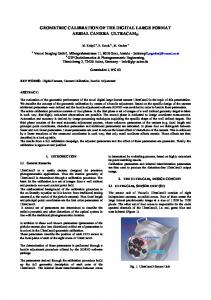
III. POINT PAIR ACQUISITION To obtain the intrinsic and extrinsic parameters of the IR camera, the 3-D and 2-D image coordinates of the light points in the calibration board should first be determined. The point pairs can then be constructed from these 3-D and 2-D coordinates. Next, the parameters of the IR camera can be approximated if sufficient point pairs are obtained. Therefore, a trinocular vision system is constructed to obtain these point pairs. A. Constructing the Calibration Platform The trinocular vision system for calibrating the IR camera consists of two color cameras and an IR camera, as shown in Fig. 1. The two color cameras compose a binocular vision system that captures the 3-D coordinates of the feature points on the calibration pattern. The left color camera coordinate with as its three coordinate axes is system established. The and axes lie on the image plane, the axis is aligned with the optical axis of the left camera lens, and is attached to the optical center of the left camera. the origin The right color camera coordinate system with and origin and the IR camera coordinate system with and origin are established similar to the left camera. The global coordinate system with and origin is determined by the two color cameras, where is attached on coincides with the direction of the vector from to is used to make the three axes coplanar, and is calculated using the right-hand rule. As a result, the four coordinate systems are constructed. If an in in , and arbitrary point is expressed by in in , the relationships between , and are expressed as (1) (2) (3) and are the transformation from to where and are the transformation from to , and and are the transformation from to . Let the intrinsic parameters of the two color cameras be and , respectively. A checkerboard pattern produced by a liquid crystal display (LCD) is used to calibrate the two color cameras. This pattern is placed in different positions with different poses in the field of view and is captured by the two cameras. Then, the intrinsic parameters are calculated from the captured images using the camera calibration toolbox for Matlab and , which char[20]. Then, the two pose parameters acterize the relative location of with respect to , are obtained using a stereo calibration [20]. Based on the relationships of these coordinate systems, the extrinsic parameters , and can be computed, which were discussed in detail
YANG et al.: GEOMETRIC CALIBRATION OF IR CAMERA USING TRINOCULAR VISION
3799
Fig. 1. Schematic of a trinocular vision system for calibrating IR camera.
(4) and are the and derivatives of an image , rewhere spectively; is a Gaussian filter; is the tolerance paramin our implementation) to avoid the numereter (set to ical problem. The candidate corners are selected as the light points through non-maximum suppression. The subpixel locais estimated using the quadratic approximation tion given by
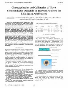
Fig. 2. Calibration board of IR camera.
in the previous work [21]; however in this step.
and
cannot obtained
(5)
B. Extracting the Image Points In the color camera calibration, the checkerboard calibration pattern is produced from an LCD; however, this pattern is not sensitive to the IR camera. To design a pattern sensitive to both color and IR cameras, a black plastic board with 25 holes is used as the calibration board, as shown in Fig. 2. Miniature bulbs are attached to the back of the calibration board. When the board is powered on, heat and light are emitted by the bulbs and pass through the holes to form points on the board to be synchronously captured by the IR and color cameras. By positioning the calibration board in the field of view, three images are captured by the two color cameras and the IR camera, respectively. In each image, the 25 light points are arranged in 5 rows and 5 columns, and are extracted using a semi-automatic method. The corners’ pixel coordinates of the four corners of the light points in the image are recorded by clicking the four corners of the light points clockwise or counter-clockwise. Let . A rectangle region with a corner coordinate be four vertices is defined, where ensures the region encompassing the light point. Then, the subpixel location of the light point is detected in the region using the Harris corner detector [22], which is strongly invariant to rotation, scale, illumination variation, and image noise. In the implementation of the Harris corner detector, the corner measure is given by
(6) where is the coordinate of the pixel point in the region and is the corner measure of the pixel at . Similarly, four extracted subpixel locations are linked to a quadrangle that can be partitioned to a 5 5 grid. The grid points are not exactly on the subpixel locations of the light points; rather, they are close to the corresponding light points, because of the camera lens distortion. If a proper is used, all of the light points are covered by the corresponding rectangle region. Thus, the subpixel locations can be accurately detected using this method. Therefore, a light point on the calibration board can be captured using the three cameras and its three subpixel coordinates , and are obtained on the images captured by the left, right, and IR cameras, respectively. C. Computing the Point Pairs Let , and be the coordinates of the three images captured from and intrinsic and extrinsic parameters of the two color cameras are acquired. From [21], the ideal normalized can be obtained from . A line equation, point calculated in according to (1), is given by (7)
3800
JOURNAL OF LIGHTWAVE TECHNOLOGY, VOL. 29, NO. 24, DECEMBER 15, 2011
where is the coordinate of in the global coordinate system, and is an arbitrary value. Similarly, from (2), another line equation with respect to ’ can be obtained as
of are less than , this procedure is terminated, and the outliers are removed in .
(8) Because is simultaneously captured by the two color cameras, satisfies (7) and (8). Thus, it is calculated using these two equations, as detailed in [21]. Here, and , which are obtained from the same , form a point pair. As shown in Fig. 2, the 25 point pairs are obtained from the three images simultaneously captured by the three cameras. The abundant point pairs can be obtained to calibrate the IR camera by moving the calibration board in the field of view.
IV. CALIBRATION PROCEDURE Supposing points are removed as outliers from to con. The struct a new point set corresponding subpixel points can then be obtained from the IR camera because the relationship between the 3-D and subpixel points in the IR images is known. and . First, if the lens Let distortion of the IR camera is not considered, the relationship between and is given by
D. Outlier Removal Because of some factors, such as manufacturing error in the calibration boards of the color and IR cameras, a few of point pairs are incorrectly extracted and directly affect the calibrating accuracy. Thus, these point pairs should be removed before calibrating the parameters of the IR camera. If the calibration board is successfully captured by the three can be obtained in . If the calicameras, 25 3-D points bration board is moved to another position, 25 other points , whose relative positions with each other are invariable, can be and can be expressed obtained. The relationship between as
(13)
Let . The following matrices can be constructed as
(14)
(9) where is a 3 3 orthonormal rotation matrix, is a 3 25 and are 3 25 matrices. Here, translation matrix, and is obtained by subtracting the mean value of each row from , and the 3 3 covariance matrix can be obtained as follows: (10) A 3 3 unitary matrix , a 3 3 diagonal matrix , and a unitary matrix V are then obtained by computing the singular and are given value decomposition (SVD) of . Thus, by (11) (12) Then the 3 1 translation vector is obtained by meaning the . The point set is 25 rows of positions, and obtained by moving the calibration board to is arbitrarily chosen from as the initial template. The and from to can be computed corresponding using (9)–(12). Next, is computed from , and from (9). Thus, the point set transforms to a new point set , and is computed by averaging all in as a template. The distance between a point in and the corresponding point in is computed. If is greater than the user-specified threshold , the corresponding point in is removed as an outlier. After checking all should be recomputed using the remaining the points in corresponding to the remained points points in . When all
(15) A linear equation can then be obtained using the matrices as
and (16)
is obtained from (16) using the least mean square If can be re(LMS) algorithm [23], [24]. So a 3 4 matrix constructed using from (13) and can be decomposed to the following: (17) where is a 3 3 matrix, is a 3 1 vector, and is computed . Sets , and are the three rows of . using The intrinsic parameters are computed as follows:
(18)
, and is determined by making where Thus, the intrinsic matrix can be obtained as
and
positive.
YANG et al.: GEOMETRIC CALIBRATION OF IR CAMERA USING TRINOCULAR VISION
3801
(19) . Therefore, the transand the rotation matrix . Without considering the lens dislation vector tortion, the initial intrinsic and extrinsic parameters can be obtained. However, a nonlinear method is necessary to further optimize these initial results. Assuming that all of the intrinsic and extrinsic parameters is reprohave been obtained, a 3-D point jected to the image plane to obtain the image coordinate and its real image coordinate captured by camera is . The object function is written as (20)
Fig. 3. Captured images from the calibration board: (a) an image captured by a color camera; (b) an image captured by the IR camera; (c) and (d) are the 3-D display with respect to the gray of (a) and (b), respectively.
where . The points and are obtained first by using the Levenberg-Marquardt algorithm [25] to optimize (20). V. EXPERIMENTAL RESULTS The positions of the IR camera (GUIDEIR, IR112) and the two color cameras (SONY, SSC-E453P) are shown in Fig. 1. The resolutions of the IR and color cameras are 240 320 and 768 576, respectively. An LCD checkerboard (Philips 150S5) with a checker size of 23.76 mm 23.76 mm is designed to calibrate the two color cameras. The cameras capture this checkerboard in different poses in the field of view, and 20 images are , and obtained to calculate the parameters of the two color cameras using the camera calibration toolbox for MATLAB [20]. The parameters , and are also obtained using the method in [21]. Hence, the two color cameras are positioned based on the global coordinate system. In Fig. 3, the bulbs on the calibration board produce heat and light when the board is powered on. The heat and light pass through the holes on the board and are simultaneously captured by the IR and color cameras. Figs. 3(c) and (d) show that the gray in the position of the holes is significantly larger than that in the surrounding regions. This pattern can be captured not only by the IR camera, but by the color cameras as well. The luminance of the light points in the images is sufficient to accurately extract the subpixel coordinates of the light points. The calibration board is captured by the three cameras to form three images, after which the subpixel coordinates of the light points are extracted, as shown in Fig. 4. The relationships of the three subpixel points on the three images are also determined in the subpixel extraction. The coordinates of the 3-D points are computed using the reconstruction algorithm in [21]. All the 3-D points are obtained according to the algorithm, as shown in Fig. 5(a), and the 20 positions of the calibration board are subshown in Fig. 5(b) is sequently reconstructed. The template calculated using (9)–(12) after the iterations. The and from each to are then obtained, and is rotated and to form . If the distance betranslated to the position of tween a point and the corresponding point is
Fig. 4. Performance of subpixel coordinates of light points: (a) and (c) subpixel coordinates of the light points extracted from the images by the left and right cameras, respectively; (b) those by the IR camera.
Fig. 5. 3D reconstruction result of the calibration board: (a) 3-D results of the calibration board on 20 positions; (b) the template calibrated from (a).
greater than the 1 mm threshold, the point is removed as an outlier. After this operation, 24 points are removed and 476 points remain. As Fig. 4 shows, the correspondences of the subpixel points in the three images have been obtained using the semi-automatic method of subpixel extraction. The correspondences between the 3-D points in Fig. 5(a) and the subpixel points in the IR images, such as those in Fig. 4(b), have also been determined. During the outlier removal, 24 point pairs are removed and 476 point pairs are retained. Because 476 points have been obtained in the 3-D space, the corresponding 476 subpixel points in the IR images are acquired. The initial parameter values are then
3802
JOURNAL OF LIGHTWAVE TECHNOLOGY, VOL. 29, NO. 24, DECEMBER 15, 2011
of the IR camera. The reprojection error after the linear calculation is 0.6 mm. A nonlinear optimization is then conducted. The reprojection error is reduced to 0.5895 pixels, which is greater than 0.5722 pixels obtained after the outlier removal. Therefore, the outlier removal is necessary for this process. VI. DISCUSSION AND CONCLUSION
Fig. 6. Nonlinear optimization. (a) The changes in the reprojection error in the iterations. (b) Reprojection results; + represents the light points extracted from the IR image; o represents the points projected from the 3-D points to the image using the calibration parameters. TABLE I INTRINSIC PARAMETERS OF THE IR CAMERA
calculated using (13)–(18). These initial parameters used to reproject the 3-D points to the image plane to form a new subpixel points set. The mean distances between these new points and the subpixel points in the images are regarded as reprojection errors in (20) and are used to evaluate the accuracy of the calibration. The calculated reprojection error is 0.5881 pixels. To accurately obtain the parameters of the IR camera, a nonlinear optimization is used to minimize (20). The initial parameters are used as the initial values for the optimization. When mm, the the change in the focal length becomes less than iteration is terminated. After 1340 iterations, the change in the focal length reaches mm. This process is also shown in Fig. 6(a). Eventually, the parameters of the IR camera are obtained, as listed in Table I. In Table I, the relative error of the focal length is 0.13%. In contrast, Wang et al. [26] used identical products to calibrate a visible camera and produced relative errors of up to 4.71% and 3.91% in the directions of the two axis, respectively. Drareni et al. [27] used a planar object to calibrate a linear camera and produced a relative error of 0.57%. Therefore, the proposed method can accurately obtain the parameters of the IR camera. Next, the parameters in Table I are used to reproject the 3-D points to the IR image plane; the reprojection error reaches 0.5722 pixels. This shows that the lens distortion is necessary to calculate the 3-D coordinates for more accurate measurements. In Fig. 6(b), all of the 3-D points have been effectively reprojected to the 2-D IR image and match with the corresponding subpixel points, which have been extracted from the IR images shown in Fig. 4(b). Th us, these parameters are able to meet the demands of 3-D IR imaging. To further prove the importance of outlier removal, 500 points are used to calculate the parameters
The visible camera calibration has been investigated for many years, and corresponding methods have continuously emerged. Visible calibration patterns have regular shapes, and their geometric sizes are known before calibration. However, these patterns cannot be sensed by an IR camera; thus, these patterns are unsuitable to calibrate an IR camera. Therefore, a pattern that can be captured by an IR camera is necessary to be designed for calibrating the IR camera. In the proposed approach, a plastic board with 25 holes is designed and 25 miniature bulbs are arranged at the back of this board. Two visible cameras are used to aid in the calibration of the IR camera. The miniature bulbs emit heat and light, which simultaneously captured by the visible and IR cameras. The two visible cameras compose a binocular subsystem that obtains the 3-D coordinates of the light points on the board. The corresponding image coordinates are also obtained by the IR camera. After linear computation and nonlinear optimization, the intrinsic and extrinsic parameters of the IR camera are obtained. The image coordinates extraction plays an important role in determining the accuracy of calibration. The miniature bulbs improve the consistencies of the light points on the board. The gray distributions of the light points on the visible and IR images are used to extract their subpixel coordinates. The results show that the calibration board is suitable for the calibration of the IR camera. The two visible cameras are accurately calibrated using an LCD checkerboard pattern, and the acquired 3-D coordinates of the light points have high precisions. From the analysis of Fig. 5, the geometric parameters of the light points, such as the distance of two neighboring points, in different positions are identical; however, the experimental results show that the removal of some outliers because to the manufacturing error of the calibration board, such as the irregularity of the holes and misplaced bulbs at the back of the board. Thus, these outliers should be removed before calibration. Furthermore, manufacturing a more accurate calibration board is recommended to further improve the accuracy of the obtained parameters. In addition, arranging all of the light points on their presupposed positions on the calibration board would be impossible because of the manufacture error. Thus, the algorithms based on the known patterns with regular sizes have not been directly used in this study; instead, a corresponding calibration algorithm based on the 2-D and 3-D point pairs is used. Finally, the produced relative error of the focal length with a value of 0.13% is acceptable because only the current methods of calibrating a visible camera can achieve this accuracy and these methods are widely used in applications. The intrinsic and extrinsic parameters of the IR camera have been accurately obtained using the trinocular vision. Even though the position accuracy of the light points on the calibration board is less than that of the LCD pattern, the acceptable calibration results are obtained using the proposed method.
YANG et al.: GEOMETRIC CALIBRATION OF IR CAMERA USING TRINOCULAR VISION
REFERENCES [1] E. Y. K. Ng and R. U. Acharya, “Remote-sensing infrared thermography reviewing the applications of indoor infrared fever-screening systems,” IEEE Eng. Med. Biol., vol. 28, no. 1, pp. 76–83, 2009. [2] L. J. Jiang, E. Y. K. Ng, A. C. B. Yeo, F. P. S. Wu, W. Y. Yau, J. H. Chen, and Y. Yang, “A perspective on medical IR imaging,” J. Med. Eng. Technol., vol. 29, no. 6, pp. 257–267, 2005. [3] J. H. Tan, E. Y. K. Ng, U. R. Acharya, and C. Chee, “IR thermography on ocular surface temperature: A review,” Infrared Phys. Technol., vol. 52, no. 4, pp. 97–108, 2009. [4] X. Ju, J. C. Nebel, and J. P. Siebert, “3D thermography imaging standardization technique for inflammation diagnosis,” in Proc. SPIE, Beijing, China, 2004, pp. 5640–5646. [5] S. Colantonio, M. Benvenuti, M. G. D. Bono, G. Pieri, and O. Salvetti, “Object tracking in a stereo and IR vision system,” Infrared Phys. Technol., vol. 49, no. 3, pp. 266–271, 2007. [6] X. Yang, Y. Huang, and F. Gao, “A simple camera calibration method based on sub-pixel corner extraction of the chessboard image,” in Proc. IEEE Int. Conf. ICIS, Xiamen, China, 2010, pp. 688–692. [7] L. Song and M. Wang, “High precision camera calibration in vision measurement,” Opt. Laser Technol., vol. 39, no. 7, pp. 1413–1420, 2007. [8] X. Q. Meng and Z. Y. Hu, “A new easy camera calibration technique based on circular points,” Pattern Recogn., vol. 36, no. 5, pp. 1155–1164, 2003. [9] X. Chen and J. Xi, “Accurate calibration for a camera-projector measurement system based on structured light projection,” Opt. Lasers Eng., vol. 47, no. 3–4, pp. 310–319, 2009. [10] R. Y. Tsai, “A versatile camera calibration techniaue for high-accuracy 3-D machine vision metrology using off-the-shelf TV cameras and lenses,” IEEE J. Robot. Autom., vol. 3, no. 4, pp. 324–344, 1987. [11] J. Weng, P. Cohen, and M. Herniou, “Camera calibration with distortion models and accuracy evaluation,” IEEE Trans. Pattern. Anal. Mach. Intell., vol. 14, no. 10, pp. 965–980, Oct. 1992. [12] Z. Zhang, “A flexible new technique for camera calibration,” IEEE Trans. Pattern. Anal. Mach. Intell., vol. 22, no. 11, pp. 1330–1334, Nov. 2000. [13] H. Bacakoglu and M. S. Kamel, “A three-step camera calibration method,” IEEE Trans. Instrum. Meas., vol. 46, no. 5, pp. 1165–1172, May 1997. [14] J. Heikkilä and O. Silvén, “A four-step camera calibration procedure with implicit image correction,” in IEEE Proc. CVPR, San Juan, Puerto Rico, 1997, pp. 1106–1112. [15] D. Iwai and K. Sato, “Optical superimposition of IR thermography through video projection,” Infrared Phys. Technol., vol. 53, no. 3, pp. 162–172, 2010. [16] S. Laguela, H. Gonzalez-Jorge, J. Armesto, and P. Arias, “Calibration and verification of thermographic cameras for geometric measurements,” Infrared Phys. Technol., vol. 54, no. 2, pp. 92–99, 2011. [17] Q. Lv, G. Hou, Z. Luo, Q. Lv, and G. Hou, “Camera calibration method in reverse engineering,” in IEEE Int. Conf. Automation Logistics, Jinan, China, 2007, pp. 2936–2939. [18] M. Bauer, D. Grie{\ss}bach, A. Hermerschmidt, S. Krüger, M. Scheele, and A. Schischmanow, “Geometrical camera calibration with diffractive optical elements,” Opt. Exp., vol. 16, no. 25, pp. 20241–20248, 2008. [19] J. Heikkilä, “Geometric camera calibration using circular control points,” IEEE Trans. Pattern Anal. Mach. Intell., vol. 22, no. 10, pp. 1066–1077, Oct. 2000. [20] J.-Y. Bouguet, Camera Calibration Toolbox for Matlab. [Online]. Available: http://www.vision.caltech.edu/bouguetj/calib_doc/ [21] R. Yang, S. Cheng, and Y. Chen, “Flexible and accurate implementation of a binocular structured light system,” Opt. Laser Eng., vol. 46, no. 5, pp. 373–379, 2008. [22] C. Harris and M. Stephens, “A combined corner and edge detector,” in Proc. 4th Alvey Vision Conf., Manchester, U.K., 1988, pp. 147–151. [23] Y. I. Abdel-Aziz and H. M. Karara, “Direct linear transformation into object space coordinates in close-range photogrammetry,” in Proc. Symp. Close-Range Photogrammetry, Urbana, IL, 1971, pp. 1–18. [24] O. D. Faugeras and G. Toscani, “Camera calibration for 3-D computer vision,” in Proc. Int. Workshop Mach. Vis. Mach. Intelli., Silken, Japan, 1987, pp. 240–247.
3803
[25] J. J. More, , G. A. Watson, Ed., “Lecture notes in mathematics 630: Numerical analysis,” in The Levenberg-Marquardt Algorithm: Implementation and Theory. New York: Springer-Verlag, 1977. [26] R. Wang, G. Jiang, L. Quan, and C. Wu, “Camera calibration using identical objects,” Mach. Vis. Appl., pp. 1–9, 2011. [27] J. Drareni, S. Roy, and P. Sturm, “Plane-based calibration for linear cameras,” Int. J. Comput. Vis., vol. 91, no. 2, pp. 146–156, 2011.
Rongqian Yang received the B.S. degree in electronic instrumentation and measurement from Nanchang Institute of Aeronautical Technology, Nanchang, China, in 2001, the M.S. degree in communication and information systems from Jinan University, Guangzhou, China, in 2005, and the Ph.D. degree in biomedical engineering from Shanghai Jiao Tong University, Shanghai, China, in 2009. He is a Lecturer from the Department of Biomedical Engineering, South China University of Technology, Guangzhou, China. His main research areas include machine vision and biomedical instrument.
Wei Yang received the B.Sc. degree in automation from Wuhan University of Science and Technology, Wuhan, China, in 2001 and the M.Sc degree in control theory and control engineering from Xiamen University, Xiamen, China, in 2005, and Ph.D. degree in biomedical engineering from Shanghai Jiao Tong University, Shanghai, China, in 2009. He is a Lecturer from the School of Biomedical Engineering in Southern Medical University, Guangzhou, China. His main areas include image feature extraction, pattern recognition, and computerized-aid diagnosis.
Yazhu Chen received the B.S. degree in electrical engineering from Shanghai Jiao Tong University, Shanghai, China, in 1962. She is an academician at the Chinese Academy of Engineering, Beijing, China, and a distinguished professor in the Department of Biomedical Engineering, Shanghai Jiao Tong University, Shanghai, China. Her main research areas are multi-element array ultrasound hyperthermia systems, high-intensity focused ultrasound therapy technology, real-time medical information digital processing, 3-D medical image processing, and automatic control and electric technology. Ms. Chen was a recipient of the State Science and Technology Award (First Prize) in 1987 for being a pioneer in the field of noninvasive medical technology.
Xiaoming Wu received the B.S. degree in industrial automation from Chongqing University, Chongqing, China, in 1977 and the Ph.D. degree in biometrics from Chongqing University, Chongqing, China, in 1996. He is a professor in the Department of Biomedical Engineering, South China University of Technology, Guangzhou, China. His main research areas are biomedical information detection, biomedical instruments, and medical imaging processing.