(GDML) is a specialized XML-based language designed as an .... to Document Type Definition (DTD) files specifying the legal building blocks of an XML ...
SLAC-PUB-12301 January 2007
Geometry Description Markup Language for Physics Simulation and Analysis Applications Radovan Chytracek, Jeremy McCormick, Witold Pokorski, and Giovanni Santin
Abstract—The Geometry Description Markup Language (GDML) is a specialized XML-based language designed as an application-independent persistent format for describing the geometries of detectors associated with physics measurements. It serves to implement “geometry trees” which correspond to the hierarchy of volumes a detector geometry can be composed of, and to allow to identify the position of individual solids, as well as to describe the materials they are made of. Being pure XML, GDML can be universally used, and in particular it can be considered as the format for interchanging geometries among different applications. In this paper we will present the current status of the development of GDML. After having discussed the contents of the latest GDML schema, which is the basic definition of the format, we will concentrate on the GDML processors. We will present the latest implementation of the GDML “writers” as well as “readers” for either Geant4 [2], [3] or ROOT [4], [10]. Index Terms—Detector, GDML, Geant4, geometry, root, simulation.
I. INTRODUCTION
T
HE geometry description is the essential part of every Monte Carlo physics simulation application. It is one of the most “detector specific” element of the program and usually it is the most tedious to implement. At the same time it is often the case that the same geometry description needs to be used in several applications, either different simulation engines (for the purpose of physics validation and comparison) or other applications like visualization, reconstruction, analysis, etc. Those applications often come with their native, different geometry description formats, which forces users to either re-implement their geometry for each of the applications or to come up with automatic conversion mechanisms. It is indeed the case that users rarely implement their geometries in one of the simulation toolkits geometry formats. They usually come up with their own formats, which prove to be more flexible (often are XML-based) and allow re-use of the geometry in the different parts of the event processing chain. The potential drawback of such a solution, however, can be the fact that the geometry descriptions become strongly linked with the experiments’ software frameworks and therefore cannot be easily exported and used in stand-alone applications.
R. Chytracek and W. Pokorski are with CERN, CH-1211 Geneva 23, Switzerland. J. McCormick is with the Stanford Linear Accelerator Center (SLAC), Menlo Park, CA 94025 USA. G. Santin is with the European Space Agency (ESA), NL-2200 AG Noordwijk, The Netherlands.
It seems justified, therefore, to propose a geometry description language which would allow an application-independent way of implementing new geometries and provide and exchange format for the already existing geometries. The Geometry Description Markup Language (GDML) has been developed as an application of XML. This option provides a simple reading and writing mechanism, as well as extensibility. XML is a widely used application independent format. Moreover, as GDML is meant to describe geometry data, the choice of a markup rather then procedural language seems to be natural. The fact that a GDML file can be easily edited using any text editor, is also a big advantage as it allows to easily introduce any changes in the particular geometry description. The sections of this paper are organized as follows. We start with a very brief general introduction to the detector modeling domain and then we move to the more GDML-specific issues. We introduce the different components the GDML machinery is made of. We concentrate on discussing more in detail the structure of GDML schema as well as the GDML readers and writers. Finally, before concluding, we demonstrate how GDML can be used, and illustrate it with a few examples. II. DETECTOR GEOMETRY DESCRIPTION BASICS The detector geometry description consists of providing all the data necessary to simulate and reconstruct the passage of the particles through the detector. In the general words the information one has to provide is, what is the geometrical hierarchy (the geometry tree) of the detector volumes, what are the solids (shapes) that the volumes are made of and what are the materials the different parts are made of. The common way of representing the geometry tree is to use the concepts of logical and physical volumes. The logical volumes are unpositioned objects described by the solid they are made of and the material. Moreover, the logical volumes can have “daughter” volumes. The “daughter” volumes are physical volumes, which means that they are concrete “placements” of some other logical volumes within the given logical volume. The positioning of the physical volumes is done in the local (the one of the “mother” volume) coordinate system and in general can consist of a translation and a rotation. This hierarchical approach is a very efficient way of describing the detector geometry for the purpose of the simulation and it is also used in GDML. The basic building block for the detector geometry description are geometrical solids like boxes, spheres, tubes, cones, etc. When constructing the geometry one specifies the dimension of
Submitted to IEEE Trans.Nucl.Sci. Work supported in part by the US Department of Energy contract DE-AC02-76SF00515
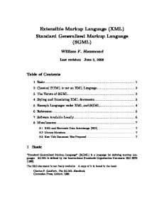
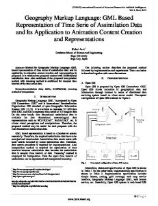
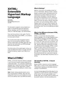
Fig. 1. GDML components.
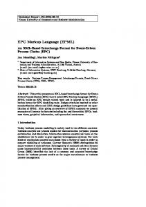
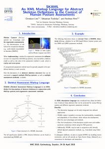
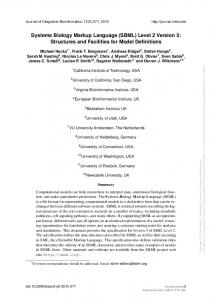
the particular solid. More advanced solids can be made by combining several basic solids using boolean operations like a union, a subraction and an intersection. Each physical volumes is made of a particular material. The materials can be either composed of one chemical element (like Aluminium for instance) or can be mixtures of several different elements. Mixtures of several different materials are often also convenient to use. In some particular cases, materials made of different isotopes of the same element need to be defined. III. GDML COMPONENTS GDML consists of two elements. An XML definition part containing the set of rules and the list of the legal elements to be used in constructing any GDML document, and the GDML generating and processing code. The structure of the GDML document is defined through a set of XML Schema Definition (XSD) files which we call the GDML schema. These files are an XML-based alternative to Document Type Definition (DTD) files specifying the legal building blocks of an XML document. Any GDML geometry file must be valid with respect to the GDML schema. The GDML file itself, can be either written by hand (in case GDML is used as the primary geometry source) or generated automatically out of the application specific “in-memory” geometry tree using one of the GDML “writers” called by the user application (when GDML is used as an exchange or persistency format). The GDML reader is responsible for parsing the GDML file and creating the in-memory representation of the geometry tree specific for the user application. The overall picture of different GDML components is shown in Fig. 1. IV. GDML SCHEMA The GDML schema is a set of XSD files which define the structure of the GDML document and its legal elements. The general structure of the GDML file can be seen on Fig. 2. One can distinguish there five parts, each holding specific type of data. block contains numerical The values of different constants, positions and rotations that will be used later on in the geometry construction.
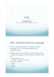
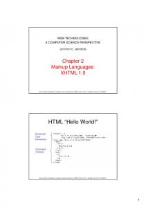
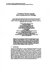
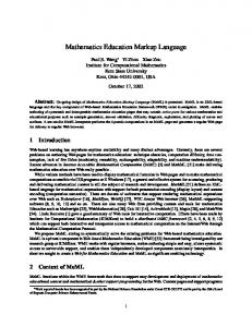
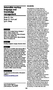
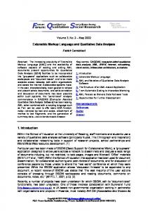
block contains definiThe tions of all the materials used in the given geometry. The supported forms are simple materials which are made from one element as well as mixtures. Mixtures can be composed on the basis of fraction of mass or atom count. block is the collection of all The solid definitions which are used in the given geometry description. The presently supported solids are box, sphere, tube, cone, polycone, parallepiped, trapezoid, torus, polyhedra, hyperbolic tube, elliptical tube and ellipsoid. New solids are constantly being added to that list. Composite solids made using boolean operation (union, subtraction, intersection) are also supported. block contains the The actual implementation of the geometry tree together with the assignment of solids and materials. The hierarchy of volumes is defined by specifying the daughter volumes (physvol) positioned inside a volume. Constructions like assembly volumes, reflections, replicas and divisions are possible. There is also basic support for parameterized volumes which will be extended in the future. block serves to specify the Finally, the top volume of the geometry tree. It is possible to define several “setups” within one file, allowing to test different subparts (or different configurations included in the same file) of the geometry tree without changing the GDML file. We would like to note here that the initial implementation of the GDML schema was strongly inspired by the Geant4 geometry classes. Additional elements have been added later, some of them not supported by Geant4 but existing in the ROOT geometry package. V. GDML READER AND WRITER The role of the GDML reader is to parse the GDML file, validate it against the GDML schema (unless the validation is not enabled) and create the in-memory representation of the geometry specific for the given application. The design of the reader (see Fig. 3) is such that most of the processing is done within an application-independent XML engine based on the SAX parser [5]. The instantiation of the actual geometry objects is done by a light application-specific binding. The user interacts only through a very simple interface which returns the pointer to the top volume of the geometry tree with all the XML processing hidden. The presently available bindings are for Geant4 [2], [3] and ROOT [4], [10] geometry models. Due to the modularity of the design, it would be straightforward to add any more bindings if required in the future. The GDML writer functionality is to generate GDML files out of the “in-memory” geometry trees. The application-specific binding (see Fig. 4) scans the user defined geometry and prepares its representation in a application-independent way which can then be exported in the form of the GDML file. As in the case of the GDML reader, the application-specific binding is very light and most of the code is within the application-independent “document builder”. The user interaction with the GDML writer is also very simple and consists of calling the DumpGeometryInfo method, and passing the pointer to the top volume of the geometry tree as argument. The user does not deal directly with the actual generation of the XML file.
Fig. 2. GDML file.
Fig. 3. GDML reader.
Fig. 4. GDML writer.
Two implementation approaches are used for the GDML readers and writers. One uses C++ code and another uses Python together with specific Python bindings for particular C++ classes. The advantage of Python is that dealing with the XML parsing is more natural and easier than in C++ and therefore less code is needed. Moreover, Python turns out to be
a very convenient tool for interfacing different applications together. It provides a nice environment for interactive simulation and analysis. The C++ language have been used for the implementation of the GDML reader and writer for Geant4. They are used for Geant4 C++ applications, where GDML is used as geometry source or when the user wants to export the geometry from his native Geant4 application. The GDML reader and writer for ROOT have been implemented in Python. It uses PyROOT [4], [10] binding for ROOT classes. As mentioned in the previous paragraph, the choice of Python for that implementation significantly reduced the length of the processing code. Moreover, accessing ROOT from Python makes the integration with other applications easier and more interactive. The GDML reader for Geant4 has also been implemented in Python. It uses the Reflex [4], [10] tool for creating dictionary for the Geant4 classes which is then loaded into ROOT and allows interaction with those classes from the Python prompt. Such an approach allows to run interactively Geant4 and ROOT from Python using the same GDML file as geometry source. VI. USING GDML In this section we will briefly describe the way to use GDML readers and writers. We start with the GDML writer for Geant4. The only thing needed to export the geometry in the form of the GDML file is the pointer to the top volume of the geometry tree which is then used as argument for calling the appropriete method of the writer. This can be done for instance in one of the Geant4 “user actions” once the geometry has been closed. The user needs to instantiate the writer giving the name of the schema file and the name of the output file as arguments. Then the “DumpGeometryInfo” method must be called
G4GDMLWriter writer(“gdml.xsd”, “geo.gdml”); writer.DumpGeometryInfo(g4worldvolume);
The GDML file is then generated and saved on the disk.
To use the GDML reader for Geant4, the procedure is the following. First, one has to instantiate, initialize and configure file should correSAXProcessor, where spond to the GDML file to be read
from math import * from units import * import writer import ROOTwriter
SAXProcessor sxp;
retrieving the top volume of the geometry tree
sxp.Initialize(); ProcessingConfigurator config; config.SetURI(“mygeometry.gdml”);
topV = ROOT.gGeoManager.GetTopVolume()
and instanciating the writer (with the argument being the name of the output file)
sxp.Configure(&config);
and then one has to run the parsing and retrieve the pointer to the top geometry volume gdmlwriter = writer.writer(‘geo.gdml’) binding = sxp.Run();
ROOTwriter.ROOTwriter(gdmlwriter)
fWorld = (G4VPhysicalVolume *) GDMLProcessor::GetInstance()0
>
GetWorldVolume();
This can, for instance, take place in the method of class where the top volume the is returned. To use Python writers and readers, the procedure is very similar. We start here with the discussion of the GDML reader for ROOT. Assuming we have imported the ROOT module into Python and loaded the geometry library, we need just to import the generic XML parser and the GDML handler
We are now ready to export the geometry data. We start with the materials
matlist = geomgr.GetListOfMaterials() binding.dumpMaterials(matlist)
then the solids
shapelist = geomgr.GetListOfShapes() binding.dumpSolids(shapelist)
and the geometry tree import xml.sax import GDMLContentHandler
gdmlwriter.addSetup(‘default’, ‘1.0’, topV.GetName())
having done that, we can now instantiate the GDML handler and parse the file
gdmlhandler =
binding.examineVol(topV)
With all the data provided to the write we can now export the geometry in the form of a GDML file
GDMLContentHandler.GDMLContentHandler() xml.sax.parse(‘geo.gdml’, gdmlhandler)
The top volume of the geometry tree is now available from the handler:
topVolume = gdmlhandler.WorldVolume()
and can be passed to the ROOT geometry manager. The procedure for using the GDML writer for ROOT is the following. We assume that we have imported the ROOT module into Python and that the TGeo geometry that we want to export has been loaded into memory. We start, therefore, with loading the necessary additional modules
gdmlwriter.writeFile()
which concludes the procedure. VII. EXAMPLES As mentioned in the introduction, GDML can play two roles. It can be the language for the geometry implementation or it can be the geometry interchange format. In the first case, the use of GDML allows flexible geometry implementation which can be modified or exchanged without the need to recompile the application. GDML has been, for instance, the choice for the geometry implementation for the Geant4 simulation application of the International Linear Collider detectors like SiD, GLD and LDC [6], [11]. It is also used in space research for missions like ConeXpress, JWST as well as radiation studies like GRAS [7].
Fig. 5. CMS detector visualized using ROOT from an automatically generated GDML file.
In the medical physics field, GDML was the geometry implementation choice for the radiation protection, radiotherapy and dosimetry studies [8], [9]. As far as the geometry interchange aspect of GDML is concerned, it proves useful for the LHC experiments, where physics validation of simulation toolkits is performed with the help of it. For instance, the original Atlas TileCal test-beam geometry is exported in the form of GDML files and then loaded into different stand-alone simulation applications allowing validation of particular aspects of the simulation toolkits. GDML is also proving very useful in interchanging geometries between Geant4 and ROOT. An example of that can be seen on Fig. 5 where the whole CMS detector has been visualized using the ROOT 3D graphics. In this case the original geometry, implemented using the CMS-specific detector description language, was first loaded into the CMS Geant4 application. Once the Geant4 geometry tree was fully instanciated in memory, the Geant4 GDML writer was called to export it in the form of the GDML file. That GDML file was then loaded into ROOT using the Python converter and then visualized. VIII. CONCLUSION GDML is an XML-based, application-independent detector geometry description language designed for the purpose of sim-
ulation applications as well as analysis. It can be used as the main geometry implementation format or it can play the role of an interchange format. The advantages of using GDML for geometry description implementation is the fact that it avoids hard-coding of the geometry, as well as it allows easy modifications and reconfiguration of the geometry used for the specific application. As far as geometry interchange format is concerned, GDML allows to extract the geometry description from experiment-specific frameworks and use them in generic application for the purpose of physics validation and comparison. It also allows to move geometries between Geant4 and ROOT for the purpose of visualization using ROOT 3D graphics. As far as the future developments are concerned, it is planned to further extend support for different solids available in Geant4, for instance the family of twisted solids recently introduced there. Work is also foreseen to enable modularization of GDML files in order to be able to load different subdetectors independently.
REFERENCES [1] R. Chytracek, “The geometry description markup language,” in Proc. CHEP 2001, Beijing, China, pp. 473–476. [2] S. Agostinelli, “Geant4: A simulation toolkit,” Nucl. Instrum. Methods Phys. Res. A, vol. A506, p. 250, 2003. [3] J. Allison et al., “Geant4 developments and applications,” IEEE Trans. Nucl. Sci., vol. 53, no. 1, pt. 2, pp. 270–278, Feb. 2006. [4] R. Brun and F. Rademakers, “ROOT—An object oriented data analysis framework,” in Proc. AIHENP’96 Workshop, Lausanne, Switzerland, Sep. 1996. [5] [Online]. Available: http://www.saxproject.org/ [6] J. McCormick, “Full detector simulation using SLIC and LCDD,” in Proc. SLAC-PUB-11418, Aug. 18, 2005, p. 5. [7] G. Santin, V. Ivanchenko, H. Evans, P. Nieminen, and E. Daly, “GRAS: A general-purpose 3-D modular simulation tool for space environment effects analysis,” IEEE Trans. Nucl. Sci., vol. 52, no. 6, pp. 2294–2299, 2005. [8] G. Guerrieri, “Development of Anthropomorphic Models for Radiation Protection and Radiotherapy,” Ph.D. dissertation, Univ. Genova, Genova, Italy, 2005. [9] R. Capra, S. Chauvie, Z. Francis, S. Guatelli, S. Incerti, and B. Mascialino, “Geant4 capabilities for microdosimetry simulation,” presented at the Radiation Protection and Dosimetry (Proc. Suppl.), 2006, submitted for publication. [10] R. Brun and F. Rademakers, “Root—An object oriented data analysis framework,” Nucl. Instrum. Methods Phys. Res. A, vol. A389, pp. 81–86, 1997. [11] J. McCormick, “Full detector simulation using SLIC and LCDD,” in Proc. Int. Linear Collider Workshop, Stanford, CA, Mar. 18–22, 2005.