Goal-Directed Modeling of Self-adaptive Software Architecture Shan Tang1, Xin Peng1, Yijun Yu2, and Wenyun Zhao1 1
School of Computer Science and Technology, Fudan University, Shanghai, China {tangshan,pengxin,wyzhao}@fudan.edu.cn 2 Department of Computing, The Open University, United Kingdom
[email protected]
Abstract. Today’s large-scale computing systems are deployed in open, changing and unpredictable environments. To operate reliably, such systems should be able to adapt to new circumstances on their own to get them running and keep them running. Self-adaptive software system has been proposed as a good solution for this demand. However, very few techniques are available to date for systematically building such kind of system. Aiming at this requirement, this paper presents a sound approach to derive a self-adaptive software architecture model from the requirements goal model in systematic way. At the same time, we illustrate our approach by applying it to a simplified on-line shopping system. Keywords: Goal model, Component, Software Architecture, Self-adaptive.
1 Introduction Nowadays, widespread popularization of internet and emergence of many application patterns such as pervasive computing and grid computing need to operate in open, changing and unpredictable environments. To operate reliably, such systems must have the capabilities of adaptability. Self-adaptive software systems can automatically take the correct actions based on the knowledge of what is happening in the system, guided by objectives and needs of stakeholders [14]. So, self-adaptive software has been proposed as a good solution for this demand. However, there is a troublesome step in the development process of self-adaptive software system which is transforming what we want the system to do (requirement analysis model) into a framework for how to do it (software architecture design model). Requirements specifications can be viewed as a contract between the customer and the software developers. Hence, they should be not only easy to understand by the software architects and engineers but also by the end-users (customers) [1]. Traditional requirement analysis approaches, such like those used in structured method and object-oriented method just describe the structure and behavior of the system from developers’ view, and do not contain the information that is interest to end-users. Therefore, those approaches are inadequate for transforming the requirement model to software architecture. Among all the kinds of requirements specifications, goal model are more near to the way end-users thinks and are easy to understand by all the stakeholders. So goal model becomes a hot research topic in requirement engineering domain [2,3,4]. T. Halpin et al. (Eds.): BPMDS 2009 and EMMSAD 2009, LNBIP 29, pp. 313–325, 2009. © Springer-Verlag Berlin Heidelberg 2009
314
S. Tang et al.
In current goal-based methodologies for developing software systems, requirement-level variability modeling, specifying and analyzing have been well understood and supported. However, their transition to self-adaptive software architecture remains vague, that makes the derivation for this kind of application system hard to achieve on the design level. Aiming at this problem, this paper proposes a promising approach to solve the problem existing approaches met. Specifically, in this work, the requirements model defines the stakeholder objectives in goals and sub goals. The structural view of the software architecture is obtained by converting each goal and subgoal to a corresponding component. The behavioral view of software architecture is defined in terms of FSM. The self-adaptive knowledge base of the component is designed as a part of component to collect the data, analyze it and make decisions according to the high-variability goal model. The approach to derive the self-adaptive software architecture model from the goal requirement specification model is very systematic and can be used for any self-adaptive software development. The rest of this paper is organized as follows: Section 2 introduces some background knowledge of requirements goal model; Section 3 presents our self-adaptive component model at first, then illustrates the derivation for self-adaptive software architecture model; in Section 4 some related works are discussed; finally, we conclude this paper and point out our future work directions in Section 5.
2 The Goal-Oriented Requirement Model In our approach, we specify our goal-oriented requirement model under the KAOS modelling framework. The KAOS (Keep All Objectives Satisfied) methodology has been developed by Axel et al. [19] for about ten years of research and experience in real projects. And it represents the state-of-the-art specification model for research on the goal-oriented requirement engineering. In this section we first revisit some key concepts and terminologies of the KAOS methodology which will be used later in this paper. Then we present an example of goal modelling. For more details on KAOS, readers can refer to [5,6,7]. KAOS is a goal oriented requirements specification language, and it defines four primary types of concepts: goal, agent, object and operation [7]. Goals are stakeholder objectives that the system should achieve. A goal model generally consists of one or more root goals, and each root goal is AND/OR decomposed repeatedly until every leaf-level goal is realizable by some individual agent assigned to it. If a goal G is AND/OR–refined into subgoals G1,…,Gn, then all/at least one of the subgoals must be satisfied for G to be satisfied. An OR-decomposition of a goal introduces a variation point, which defines alternative ways of fulfilling the goal. It is easy to verify that generally the number of variability represented by a goal model depends exponentially on the number of OR decompositions. The goal refinement process generates a goal refinement tree and the leaves may also be called requisites. The requisites that are assigned to the software system are called requirements, and those assigned to the interacting environment are called assumptions. Agents are active components such as humans, automated components that play some role assuring the goals satisfaction. Some agents define the software whereas the others define its environment.
Goal-Directed Modeling of Self-adaptive Software Architecture
315
On-line Shopping
Register/Login
……
Browse Merchandises
On-line Payment
Order Management
……
…… Bill Creating
Payment
……
Log
……
…… PayByCredit
PayByAlipay
Process Credit Card Form
Cash On Delivery
……
……
Legend:
Delivery
Show The Payment Result
goal
Agent
Refinement
Responsible
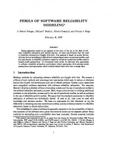
Fig. 1. Segment of the goal model for a simplified On-line Shopping System
Objects can either be entities (passive objects), agents (active objects), events (instantaneous objects), or relationships between objects. The state of the system is defined by aggregation of the states of its objects. Operations are actions performed by agents to achieve system goal by operationalizing a requirement. In general, an operation is represented by an input-output relation over objects and is used to define state transitions. Figure 1 shows an example of a goal model describing the requirements for a simplified On-line Shopping System. In this figure, AND-refinements have lines from each subgoal to the same blue circle. OR-refinements have lines from subgoals to different blue circles. For the sake of simplicity, the figure does not depict all the goal elements of this system. The formal KAOS specification of a goal is described by several fields. The first field Goal (Requirement or Operation) denotes the type of entity and name of the particular instance; the second field is the Concerns field, which is used to list the concepts that the entity uses, or is concerned with; the RefinedTo field contains the sub-goals and/or requirement into which the goal is refined; the Refines field refers to the goal refined by the entity being described; next, the InformalDef field describes the informal definition of the entity being described; the optional field FormalDef give the formal definition of the entity being described and can be represented in any formal notation, in this paper we adopt the linear temporal logic[12] to formalize this field. Take the “On-line Payment” goal shown in figure 1 for example, its corresponding formal KAOS specification is described as follows: Goal Achieve [On-line Payment] Concerns OrderNum, TotalCost, CreditCardNum, PayResult… Refines Achieve [On-line Shopping] RefinedTo Achieve [Bill Creating], Achieve [Payment], Achieve [Log] InformalDef We require the system to discount before carrying out pay if the customer is a VIP customer. FormalDef □( VIP ⇒ ( ¬ Pay Discount ))
∪
316
S. Tang et al.
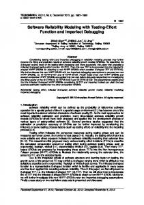
3 Self-adaptive Software Architecture Model Derivation In this section, we describe how to derive a self-adaptive software architecture model from goal models. Software architectures provide high-level abstractions for representing the structure, behavior of software systems. Therefore, the software architecture model consists of two design views: the first one is the structural view which is a macro view of a self-adaptive software system, specifying the overall topological structure and considering dynamic changes of the structure in various scenarios; and the second one is the behavior view which is a micro view of self-adaptation. A fundamental software engineering principle is to modularize a software system into a set of subsystems (i.e. modules, components) that have high cohesion and low coupling [8]. Thus, in this paper we specify a self-adaptive software architecture model in terms of the self-adaptive components. A component is an encapsulation of a computational unit and has interface to specify its provided services and required services. And the self-adaptive component extends the component concept to adapt the structural configuration and dynamic behavior of itself. For elaborating how to derive the self-adaptive software architecture model, we first introduce our selfadaptive component model. Then we explain how to derive the software architecture model from the goal model by mapping the goals in the goal decomposition tree to the components of the software architecture. 3.1 Self-adaptive Component Model Overview The structural model of a self-adaptive component is presented in figure 2. It is composed of a control center, several internal/external ports and the implementation body. In this paper we extend the component model which was proposed in our previous work [9] by adding an adaptation manager component into the control center. In this model, a component has a number of ports. Each port defines a logically separable point of interaction with its environment. A component explicitly states its provisions/requirements by its external provide/request ports. Three kinds of ports are
Component Control Center Adaptation Adaptation Manager Manager
Monitor
Analyzer
Planner (Goal-based Behavior Protocol)
Executor (FSMbased Control Flow)
Knowledge Base (Goal Model)
Switch valve
Implementation Body
Legend:
External Provide Port
External Request Port
Internal Port
Control Flow
Fig. 2. The structural model of a self-adaptive component
Goal-Directed Modeling of Self-adaptive Software Architecture
317
identified [9]: 1) External provide ports. They define how the environment can access the functionalities implemented by the component, and they are also the entries for other components to startup the control flow; 2) External request ports. They define how the component can access the functionalities provided by the environment. At the same time, they are the entries for the control flow to involve external service providers; 3) Internal ports: They are internal functional interfaces provided by the implementation body to fulfill external requests. Usually, after an external request is received, one or more internal ports will be involved in an execution of the control flow to complete the whole service process. Control center is separated from the component implementation to enforce component-level coordination on its external and internal ports according to the behavioral protocol. At runtime, usually, the control center will be activated by requests of other components on a provide port, then it will perform a series of interactions on internal ports and external request ports on the runtime control flow. In order to see whether and how well the self-adaptive component achieves its goal, it needs to monitor its managed element, collect the data, analyze it based on its knowledge (in our approach, we use goal model as the knowledge for component’s adaptation), plan changes to its behavior if necessary, and execute the plan. The monitor in the adaptation manager senses the environmental components. The analyzer compares event data against patterns in the knowledge base to diagnose symptoms. The planner interprets the symptoms and devises a plan which is a goal-based behavior protocol. And the executor executes the FSM-based control flow which is translated from the goal-based behavior protocol. The switch valve associates one external request port of one component with two or more alternative external provide ports of other components. Therefore, a switch represents alternative bindings among interaction ports. The implementation body encapsulates computation logic of the component and exposes some internal ports for the control center. 3.2 Structural Model Derivation Now, we focus on using goal models to derive self-adaptive software architecture that can accommodate many/all possible functionalities that fulfill stakeholder goals. This is possible because our goals models are extensions of AND/OR graphs, with OR decompositions introducing alternatives into the model. The space of alternatives defined by a goal model can be used as a basis for designing self-adaptive software system (i.e., self-configuring system). In this paper, the structural model of a software system is defined by components and their bindings through their external provide/request ports. In general, an external request port of a component in the system must be bound to exactly one external provide port of another component. We achieve the alternative bindings of ports by introducing the “switch valve” component. In the most straightforward derivation case, a software component is derived from a goal as follows: for each functional goal, we create a corresponding component to achieve this goal. Specifically, the root goal node corresponds to the whole software system. The leaf-level goal nodes correspond to the actual physical software components. Whereas, the higher-level goal nodes are not directly associated with physical software components, but are used to orchestrate
318
S. Tang et al.
the lower-level nodes. However, these derivation rules are not enough for designing large-scale software systems. To derive the structural model of a software architecture systematically, we adopt a more formal approach in which we take an AND/OR goal decomposition tree and a specification of the inputs and the outputs of each goal as the source model, and return a software architecture model as the target model. Inputs are the data entities that need to be supplied to the agent responsible for the goal in order to fulfill it, and they will become the input parameters of an instances of the external provide ports of the corresponding component. Outputs are data entities that the agent provides to its environment as part of the fulfillments of the goal, and they will become the output parameters of an instance of the external request ports of the corresponding component. Usually, we can derive the external provide port of a component directly from the name of a goal. Whereas, the derivation of the external request ports of the component depend on how the goal is decomposed. Here, we only focus on deriving the external interaction ports of components, and do not prescribe any particular implementation to achieve interoperability in heterogeneous environments. Next, we use two kinds of goal decomposition patterns to illustrate how to map the goals in the goal model as well as their input and output information to the software components in the software architecture. If a goal G is AND-decomposed into N subgoals: G1,G2,…Gn, we first derive a software component C for the goal G, component C has an external provide port which is derived directly from the name (or the description) of the goal G and N external request ports which are corresponding to the subgoals: G1,G2,…Gn. Then N software components C1,C2,..,Cn are created for responding C’s requests. So each one of them has an external provide port corresponding to one of the external request ports of C. meanwhile, we bind the external request ports of component C to the external provide ports of C1,C2,…,Cn. Finally, we assign the inputs (outputs) of the goals to the corresponding components’ external provide (request) ports as their input (output) parameters. The graphical AND decomposition pattern and the corresponding derivation result are illustrated in figure 3. (I and O denote the set of input parameters and out parameters respectively; the dashed line between an external request port and an external provide port represents the binding relationship.) For example, goal “On-line Payment” is AND-decomposed into three subgoals: “Bill Creating”, “Payment” and “Log”. We can derive a component model (figure 4.b) from the goal “On-line Payment” (figure 4.a). I0,O0
I0,O0
G
C ... I1,O1
... I1,O1 G1
I2,O2 G2
I2,O2
In,On
In,On Gn
(a) Goal AND Decomposition Tree
C1
C2
Cn
(b) Component AND Refinement Tree
Fig. 3. AND decomposition pattern
Goal-Directed Modeling of Self-adaptive Software Architecture
Goal Achieve [On-line Payment] Concerns OrderNum, TotalCost, I0: OrderNum,CreditCardNum CreditCardNum, PayResult… O0:TotalCost, PayResult Refines Achieve [On-line Shopping] RefinedTo Achieve [Bill Creating], On-line Payment Achieve [Payment], Achieve [Log] ...
319
... I0: OrderNum,CreditCardNum O0:TotalCost, PayResult
COn-line_Payment
Component COn-line_Payment { Provide ports: On-linePayment Request ports: CreateBill, Payment, Log ... }
I1: OrderNum O1:TotalCost
I3: OrderNum, PayResult O3: TransactionRecord Goal Achieve [Log] Bill Creating Log Concerns OrderNum, PayResult, TransactionRecord Goal Achieve [Bill Creating] Refines Achieve [On-line Payment] Concerns OrderNum, TotalCost ... Refines Achieve [On-line Payment] I2: PayPattern, CreditCardNum, Password ... O2:Payresult Achieve [Payment] Payment Goal Concerns CreditCardNum, Password, PayPattern, PayResult Refines Achieve [On-line Payment] ...
I2: PayPattern, CreditCardNum, Password O2: Payresult
I1: OrderNum O1:TotalCost
CBill_ Creating
Component CBill_Creating { Provide ports: CreateBill Request ports:NULL ... }
(a) The Goal Model for On-line Payment
I3: OrderNum, PayResult O3: TransactionRecord
CLog
CPayment
Component Clog { Provide ports: Log Request ports:NULL ... }
Component CPayment { Provide ports: Payment Request ports:NULL ... }
(b) The Derived Component Model
Fig. 4. The graphical derivation result for goal “On-line Payment”
If a goal G is OR-decomposed into N subgoals: G1,G2,…Gn, at first, a software component C and N software component C1,C2,…,Cn are created for responding to the goal G,G1,G2,…,Gn respectively. Each component has an external provide port. Because all of the goals (G,G1,G2,…,Gn) are assigned to perform the identical task, they have the same inputs (I) and outputs (O). Note that in this decomposition pattern, at this time, each component only has an external provide port, so we cannot bind them directly. We introduce a “Switcher” to bind their external provide ports. Switcher can distribute the tasks (of the component which is generated for the parent goal G) to different components (associated with the subgoals) according to different demand strategies. Then we annotate each binding line (which is located between the individual component’s external provide port and the Switcher) with the same I and O. Therefore, an external provide port of the component associated with the parent goal can be binded to any one of its corresponding subgoal’s external provide ports. Figure 5 shows the graphical OR decomposition pattern and the corresponding derivation result. Take the goal “Payment” for example. It is OR-decomposed into three subgoals: “PayByCredit”, “PayByAlipay” and “PayByPaypal”. We can derive a component model (figure 6.b) from the goal model (figure 6.a). C G
I0,O0 ...
switcher
I0,O0
I0,O0 I0,O0 I0,O0 G1
I0,O0 G2
I0,O0 Gn-1
(a) Goal OR Decomposition Tree
...
I0,O0
I0,O0 Gn
C1
C2
Cn-1
(b) Component OR Refinement Tree
Fig. 5. OR decomposition pattern
Cn
320
S. Tang et al. Goal Achieve [Payment] Concerns CreditCardNum, Password, PayPattern, PayResult Refines Achieve [On-line Payment] I0: PayPattern, CreditCardNum, Password RefinedTo Achieve [PayByCredit] Achieve [PayByAlipay] O0:Payresult Achieve [PayByPaypal] ... Payment
CPayment
I0: PayPattern, CreditCardNum, Password O0:Payresult
I0,O0
I0,O0
I0,O0 Goal Achieve [PayByAlipay] Concerns CreditCardNum, Password, PayPattern, PayResult Refines Achieve [Payment] ...
I0,O0
I0,O0
I0,O0
PayByAlipay
PayByCredit Goal Achieve [PayByCredit] Concerns CreditCardNum, Password, PayPattern, PayResult Refines Achieve [Payment] ...
Component CPayment { Provide ports: pay Request ports: . . . ... }
PayByPaypal Goal Achieve [PayByPaypal] Concerns CreditCardNum, Password, PayPattern, PayResult Refines Achieve [Payment] ...
(a) The Goal Model for Payment
CPayByCredit
Component CPayByCredit { Provide ports: CreditPay Request ports: NULL ... }
CPayByAlipay
CPayByPaypal
Component CPayByAlipay { Provide ports: AlipayPay Request ports: NULL ... }
Component CPayByPaypal { Provide ports: PaypalPay Request ports: NULL ... }
(b) The Derived Component Model
Fig. 6. The graphical derivation result for goal “Payment”
After the initial components model is generated according to the above derivation patterns. The software architect may choose to merge two or more components into one, if they think their functionalities are too restricted to justify their independent existence. This can be done by introducing compound components and merging individual external ports into ones that contain the union of the original ports. Conversely, the software architect may introduce new ports and components in order to describe functionality in more detail. Thus, the decomposition tree for the goals and the refinement tree for the corresponding software architecture maybe don’t have the same shape. It would be a pure coincidence if they did have it. 3.3 Behavioral Model Derivation Components, as the fundamental building units of software systems, occupy the key position in the component-based software developments. However, the properties of a software system are not a trivial reflection of the simple sum of components. The global system properties emerge from the interactions among components [13]. In this section we expound how to use goal model as a foundation to derive component’s behavioral model. In our approach, a component’s behavioral model is a separated coordination logic of the component and is described as interacting protocols. We adopt a subset of CSP (Communicating Sequential Processes) notations [10] to describe component’s behavior. CSP is a formal method to describe and analyze processes behavior patterns and interactions. Semantically speaking, the architectural components’ behaviors model can be modeled as CSP processes. Here, we only introduce a portion of CSP elements we used in this paper due to the space limitation. The major elements are described as follows: Processes and events: a process is an execution flow of events, standing for the behavior pattern of objects. Processes are described by a series of communication events and other simpler processes. The basic unit of the processes specification is event. An event represents an atomic interaction on external or internal ports. The notation “!” or “?” following each event represents the direction of message sending,
Goal-Directed Modeling of Self-adaptive Software Architecture
321
in which “!” denotes message sending and “?” denotes message receiving. In this paper, we use the symbol “SKIP” to represent the successful termination of a process. External choice: A process that can behave like P or Q, where the choice is made by the environment, is denoted P Q. (“Environment” refers to the other processes that interact with the process.) Event transition: A process that engages in event e and then becomes process P is denoted e→P. Parallel composition: Processes can be composed using the “ ” operator. Parallel processes may interact by jointly (synchronously) engaging in events that lie within the intersection of their alphabets. Conversely, if an event e is in the alphabet of processes P1 and P2, then P1 can only engage in the event if P2 can also do so. That is, the process P1 P2 is one whose behavior is permitted by both P1 and P2, and for the events in the intersection of the processes’ alphabets, both processes must agree to engage in the event. Sequential composition: Processes can also be composed using the “;” operator to indicate that the processes are to be performed in sequence from left to right. This operator is useful to model process dependencies. All of the above conceptual notations and their semantics are summarized as the following Table 1 shows. A requirements goal model is basically an AND/OR hierarchy, where the AND decomposition of the goals are unordered. These properties require further designspecific annotations on the decompositions in order to generate behavior protocol. i.e., the dependencies are analyzed so as to derive the order that specifies whether the subgoals can be performed in parallel or in sequence. Now we illustrate how to derive the goal-based behavior protocols of a component based on the following three goal decomposition patterns. At the same time, we explain how to transform the protocols into FSM-based control flows.
□
‖
‖
Table 1. CSP Notations Used in this paper Behavioral protocol symbol ? ! SKIP □ →
‖
P Q P;Q
Semantics message receiving message sending finish successfully external choice event transition parallel composition sequential composition
When a goal G is AND-decomposed into N subgoals G1,G2,…,Gn sequentially (;), we first create a process P for goal G and N subprocesses P1,P2,…,Pn for the subgoals, and specify that the subprocesses perform in sequence. At the detailed design stage, the designer may provide solution-specific information to decompose each subprocess into several events. These derived processes characterize the behavior protocol of a component. Then we use the behavior protocol interpreter to translate the behavior protocol into finite state machine (FSM) based control flows. The state
322
S. Tang et al.
BillCreating = BillGen ! —> BillGen ? Payment = Pay ! —> Pay? Log = TransLog? —> TransLog! —> SKIP On-linePayment = BillCreating ; Payment ; Log
On-linePayment
(b) 4
;
;
0
BillGen?
BillCreating
Payment
BillGen!
Log
6
2 Pay?
TransLog? TransLog!
Pay!
5
3
1
(c)
(a)
Fig. 7. Example of behavioral model derivation for goal “On-linePayment”
machine consists of a set of states which are also specified at the detailed design stage. Each state represents the status in the process of interaction and has some transitions. A transition corresponds to an event of the behavior protocol. When a transition is fired, state machine changes current state from one state to another. All the states are connected by the transitions as a sequential chain in this case. After translation, state machine information is stored in a container inside the Executor component (see figure 2). For example, the goal “On-linePayment” is AND-decomposed into three subgoals sequentially: “BillCreating”, “Payment” and “Log” (figure 7a). The corresponding behavior protocol specification and the finite state machine are illustrated in figure 7b and figure 7c respectively. In this example, each subprocess is decomposed into an input event and an output event. When a goal G is AND-decomposed into N subgoals G1, G2,…,Gn in parallel ( ), we first create a process P for goal G and N subprocesses P1,P2,…,Pn for the subgoals, and specify that the subprocesses perform in parallel. The derivation process of the behavior protocol is very similar to the above one. The only difference is the order of execution of the subprocesses. After specifying the behavior protocol, we use the behavior protocol interpreter to translate the behavior protocol into FSM. In this case, we create N pairs of transitions that connect each subprocess state respectively. Take the goal “Payment Handling” for example, it is AND-decomposed in parallel ( ) into two subgoals: “Client-end Handling” and “Server-end Handling” (figure 8a). The corresponding behavior protocol specification and the finite state machine are illustrated in figure 8b and figure 8c respectively.
‖
‖
Payment Handling
Client-end Handling = PayReq! —> Ack? —> UserInfo! —> Result? —> SKIP Server-end Handling = PayReq? —> Ack! —> UserInfo? —> Result! —> SKIP Payment Handling = Client-end Handling || Server-end Handling
(b) || Server-end Handling
Client-end Handling
(a)
0
PayReq!
1
Ack?
2
UserInfo!
3
Result?
4
0
PayReq?
1
Ack!
2
UserInfo?
3
Result!
4
(c)
Fig. 8. Example of behavioral model derivation for goal “Payment Handling”
Goal-Directed Modeling of Self-adaptive Software Architecture
Payment
PayByCredit = CheckCard —> Ack —> Debit PayByAlipay = EnterAlipay —> Ack —> DeductMoney CashOnDelivery = MarkCOD Payment = SelectPayType —> (PayByCredit ? PayByAlipay ? —> ShowResult —> SKIP
323
CashOnDelivery )
(b) 2 CheckCard [User.getPayType().equals( 0
PayByCredit
PayByAlipay
(a)
CashOnDelivery
SelectPayType
1
Ack
5
4
7
)]
MarkCOD [User.getPayType().equals(
EnterAlipay [User.getPayType().equals(
Debit
ShowResult Credit
3 COD
ShowResult
9
)] ShowResult
Alipay Ack
)] 6
DeductMoney
8
(c)
Fig. 9. Example of behavioral model derivation for goal “Payment”
When a goal G is OR-decomposed into N subgoals: G1, G2,…,Gn, at first we also create a process P for goal G and N subprocesses P1,P2,…,Pn for the subgoals. These subprocesses are mutually exclusive and each of them can be further decomposed into several events as well. For the derivation of FSM, we create N pairs of transitions that connect each subprocess state with the same initial state and final state respectively. If a state has two or more than two outgoing transitions, each transition from the state should have a guard condition to help event management decide which event would happen. This guard condition is defined by external choice. A triggered event will cause the firing of the transition. For instance, the goal “Payment” is OR-decomposed into three subgoals: “PayByCredit”, “PayByAlipay” and “CashOnDelivery” (figure 9a). The corresponding behavior protocol specification and the finite state machine are illustrated in figure 9b and figure 9c respectively. Here, variant events exist as an external choice of candidates in the behavioral protocol and would be decided at runtime by parameters. The external choice may be explicitly decided by control parameter or implicitly decided by data parameter. In this example, the choice of Payment could be decided by control parameter payType.
4 Related Works Our approach is related to many other approaches considered by other researchers. For instance, van Lamsweerde et al. [6] used the KAOS methodology to elaborate the requirements of a meeting scheduler. Nenad Medvidovic et al. developed a technique to pass from requirements specified in WinWin to an architectural model for the system in [12]. And Brandozzi et al. [4] considered that requirements and design are respectively in problem and solution domains. They introduced an architecture prescription language (APL) that specifies the structure of the software system and its components in the language of the application domain. This higher-level architecture specification can be then easily translated, if necessary, in an architecture description, in the solution domain. More recent work by van Lamsweerde et al. [7] derived software architectures from the formal specifications of a system goal model using heuristics, that is, by finding design elements such as classes, states and agents directly from the temporal logic formulae representing the goals. However, all these works have not considered the adaptability of the software system that our approach supports. We need a new approach to support the adaptability of the software system.
324
S. Tang et al.
In [15] Zhang and Cheng proposed a model-driven process to the development of dynamically adaptive programs, and in another work, they integrated the adaptation semantics into the KAOS methodology [16]. Cheng, Garlan et al. [17] achieved dynamic adaptation by describing an architectural style for a system and a repair strategy. In [18] Yu et al. stated that requirements goal models can be used as a foundation for designing software that supports a space of behaviours, all delivering the same function, and that is able to select at runtime the best behaviour based on the current context, and they used goal models to represent variability in the way highlevel stakeholder objectives can be met by the system-to-be. In this regard, there is a close degree of resemblance between our approach and [18].
5 Conclusions and Future Works This paper has proposed a systematic process for generating a self-adaptive software architecture model from a goal model. Our process generates two design views: the first one is the structural view which is a macro view consisting of self-adaptive software components; and the second one is a micro view specifying the behavioral patterns of the components. The main contributions of this paper are as follows: First, we expound how to use requirements goal models as a foundation to design a self-adaptive software system that supports a space of behaviors that is able to select at runtime the best behavior based on the current context. Second, keeping the traceability and the consistency in concepts between requirements and designs always are the big games that we pursue. In this work the traceability and consistency between requirements and design is achieved by an explicit transformation from goal models to the design view of software architecture. At the same time, by doing this, we can reuse all the derived artifacts which implement the architectural components to save both developing time and resources. Third, the essential characteristic of self-adaptive computing systems is their ability to reconfigure their topological structure automatically. According to this method, the self-adaptive software architecture model can serve as the basis for developing autonomic computing systems (i.e., self-configuring systems, self-managing systems). However, the method we propose is far from mature since we only provide a semiformal representation model for this developing process. Thus, in the future we need a formal representation mechanism to support deriving the software architecture model automatically. On the other hand, we need build supporting tools that take the requirements for a self-adaptive software system and some other parameters and transform them into an architecture prescription for the system. Acknowledgments. This work is supported by the National Natural Science Foundation of China under Grant No.90818009.
References 1. Brandozzi, M., Perry, D.: From goal-oriented requirements to architectural prescriptions: The preskriptor process. In: Proc. of the 2nd Int’l. Software Requirements to Architectures Workshop, pp. 107–113 (2003)
Goal-Directed Modeling of Self-adaptive Software Architecture
325
2. van Lamsweerde, A.: Goal-oriented requirements engineering: From system objectives to UML models to precise software specifications. In: ICSE 2003, pp. 744–745 (2003) 3. Dardenne, A., Fickas, S., van Lamsweerde, A.: Goal-Directed Concept Acquisition in Requirements Elicitation. In: Proc. Sixth Int’l. Workshop Software Specification and Design, pp. 14–21 (1991) 4. Brandozzi, M., Perry, D.E.: Transforming goal oriented requirements specifications into architectural prescriptions. In: STRAW at ICSE 2001 (2001) 5. Dardenne, A., van Lamsweerde, A., Fickas, S.: Goal-directed requirements acquisition. Science of computer Programming 20, 3–50 (1993) 6. Van Lamweerde, A., Darimont, R., Massonet, P.: Goal-Directed Elaboration of Requirements for a Meeting Scheduler: Problems and Lessons Learnt. In: Proc. of the RE 1995 – 2nd IEEE Symposium on Requirements Engineering, York, pp. 194–203 (1995) 7. Van Lamsweerde, A.: From system goals to software architecture. In: Bernardo, M., Inverardi, P. (eds.) SFM 2003. LNCS, vol. 2804, pp. 25–43. Springer, Heidelberg (2003) 8. Parnas, D.: On the criteria to be used in decomposing systems into modules. CACM 15(12), 1053–1058 (1972) 9. Peng, X., Wu, Y., Zhao, W.: A Feature-Oriented Adaptive Component Model for Dynamic Evolution. In: 11th European Conference on Software Maintenance and Reengineering, pp. 49–57 (2007) 10. Hoare, C.: Communicating Sequential Processes. Prentice-Hall International, Englewood Cliffs (1985) 11. Medvidovic, N., Gruenbacher, P., Egyed, A.F., Boehm, B.W.: Bridging Models across the Software Lifecycle. Technical Report USC-CSE-2000-521, University of Southern California (2000) 12. Manna, Z., Pnueli, A.: The Temporal Logic of Reactive and Concurrent Systems. Springer, Heidelberg (1992) 13. Jiao, W., Mei, H.: Dynamic Architectural Connectors in Cooperative Software Systems. In: Proc. of the 10th IEEE International Conference on Engineering of Complex Computer Systems (2005) 14. Ganek, A.G., Corbi, T.A.: The dawning of the autonomic computing era. IBM Systems Journal 42(1), 5–18 (2003) 15. Zhang, J., Cheng, B.H.: Model-based development of dynamically adaptive software. In: Proc. of the 28th International Conference on Software Engineering (2006) 16. Brown, G., Cheng, H.C., Goldsby, H., Zhang, J.: Goal-oriented specification of adaptation requirements engineering in adaptive systems. In: Proc. of the Workshop on Software Engineering for Adaptive and Self-Managing Systems (2006) 17. Cheng, S.W., Garlan, D., Schmerl, B.R., Sousa, J.P., Spitnagel, B., Steenkiste, P.: Using architectural style as a basis for system self-repair. In: WICSA 3: Proceedings of the IFIP 17th World Computer Congress - TC2 Stream / 3rd IEEE/IFIP Conference on Software Architecture, pp. 45–59 (2002) 18. Yu, Y., Lapouchnian, A., Liaskos, S., Mylopoulos, J., Leite, J.C.S.P.: From goals to highvariability software design. In: 17th International Symposium on Methodologies for Intelligent Systems, pp. 1–16 (2008) 19. van Lamsweerde, A., Dardenne, A., Delcourt, B., Dubisy, F.: The KAOS Project: Knowledge Acquisition in Automated Specification of Software. In: Proceedings AAAI Spring Symposium Series, Stanford University, American Association for Artificial Intelligence, pp. 59–62 (1991)