Jan 25, 2011 - well as the in-flight execution of a range of GNC experiments using this equipment. The. Swedish Space Corporation (SSC) is the prime ...
GPS Navigation Based Proximity Operations by the PRISMA Satellites Flight Results R. Larsson1, S. D’Amico2, R. Noteborn1, P. Bodin1 1 Swedish Space Corporation, Stock holm, Sweden; 2German Space Operations Center (DLR/GSOC), Wessling, Germany This paper presents flight results and lessons learned from the Proximity Formation Flying experiment developed and executed by SSC on the Swedish PRISMA mission. The paper will cover the design, flight results, operational aspects as well as lessons learned. Proximity operations in PRISMA consist of forced-motion flight of Mango around Tango in the ranges from about 50 m down to 2 m. The forced motion is either directly around Tango or around a virtual structure defined about the Tango spacecraft. The purpose of the virtual structure is to mimic the circumflight about a large object with appendages and no-fly zones, such as the International Space Station (ISS). 1.
Introduction
The PRISMA mission consists of two spacecraft: Mango and Tango[1,2,3,4,5]. The Mango spacecraft is 3-axis stabilized and is equipped with a propulsion system providing full 3D orbit control capability. Tango is also 3-axis stabilized but with a solar magnetic control system. The Tango spacecraft does not have any orbit control capability. On June 15, 2010, the two spacecraft were launched clamped together into a a 720/780 km altitude sun synchronous dawn-dusk orbit. After an initial period of commissioning, Tango was separated and successfully acquired on August 11, 2010. The mission includes the flight qualification of several sensor and actuator systems as well as the in-flight execution of a range of GNC experiments using this equipment. The Swedish Space Corporation (SSC) is the prime contractor for the project which is funded by the Swedish National Space Board (SNSB) with additional support from the German Aerospace Center (DLR), the French National Space Center (CNES) and the Technical University of Denmark (DTU). The different GNC experiments are conducted by the participating organizations and this paper focuses on the proximity formation flying part conducted by SSC. The proximity operations and final approach/recede maneuvers experiments mimics navigation about a space structure. Typically, this occurs in on-orbit servicing, on-orbit inspection, and on-orbit assembly in near-Earth scenarios. For PRISMA two different sub modes have been implemented. The first mode is implemented for in orbit inspection of a smaller satellite. In this mode the targeted satellite is considered to be small enough such that the avoidance region can be considered a sphere around the target satellite. The guidance function is then used to generate a general motion around this avoidance sphere. The second mode is implemented for larger target satellites where the avoidance region can take on any shape. This mode uses an uplinked roadmap containing all the allowed waypoints and paths between waypoints around the virtual structure. The roadmap is
4th International Conference on Spacecraft Formation Flying Missions & Technologies; St-Hubert, Québec, 18-20 May 2011
intended to represent allowed flight regions around a large space structure. A navigation plan is then commanded containing the different goal points in the map that should be visited by Main and the desired times for when to reach these points.
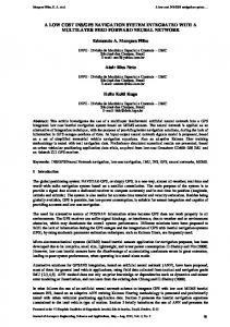
Figure 1 (left) : The spherical PROX mode was used to make a V-bar approach from 20 m down to 2 m where this image was taken showing Tango in orbit. Figure 2 (right) : Flight trajectory of the experiment executed on the 3rd of February 2011 using the virtual structure PROX mode. An image of Mango has been superimposed in correct scale right next to the B. In this article two experiments will be analyzed in detail, one for each PROX sub mode. First is a V-bar approach that starts 20 m ahead of Tango and takes Mango down to a closest distance of 2 m and then back out again. The experiment is an example of a frequent thrust scenario but where the thrusts are rather small, as the relative motion is following the V-bar. Figure 1 shows an image of Tango that was taken at the closest distance. The second experiment is a much more thrust heavy scenario where the objectives require a relative motion which is far from the natural orbit dynamics, see Fig. 2. In this experiment Mango is assumed to be a service satellite attached to a large space station. Mango is released from a waiting position (A) and has been given three objectives. First do an inspection of one of the solar panels, front side and back side (B). Secondly inspect the connection between the middle and front compartment (C). And finally pick up an object at (D) and return it to the front compartment (E). The scale of the space station with respect to Mango can be seen in the images as Mango is visible in correct scale close to (B). The space station is attached to tango which is located in the middle of the connection between the back and middle compartment. This scenario is using the virtual structure mode of PROX. These two flight experiments, that were executed on the 25th of January and 3rd of February 2011, will be used as examples when showing navigation and control performance as well as relative position trajectories.
2.
Navigation
There are also two separate navigation branches for PROX. One branch is based on GPS measurements and the same navigation function as used in the Autonomous Formation Flying (AFF) module[6]. The GPS Navigation has however in this experiment been tuned to work optimally with frequent thrusting. The other branch uses VBS measurements of the relative position and also the relative pose of Target. This paper will only focus on the GPS based proximity formation flying aspects, the VBS branch is out of the scope of this paper. The GPS navigation is based on a combined EKF processing of GRAPHIC (i.e., arithmetic average of pseudorange and carrier phase) and single difference carrier phase data types [7]. Compared to the other alternatives this concept suffers from a relatively high computational load and complexity, but guarantees good navigation accuracy, robustness to attitude uncertainty and different GPS antenna orientations, simplicity in filter initialization and maneuver handling. The selected filter estimation parameters comprise the 6-dimensional spacecraft state in the Earth Centered Inertial (ECI) frame, the scalar GPS receiver clock offset, a fixed number of force model parameters, including the aerodynamic drag coefficient and 3 empirical accelerations in the local orbital frame, and the 12 GRAPHIC float biases for each GPS receiver channel. Next to these 23 parameters, which are estimated for each of the co-orbiting spacecraft, we include 3 Mango orbit maneuver increments expressed again in the local orbital frame for a total filter size of 49 states. This approach gives the possibility to incorporate the orbit control maneuvers within the navigation process through their direct estimation, and to take into account deficiencies of the maneuver model via dedicated white or colored process noise. The GPS navigation filter was originally designed for a scenario with sparse thrusting, but with a dedicated tuning of the filter where the expected noise of the pseudorange, carrier phase and the GRAPHIC ambiguities was increased also scenarios with frequent thrusting could be estimated with high accuracy and reliability.
Figure 3 : Relative navigation error w.r.t. POD around the 2 m approach. Orbit control maneuvers are indicated as vertical red lines.
Figure 4 : Relative navigation error w.r.t. POD for the virtual space station inspection. Orbit control maneuvers are indicated as vertical red lines. The on-board navigation errors, Fig. 3 and Fig. 4, are computed through a comparison of the navigation state generated on-board by the GNC subsystem with the precise orbit determination (POD) products generated post-facto on-ground. As shown during the commissioning phase, the reference ephemerides can be used as a trustworthy reference since they are affected by errors 5 to 10 times smaller than the on-board absolute and relative navigation respectively [8]. Comparing Fig. 3 and Fig. 4 it is not surprising to see that the navigation performance is quite different between the two scenarios. For both experiments the active GPS antenna is pointed to zenith but the thruster activity is quite different. It is clear that the performance is reduced with increased thruster activity, this is in accordance with expectations. Thruster activity is summarized in Table 1. Table 1 : Thruster activity during different PROX experiments Scenario 2m approach Space station
Duration [Orbits] 0.9 2.4
Total delta-V [m/s] 0.123 0.965
Nr of thrusts 31 98
Table 2 : On-board GPS navigation errors during PROX and comparing with a typical sparse thrust scenario (about one thrust per orbit). mean±std Scenario Sparse thrust 2m approach Space station
Relative position [cm] R 0.03±5.2 -0.2±6.2 -5.4±12.9
T 0.38±5.0 -2.4±6.7 -2.1±16.6
N 0.01±3.3 14.3±3.0 -5.6±5.5
Relative velocity [mm/s] R 0.02±0.18 -0.14±0.58 -0.54±1.98
T -0.03±0.1 -0.03±0.48 0±0.67
N 0.00±0.09 -0.03±0.23 0.02±0.67
Table 2 summarizes navigation performance for different PROX experiments and also compares it to the normal navigation performance in a sparse thrust scenario like AFF where the natural orbit dynamics shapes the relative orbit. It shall be noted that the
minimum delta-V for the thruster system was about 0.4 mm/s at the time of these experiments, which is smaller than the navigation accuracy. 3.
Guidance
As described in the introduction PROX orbit guidance has two sub modes. The first mode was used to perform the V-bar approach to 2 m. A V-bar approach is one of the simplest forced motions that can be created in this mode. It has also been used to create close distance fly-arounds, as well as reaching and holding an arbitrary relative position. For example in one experiment Mango was asked to align the Moon, Tango and Mango, which required holding a position 15 m away from Tango with a large offset in both cross-track and radial direction. The guidance module takes a target position and a time to reach the position as input. It generates a collision free trajectory to reach the target position from the current relative position. A middle point is also available as an optional input.
Figure 5: Tango aligned with the Moon, Image taken 26th of October 2010 from a distance of 15 m.
The reference from the 2 m approach can be viewed in green in Fig. 5. A middle point was used at [0 10 0] m which was reached at 18:51, the goal point was set to [0 3 0.4] m. Three meter in along-track between the center of mass of the two S/C means that the closest distance between them is about 2 m. An offset in cross-track was used to get Tango in the field of view of the camera which is mounted on the outside of Mango.
Figure 5. 2 m approach position reference in green and achieved relative position (POD) in blue. Executed delta-Vs are plotted in red. Delta-Vs are shown in mm/s.
The second experiment presented in this article has instead a series of target points to be reached. The avoidance region is also much more complicated and especially is non-convex. To calculate the flight path between the points Mango is using a road map containing all allowed paths and which is spanning the complete structure of interest. To find the best path Mango is using an A* optimization routine to find the route from the current location to the next target point. The resulting trajectory for this experiment can be viewed in Figure 6. The different parts of the inspection tour have once again been marked with A-E, which corresponds to the same sections as marked in Fig. 2. The inspection tour requires maneuvers which takes Mango very far from the normal orbit dynamics. In part B going out and maintaining a relative position as far as 40 m above and 25 m outside the orbit plane. In part C the relative trajectory makes a circle around the V-bar with radius 4 m but without any motion in along-track. The full circle takes about 20 minutes which is 20 % of one orbit.
Figure 6. Inspection of a virtual space station, position reference in green and achieved relative position (POD) in blue. Executed delta-Vs are plotted in red. Delta-Vs are shown in mm/s. Tango is located at the origin. 4.
Control
The control function used in PROX is shared with the Autonomous Formation Flying module (AFF) also developed by SSC [9]. The controller is based on a Model Predictive Control framework and is using the familiar Yamanaka-Ankersen state transition matrix for relative dynamics [10]. As the relative dynamics used by the controller is valid for an arbitrary elliptical orbit the approach used is valid also for orbits much more eccentric than the PRISMA orbit. In AFF the controller is using a planning horizon of typically one orbit, for PROX this is reduced considerably to be able to handle the quickly changing reference. For the two experiments presented here the controller has been set to compute with a time between delta-Vs of 150s. Each control cycle the controller tries to
minimize the required amount of delta-V for the next six delta-Vs and still follow the position reference with in the specified control box. For the 2 m approach the control box was set to [0.3 0.3 0.2] m. As can be seen in Fig. 7 this is achieved both for the on-board navigation and the on-ground computed POD during the full scenario except for a short period around 19:22 – 19:25 in along-track. Due to the limited processor capabilities on-board the controller is only checking that the control box is not violated at possible thrust times, configured for once every 150 s. As can be seen in the figure the relative position is inside the control box during the delta-V before and after the violation. Comparing with Fig. 5 it is clear that the reference is changing from a quick recede to a hold at this time, the controller notices the hold in advance and decides to break a bit earlier than the reference to not over shoot. At this time the reference was going back with a bit more than 2 m per 150 s, it would be possible to reduce the control box violation by increasing the controller frequency. However the GPS navigation filter is only processing navigation measurements every 30 s, this means that it only acquires 5 measurements between controller cycles and possible delta-Vs with a control period of 150s. Reducing this period further would degrade the navigation, so the controller period setting is a trade off between navigation performance and controller responsiveness.
Figure 7. Control errors based on POD in blue and based on the on-board navigation in green. The control period was set to 150 s and the control box was set to [0.3 0.3 0.2] m. Location of orbit control maneuvers are indicated as vertical red lines. For the space station inspection tour the natural relative dynamics are affecting Mango much more as the distance away from the V-bar is much larger. The required delta-Vs to follow the quickly changing reference are also much larger, leading to reduced navigation performance. Because of this the control box was increased to [0.5 1 0.5] m, the control period was however kept at 150s. The control errors are shown in Figure 8, once again with the respective parts marked with the letters A to E. For along-track the relative position is kept with in the control box with margin during the full experiment for both the on-board and the on-ground calculated relative position. Cross-track shows some short violations during part B and C at the same time as the reference is changing quickly. This is the same effect as was seen in Fig. 7 during the 2
m approach, where the control box is violated between the times where the control box is checked by the controller.
Figure 8. Control errors based on POD in blue and based on the on-board navigation in green. The control period was set to 150 s and the control box was set to [0.5 1 0.5] m. Location of orbit control maneuvers are indicated as vertical red lines. The radial component also shows these effects for the fast reference of part C but also many times for part B where the controller has to struggle quite a lot against the natural orbit dynamics 40 m above Tango, requiring frequent delta-Vs in the range of 5-10 s of ontime. Here the control box is even violated with up to 0.2 m during a check of the control box. This is due to the reduced navigation performance. More specifically when checking the velocity navigation error, shown in Fig. 9, the navigation error is up to 3 mm/s during this period.
Figure 9 : On-board navigation error when compared to POD. Some outliers have been cut out to make it possible to zoom in on the general behavior. Radial has single outliers up to 19 mm/s, along-track and cross-track have outliers up to ±4 mm/s.
A 3 mm/s error gives over the control period of 150s a control error of about 0.45 m. The model predictive controller is using a robustness method to make it less sensitive to navigation errors by optimizing the trajectory for a relative velocity which is considered to have a noise of up to 1 mm/s. This fits well with the performance in along-track and cross-track, however for a scenario where there is very heavy thrusting in one direction the considered noise in this direction should have been increased, for this specific scenario to about 3 mm/s. However this was not discovered until after the PROX experiment slot was finished and has to this date not been possible to re-schedule the experiment to verify in orbit. Table 3 : Control statistics during the two PROX experiments presented in the article. mean±std Scenario 2m approach Space station
Relative position on-board [c m] R -7±15 -29±38
T -2±13 5±25
N -6±9 3±16
Relative position POD [c m] R -7±13 -34±43
T -4±14 3±35
N 8±9 -3±16
Table 3 summarizes control performance for the two different PROX experiments both using on-board navigation (input to the controller), and on-ground post processed navigation data. Conclusion The PROX GPS experiments goal is to show the feasibility and practical application of a GPS navigation system in closed loop with an autonomous forced motion control system in extreme proximity of another spacecraft. This article has presented in detail results from two very different proximity experiments, one involving low thrust activity, the other with very heavy thrusting. Even though the GPS navigation filter originally was not designed for frequent thrust scenarios, it is capable of handling the very quickly changing activities of Mango. The experiments have shown that the PRISMA PROX GPS concept is viable when two S/C are cooperating. However if a relative precision below a few dm is required, the GPS navigation would need to handover to a more precise navigation system at that stage.
References [1] S. Persson, B. Jakobsson, E. Gill, PRISMA Demonstration Mission for Advanced Rendezvous and Formation Flying Technologies and Sensors, 56th International Astronautical Congress, IAC-05-B5.6.B.07, Oct. 2005. [2] S. Persson, P. Bodin, E. Gill, J. Harr, J.L. Jørgensen, PRISMA – An Autonomous Formation Flying Mission, Proceedings of the 4S Symposium Small Satellites, Systems and Services, ESA SP-625, 2006. [3] S. Persson, S. Veldman, P. Bodin, PRISMA - A Formation Flying Project in Implementation Phase, Acta Astronautica, Vol. 65, Issues 9-10, 2009, pp 1360-1374. doi:10.1016/j.actaastro.2009.03.067 [4] P. Bodin, R. Larsson, F. Nilsson, C. Chasset, R. Noteborn, M. Nylund, PRISMA: An In-Orbit Test Bed for Guidance, Navigation, and Control Experiments, Journal of Spacecraft and Rockets, Vol. 46, No. 3, 2009, pp 615-623. doi:10.2514/1.40161 [5] P. Bodin, R. Noteborn, R. Larsson, C. Chasset, System Test Results from the GNC Experiments on the PRISMA In-Orbit Test Bed, Acta Astronautica, 2010, doi: 10.1016/j.actaastro.2010.08.021, To appear. [6] R. Larsson, R. Noteborn, P. Bodin, T. Karlsson, A. Carlsson, Autonomous Formation Flying in LEO, SFFMT2011, To appear [7] D’Amico, S., Ardaens, J.-S., Montenbruck, O, Navigation of Formation Flying Spacecraft using GPS: the PRISMA Technology Demonstration. ION-GNSS-2009, Savannah, USA. [8] Ardaens J.-S., D'Amico S., Montenbruck O., Final Commissioning of the PRISMA GPS Navigation System, 22nd International Symposium on Spaceflight Dynamics; 28 Feb. - 4 March 2011, Sao Jose dos Campos, Brazil. [9] R. Larsson, S. Berge, P. Bodin, U. Jönsson, Fuel Efficient Relative Orbit Control Strategies for Formation Flying Rendezvous within PRISMA, Advances in the Astronautical Sciences, Vol. 125, pp. 25-40, 2006; also AAS Paper 06-025, Feb. 2006. [10] Yamanaka K. and Ankersen F., New State Transition Matrix for Relative Motion on an Arbitrary Elliptical Orbit, Journal of Guidance, Control, and Dynamics, Vol. 25, No. 1, 2002, pp 60-66.