SIMULATION http://sim.sagepub.com
GroupSim: A Collaborative Environment for Discrete Event Simulation Software Development for the World Wide Web Wladimir Araújo Filho, Celso M. Hirata and Edgar T. Yano SIMULATION 2004; 80; 257 DOI: 10.1177/0037549704044882 The online version of this article can be found at: http://sim.sagepub.com/cgi/content/abstract/80/6/257
Published by: http://www.sagepublications.com
On behalf of:
Society for Modeling and Simulation International (SCS)
Additional services and information for SIMULATION can be found at: Email Alerts: http://sim.sagepub.com/cgi/alerts Subscriptions: http://sim.sagepub.com/subscriptions Reprints: http://www.sagepub.com/journalsReprints.nav Permissions: http://www.sagepub.com/journalsPermissions.nav
Downloaded from http://sim.sagepub.com at PENNSYLVANIA STATE UNIV on April 12, 2008 © 2004 Simulation Councils Inc.. All rights reserved. Not for commercial use or unauthorized distribution.
METHODOLOGY
GroupSim: A Collaborative Environment for Discrete Event Simulation Software Development for the World Wide Web Wladimir Araújo Filho Celso M. Hirata Edgar T. Yano Department of Computer Science Instituto Tecnológico de Aeronáutica CTA-ITA-IEC 12.228-900, S.J. Campos, SP, Brazil
[email protected] The simulation process involves the collaboration of different participants, such as simulation analysts, programmers, statisticians, and users of the simulation software. Many simulation tasks such as modeling, verification, validation, and design for experimentation require the participants to meet. It is understood that these meetings are time-consuming and expensive. This paper proposes a collaborative environment to help with the tasks of discrete event simulation software development using the World Wide Web platform. The environment, named GroupSim, is based on a collaborative computer system and uses the concepts of distributed modeling with automatic program generation and distributed control of experimentation. The authors show some examples to illustrate the use of the environment and discuss some issues related to collaborative environments such as concurrency control, access control, awareness, and performance. Keywords: Web-based simulation, collaborative simulation, simulation modeling, World Wide Web
1. Introduction The simulation process can be very complex and lengthy because it involves interactions among different participants, such as simulation analysts, programmers, statisticians, and users of the simulation software, for performing many different tasks. The participants are expected to interact to perform many different tasks, such as modeling, programming, verification, validation, and design for experimentation. It is common for the people involved in the process to be widely geographically distributed. For the successful execution of most tasks, the participants must meet for group work. Thus, much preparation and many meetings are necessary to effectively verify and validate the model and to plan, run, and analyze the experiments. Even after the program is built, many parameters are further tuned until the simulation study can be considered complete. It is understood that the costs associated with holding such meetings are considerable, both monetary and time wise. The use of a computational tool that allows each participant to cooperate in accomplishing each task,
SIMULATION, Vol. 80, Issue 6, June 2004 257-272 © 2004 The Society for Modeling and Simulation International DOI: 10.1177/0037549704044882
| | | | | |
independently of its geographical location, could reduce the number of meetings necessary for successful service completion, thus reducing its cost and the time of delivery. Any computerized tool to help with this process must take into account this context. Therefore, before we present our proposal, it is important to discuss how a collaborative computerized environment can be integrated in a simulation process to deliver the claimed benefits. We argue that certain tasks of the simulation process can be performed concurrently while others cannot. Furthermore, we argue that the modeling language of choice must be intuitive enough to allow an easy communication with the participants and formal enough to allow the automatic derivation of an executable program. The objective of the article is (1) to present a computerized collaborative environment that implements group work and (2) to analyze its usability and suitability in supporting the simulation process. The next section discusses how a collaborative computerized environment such as a groupware can help in the simulation process. Section 3 presents the related work. Section 4 describes the modeling language. The fifth section presents the GroupSim environment and its characteristics. The sixth section discusses some case studies, together with some strengths and weaknesses of GroupSim. In the last section, some conclusions are drawn, and future work is proposed.
Downloaded from http://sim.sagepub.com at PENNSYLVANIA STATE UNIV on April 12, 2008 © 2004 Simulation Councils Inc.. All rights reserved. Not for commercial use or unauthorized distribution.
Araújo Filho, Hirata, and Yano
2. Groupware and the Simulation Processes This section discusses how a collaborative environment such as a groupware can help in the simulation process. For this, we use the simulation life cycle proposed by Nance and Balci [1] and completed in Balci [2]. The simulation process can be divided into 10 tasks [1]: problem formulation, investigation of solution techniques, system investigation, model formulation, model representation, programming, design of experiments, experimentation, redefinition, and presentation of simulation results. The first 2 tasks deal with recognizing a problem and its representation to enable specific research action and selecting techniques to solve it. With respect to an environment, we assume that the outcome of these tasks is a description of the problem sufficient for the use of simulation as the technique of choice in solving it. During the system investigation, the system is decomposed into subsystems of manageable complexity, which are the input for the model formulation task. In this task, a conceptual model is built. This model only exists in the modeler’s mind. The translation of this conceptual model into a model that can be communicated to other participants is the task of model representation. The communicative model is then translated into a programmed model (i.e., an executable simulation model) in the programming task. The following tasks are the design of experiments, in which a satisfactory plan to gather the desired information is developed, and experimentation, when experiments with the model are conducted with a specific purpose. The simulation results, the product of the experimentation task, may indicate a need to update the model or its representation for a number of reasons [1]. Once the simulation results are acceptable from the analysts’ point of view, they are interpreted and presented to the decision makers for their final acceptance and implementation. The tasks that precede the model formulation and the ones that succeed the experimentation are outside the scope of our discussion. Thus, our discussion addresses part of the simulation process. It starts with the product of the system identification task and ends with the simulation results. In a computerized environment, it is important to note that two or more tasks can be seen as a single one. For instance, because the product of model formulation is an abstraction, we can assume that both tasks—model formulation and model representation—are being performed iteratively during the construction of the communicative model. We refer to this combined task as the modeling task. However, it is important to note that there might be differences in terms of participants’ responsibility in this specification. One participant may be responsible for model formulation, while another would be responsible for model representation. Balci [2] also defines 13 credibility assessment stages (CASs) for the simulation tasks. The purpose of these stages is to assess the acceptability and credibility of the simulation results. Balci points out that assessing the accu-
racy (i.e., validation and verification) is a task that must be performed upon the completion of each simulation phase. The outcome of these stages is an update of one or more products of the 10 simulation tasks defined above. We only consider those stages that are related to the tasks of modeling, programming, design of experiments, and experimentation. Assessments are candidate operations to be performed in a collaborative computerized environment. It is also possible to combine two credibility assessment stages as we do for the tasks. For instance, similar to the combination of model formulation and model representation, we can also consider their credibility assessment stages—namely, model qualification and communicative model validation and verification—as a single stage. We refer to this stage as the modeling assessment stage. It is important to observe that these simplifications occur naturally when using a computerized environment. In the programmed model verification stage, the programmed model (software) is verified against the communicative model, as well as the system and objectives definition. Many techniques can be used. Specifically, with respect to a computerized environment, we believe that animations and traces of message passing can be very useful. The experiment design verification deals with the correct inputs, initial state, and analysis techniques employed in the simulation experiments. In the data validation stage, it is confirmed that “the data used throughout the model development phases are accurate, complete, unbiased and appropriate” [2]. The model validation CAS checks if the experimental model behaves consistently with the study objectives. This is made by comparing the behavior of the system and the model under identical input conditions. All these tasks and CASs involve the collaboration of different participants with different expertise. For the modeling task and the model verification, participants must understand the system being modeled. These participants may be clients of a consulting service in a simulation. From the consulting side, the simulation analyst helps with the modeling by collecting information for model construction and by conveying the specification for the programming task. The simplicity and accuracy of the communicative model play an important role in the communication among simulation analysts, clients, and programmers. A model can be represented in many forms: icons that mimic the entities of the system in a computer screen, Petri nets [3], informal diagrams, and activity cycle diagrams (ACDs) [4]. A formal representation language, such as DEVS [5], can also be used. The drawback of employing such a language is that it requires investing time to learn its semantics and syntax, which might not be a problem for the analysts or the programmers but probably is for the clients. Nowadays, it is common for model specifications to be automatically translated into programs, facilitating the work of the simulation analyst. This is possible if the specification language is well defined and nonambiguous. Simulation experiments can then be performed and their results made readily available to the collaborators, who can
258 SIMULATION Volume 80, Number 6
Downloaded from http://sim.sagepub.com at PENNSYLVANIA STATE UNIV on April 12, 2008 © 2004 Simulation Councils Inc.. All rights reserved. Not for commercial use or unauthorized distribution.
GroupSim
validate the model or change it to better reflect the system. The advantage of this approach is that the produced model can be quickly refined, saving time and money by expediting the validation task and facilitating the verification. The main drawback is that the specification language imposes some restrictions on which models can be constructed. When the program is ready, the plan of experiments and the experimentation are performed. For this task, some knowledge of statistics is necessary for the plan to be efficient. For the simulation of large and/or complex systems, this process may consume much of the participants’ time. We believe that modeling is a task that requires the participants to interact most. The analysts have to translate the concepts obtained from the system experts to a model. They need to interact several times for this to happen, mostly because the informal descriptions provided by the specialists will not be as complete as the analysts would like them to be. They might even contain ambiguities and contradictory statements. These problems are mostly solved during the model construction. However, a lot of time is spent building a model to its end. A tool that allows the participants to synchronously cooperate in model construction can reduce the development time because most of the inconsistencies can be detected at the moment they appear. This is true if both the analysts and the field experts use a common language for model representation. Ideally, this language has to be formal enough to describe the model with no ambiguities and simple enough for the experts to understand without having to resort to expensive or lengthy training. During the modeling, the help of a statistician might be interesting when deciding how to perform a measurement. It could be the case that a model has to be altered to perform certain measurements, and again, time can be saved if these changes can be communicated during the model building. The model is reviewed by analysts, field experts, statisticians, and programmers as part of the data validation and model validation CASs. These reviews usually take the form of a meeting in a room with the presence of the collaborators. These review meetings cannot be eliminated but can be reduced if the development of the model takes place in an environment that constantly provides the illusion of such meetings. Thus, for a tool to be effective, it needs to support distributed modeling and must include some mechanisms for participation management so that it creates an illusion of a meeting in a room with the presence of the collaborators. Regarding the programming task, the need for interaction is generally lower. Programmers will take the model specification as input and produce the simulation program. In general, both programmers and analysts possess more knowledge about the tools deployed for the programming task, and the interactions between them are more straightforward. The validation of the program requires the participation of the whole group. In general, the group validates the program using a black box approach (i.e., they compare the output of the program with the expected behavior of the system). It is assumed that analysts (software
testers) perform the tests of the program’s code (white box validation). For the design of the experiment task and the related experiment design verification stage, which may implicate changes that need to be made to the programmed model, some interaction between the programmers, analysts, and statisticians is necessary. The interaction increases when the experimental model has to be validated to include the clients. Distributed platforms, such as the Internet, have been employed to help users to perform the tasks of the simulation process. Perhaps it is useful to discuss how distributed platforms are helping the simulation tasks. One can think of a distributed platform to help modeling by allowing people to interact either synchronously or asynchronously. The computer-supported cooperative work (CSCW) area addresses this. CSCW studies and tries to understand how people work together (both with and without groupware) and how the computer and related technologies can be designed to support effective collaborations. According to Ellis, Gibbs, and Rein [6], groupware includes computer-based systems that support groups of people engaged in a task or common objective and provides an interface for a collaborative environment. Groupware systems can be classified according to two criteria: geographic location of the users and the supported interaction type. The first criterion distinguishes between local, in which case the users interact personally, and remote, in which case the interaction is performed through a computational system. The second criterion distinguishes between synchronous, in which case there is the notion of simultaneity, and asynchronous, in which case there is not such a notion. In a synchronous system, events generated by a user are immediately delivered to the other participants. Another important concept used in groupware is awareness. This is roughly a feeling of illusion through which one can sense the presence of the participants and their movements by sharing a workspace. Greenberg [7] describes awareness as a list of information elements that participants may keep track of when they work with others in a shared space. The information elements include identity (who is participating in the activity?), location (where are they?), activity level (are they active in the workspace?), action (what are they doing?), intentions (what are they going to do?), changes (what changes are they making?), objects (what objects are they using?), extents (what can they see?), abilities (what can they do?), sphere of influence (where can they have effects?), and expectations (what do they need me to do next?). As can be inferred, it is difficult to provide adequate awareness for groupware systems. As an example, one technique to achieve some awareness is the use of multiuser pointers, or telepointers. Every user owns a telepointer, and all collaborators can observe its movement. A session in groupware terminology is “a collaborative activity in progress” [8]. A session is composed of a group of collaborators sharing objects and messages. To
Volume 80, Number 6
Downloaded from http://sim.sagepub.com at PENNSYLVANIA STATE UNIV on April 12, 2008 © 2004 Simulation Councils Inc.. All rights reserved. Not for commercial use or unauthorized distribution.
SIMULATION 259
Araújo Filho, Hirata, and Yano
coordinate the activities of the group of users, a session manager, who controls the group’s access to the objects, must define the properties of the session and control the entrance and exiting of users to and from the session. Combining simulation process and groupware leads to the discussion of some concepts. In what we name distributed modeling, the participants of the simulation process interact among themselves with the help of groupware. The model is built and updated using the groupware. We make an important distinction between distributed control of experimentation and experimentation using distributed platforms, also known as control of distributed experimentation. Distributed control of experimentation allows for the control and monitoring of a particular experiment being executed on a specific host by different collaborators, which interact with the experimenting system by using a distributed platform. On the other hand, control of distributed experimentation is concerned with controlling the execution of a concurrent simulation program in several machines, generally aiming at performance gains, as in parallel discrete event simulation (PDES), or at interactivity with the user, as in distributed interactive simulation (DIS). Another aspect of distribution is related to the programming task. One can envision a CSCW process of several programmers cooperating to build (or writing the code of) a simulation program. If an automated approach is used for programming, one can think of a CSCW process of several analysts collaborating to specify a model that will be automatically translated into a program. We call this approach distributed modeling with automatic programming. The current communication infrastructure provided by the Internet and the World Wide Web (WWW) allows computers placed anywhere to exchange information using the TCP/IP protocol, thus making some techniques such as CSCW more accessible to Internet users. The World Wide Web uses the client-server architecture with a standard interface—the Web browser—which provides easy and safe access to the system. Even with all the facilities provided by the Internet, the development of software capable of operating in a uniform manner in many existing hardware and software platforms is a considerable engineering effort, and it generally leads to high costs. The Java programming language [9] is one of the main tools that addresses this issue. Java code is portable and executes on almost any machine and any operating system. The reason for this is that Java uses the concept of the virtual machine, which guarantees platform independence to any compliant program. By joining the Internet and Java technology with the concepts of groupware and distributed programming, it is possible to create a simulation environment capable of allowing the creation of a simulation model, its coding, and experimentation in a collaborative form. During the panel Research and Commercial Opportunities in Web-Based Simulation of the 2000 International Conference on Web-
Based Modeling & Simulation, some researchers found that such an environment is of great help in the simulation process. We share this belief. The solution we propose, named GroupSim, is a synchronous groupware environment that helps the modeling, programming, and experimentation tasks of the simulation process in the WWW. GroupSim uses the concepts of distributed modeling with automatic programming and distributed control of experimentation. We allow automatic simulation program generation to simplify design and enhance portability.
3. Related Work The related work is still scarce. Sarjoughian and Zeigler [10] propose DEVSJAVA, an environment based on the DEVS formalism that facilitates model development and simulation independent of hardware by using a Javaenabled browser. They also indicate that the environment can provide the foundation to enable collaborative modeling and experimentation; however, no implementation of collaborative modeling is presented. Seibt, Schumann, and Beikirch [11] propose a Webbased simulation architecture supported by HTML pages combined with computer-generated image (CGI) scripts, Java applets, Java programs, and other platform-dependent tools. Although their proposal provides powerful resources, the modeling is not intuitive, and the tool is not completely portable due to its use of some platformdependent systems. Besides, the use of Java applets with CGI scripts presents worse performance compared to a pure Java solution [12]. Since the modeling task is based on HTML forms, it is not a synchronous activity. Lorenz et al. [13] present many client-server interaction strategies, including the one we adopt for GroupSim. Nevertheless, synchronous modeling is not addressed. Some simulation language proposals based on Java can be found in Healy and Kilgore [14] and Kreutzer, Hopkins, and Mierlo [15]. The former presents a class library and encapsulates it in Java Beans [12] components, allowing the visual creation of programs by the interconnection of these components. All the presented proposals are based on the generation of an intermediate code in some general-purpose objectoriented language, such as Java [14, 15] or C++ [16], or a simulation-specific language, such as javaGPSS [11], and its further compilation. GroupSim is based on the runtime interconnection and configuration of objects to directly produce a simulation program without the use of a compiler. Page, Moose, and Griffin [17] propose an extension to SimJava by using the remote method invocation via Java RMI. Those modifications, though, do not allow collaborative modeling, only the distributed execution of the simulation program.
260 SIMULATION Volume 80, Number 6
Downloaded from http://sim.sagepub.com at PENNSYLVANIA STATE UNIV on April 12, 2008 © 2004 Simulation Councils Inc.. All rights reserved. Not for commercial use or unauthorized distribution.
GroupSim
Fujimoto and Perumalla [18] describe Jane, in which Java clients control simulations running on multiple servers. Despite the portability achieved with the use of Java, the impossibility of using the applets, which would allow the use of a Web browser, forces users to install the client software in their machines. Furthermore, no provision for user control is present. Another detail is that it also makes use of an intermediate code to generate the simulation program. Pidd and Cassel [19] describe JUST, a client-server system for executing simulations written in Java. JUST provides a framework in Java to build simulations according to a three-phase worldview. Although distributed, JUST is not collaborative since each client interacts only with the server, the simulation executive. Also, despite being made totally in Java, the simulation is not interpreted; it needs to be compiled into Java classes. In a different approach, Taylor [20] describes the use of Microsoft’s NetMeeting tool as a facilitator for distributed modeling. NetMeeting is a powerful tool that allows remote application sharing and provides aggregated communication tools (chat, voice, and video) for the meeting participants. Taylor concludes that its main feature is application sharing, which allows the participants to synchronously build a simulation model irrespective of the modeling tool. Its use as a groupware tool for distributed modeling possesses, however, various drawbacks. Concurrency control is very primitive. Once a participant requests control of the application being shared, he or she has to explicitly grant control to another who wants to modify the model, which would severely affect usability. GroupSim allows more concurrency with the model edition, using a simple and transparent lock mechanism. From the usability point of view, all NetMeeting participants must work with the same application at the same time since they share the application. This might not be an issue for only two people cooperating, but it becomes a concern when the number of participants grows. Finally, NetMeeting is limited to the Microsoft platform. An apparent advantage of NetMeeting is the aggregate services. Since GroupSim is one of many GroupPlaces [8] applications, it can easily be augmented with tools for chat, voice, and video communication. A short description of GroupPlaces is presented in section 4.2. The above discussion is applicable not only to NetMeeting but also to any other tool that was not designed to support the simulation process. Lima and Hirata [21] propose GroupGraph, which is a collaborative tool to aid modelers in representing the model. It is a groupware system and allows configuration of the editor as well as representation of hierarchical graphs. Some model specifications that can be promptly used include Petri nets and activity cycle diagrams (ACDs). Their groupware differs from GroupSim in some aspects: GroupGraph neither generates code nor runs the code, but it does allow for the hierarchical representation of ACDs. Gil and Hirata [22] propose XACDML. XACDML is
an XML (Extensible Markup Language) based on ACDs that is designed to allow the easy exchange of simulation model information on the Internet. With XACDML, simulation software environments are able to interoperate and provide a more integrated approach for simulation processes. XACDML is currently being added to GroupSim. More recent research on Web-based simulation can be grouped into two classes: studies based on the (1) application server provider (ASP) and (2) the Web service. An ASP installs, configures, and maintains enterprise-class software on its own server and allows its users to access the software remotely, which is normally over a secure Internet connection using an Internet browser. Web services can be defined as “loosely coupled, reusable software components that semantically encapsulate discrete functionality and are distributed and programmatically accessible over standard Internet protocols” [23]. A primary goal of Web services is interoperability. ASPs differ from Web services because ASPs deliver entire applications from a central hosting location, while Web services are distributed components. ASPs form a closed solution for functionality, while Web services are inherently extensible. Marr et al. [24] present an ASP technology to run simulation experiments. The server takes and manages requests for simulation executions from Web clients. Typically, a client sends a request to run an experiment to the server. The server creates jobs from the client request and sends new requests to other servers taking part in a group named alliance. The alliance processes the requests and sends the results back to the ASP server, which compiles all results and delivers them to the client. Henriksen et al. [25] propose the Web-based simulation center (WBSC), which is a framework for tools supporting Web-based simulation in general and cooperative work on simulation projects in particular. The framework uses ASP as the underlying technology. It implements user and project management to support cooperative project work, handles authorizations for accessing integrated software tools, and includes a communication tool and a file manager to support communication and cooperation. It also provides for simulation and animation, currently with GPSS/H and Proof Animation, to Web- enabled formats. As an ASP-based solution, however, WBSC does not provide for synchronized cooperative modeling. Kilgore [26] shows how Web services with .NET technology can be used in a simulation. He shows the creation of Web services in simulation model development using VS.Net. The Web service was created to access static information during the execution of the simulation. He points out that Web services also bring performance penalties, security considerations, and availability risks in a distributed implementation. Chandrasekaran et al. [27] discuss how Web services can be used in the simulation process. Basically, they discuss three alternatives: whole models as Web services,
Volume 80, Number 6
Downloaded from http://sim.sagepub.com at PENNSYLVANIA STATE UNIV on April 12, 2008 © 2004 Simulation Councils Inc.. All rights reserved. Not for commercial use or unauthorized distribution.
SIMULATION 261
Araújo Filho, Hirata, and Yano
environmental components as Web services, and model federates as Web services. In the first alternative, complete simulation models are made available as Web services. For instance, a traffic system as a network of highways could offer services of traffic simulation to predict the traffic condition under certain scenarios. In the second alternative, the simulation process uses Web services as a means to obtain and store data and produce animation of the simulation program. As an example, a simulation experiment could obtain input data using Web services from a database. In the third alternative, model federates would be coded as Web services. In this approach, the trade-off between the Web service overhead and the interoperability benefits should be taken into consideration. GroupSim differs in the same way that ASPs differ from Web services. GroupSim is not extensible either. GroupSim could be thought as an ASP application. However, GroupSim is a tightly coupled client-server solution, whereas ASP applications, in general, have a loose coupling based on the HTTP protocol. This results in better performance and poorer flexibility for the integration for GroupSim. 4. The Modeling Language The ACD [4] is a well-known and widely used notation to model discrete event simulation systems in the United Kingdom. It very much resembles timed Petri nets [3], and it describes the behavior of each entity in the system as a cycle, from its creation to its death. Every cycle is composed of two kinds of states: active and dead. Active and dead states are connected by directed arcs, which indicate the path the entity should follow. In the dead states, the entities wait to be served by a subsequent active state. Once the conditions to an entity to be served are met, it is removed from the dead state and placed in an active state. At this moment, it is already known when the entity will leave the state and proceed to the next state to wait for another service. After the completion of the cycle, the entity leaves the system. With this basic scheme, several kinds of systems can be described in a general behavioral way, but to fully define a whole system with its intricacies, we need more information. We briefly describe here the extended notation we adopt so the examples can be understood. Its full description can be found in Araujo Filho [28]. As with regular ACDs, dead states are represented by circles and active states by rectangles. The first modification is the elimination of the entity cycles. This elimination is accomplished with the creation of two specialized active states: generate and destroy. Generate is where the entities are created and inserted into the system. Destroy is its counterpart: the place where they leave the systems and are destroyed. Both systems are proved equivalent in Hirata and Paul [29]. This alteration does not improve the power of representation but is “intended to improve the communication between users and simulation analysts” [29]. The
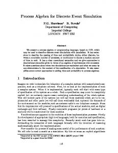
generate and destroy active states are called external active states since they interface with the outside. The others are called internal active states. The common (internal) active state is also called activity. Dead states are places where the entities wait until they are allowed to proceed to active states. Entities can be temporary or permanent entities. Temporary entities (like customers in a bookstore) are generated and destroyed. Permanent entities can be thought of as resources (like baskets in a laundry room) that servers use to provide the service to the temporary entities. Dead states that hold permanent entities (called resource queues from now on) are identified by an “R” placed in the circle. Since the dead states that contain temporary entities normally behave like a queue, they will be referred to simply as queues. Queue disciplines are not represented graphically. One addition to the notation is the use of conditional arcs connecting queues to activities and vice versa. Figure 1 shows the use of conditional arcs. All dead states are queues; the resource queues are not shown. Although the syntax is the same for incoming and outgoing conditional arcs, their semantics are completely different. For an activity to begin service, it is a precondition that all input queues (queues that have arcs pointing to the activity) have an available entity. It is also necessary that each connected resource queue has, at least, the amount of resources required by the activity. This number may differ for each resource queue. With conditional arcs, which connect an input queue to an activity, it is also necessary that the stated condition evaluates TRUE to that entity. If such condition evaluates FALSE, the entity will not be allowed to proceed to the activity, preventing the activity to begin service. That is, in Figure 1a, for activity A1 to begin service, there must be at least one entity in queues q1 , q2 , and q3 ; for the entity in front of q1 , C1 evaluates TRUE, and for the entity in front of q2 , C2 evaluates TRUE. For the arc connecting q3 to A1, it is assumed that a constant condition evaluates TRUE, regardless of the entity in front of q3 . Conditional arcs are not allowed to connect to resource queues. The conditions in conditional arcs are Boolean and logical expressions, with operands referencing entity attributes, queue attributes, and state variables. Entity attributes refer to attributes of the entity at the head of the queue. Once the preconditions are met, one entity from each queue enters the activity, the resources are acquired, and the service begins. After the completion of the service, entities are sent to the specified queues, and the resources are also released and sent to the related resource queues. It should be noted that if a queue is full (for the ones with limited capacity), an incoming entity is not accepted. The destiny of such an entity will depend on the kind of source-active state. If it is coming from a generate state, it will leave the system as if it were destroyed by a destroy state. Otherwise, the active state blocks the entity, thus
262 SIMULATION Volume 80, Number 6
Downloaded from http://sim.sagepub.com at PENNSYLVANIA STATE UNIV on April 12, 2008 © 2004 Simulation Councils Inc.. All rights reserved. Not for commercial use or unauthorized distribution.
GroupSim
q4
q5
q6
q3 C1
A1 C1
q1
q4 C2
q5 C3
A2
C2
q2
q3
q1
(a)
q2 (b)
Figure 1. The use of conditional arcs in activities and routers
preventing further service from starting, even if the preconditions are met. When the output queue has room for the entities, the active state unblocks and frees the entities and resources, resuming its normal operation. A blocked activity retains all entities and resources that are part of the service, even if it is due to only one full outgoing queue. A router (described next), on the contrary, retains all the entities it could not dispatch together with all the resources, which will be freed as soon as all the entities are sent. Output conditional arcs are present only in a special active state, called the router. The router is the combination of two kinds of components: the multiplex (MUX) and the demultiplex (DEMUX). A MUX is an active state that has many input queues but only one output queue. A DEMUX is an active state that has only one input queue and many output queues. A MUX gathers entities from many sources and sends them to a single destination. A DEMUX is its counterpart. It is responsible for separating entities according to its attributes. Like the MUX, which simply groups the entities independent of its nature, the DEMUX needs a criterion to distinguish them. The output conditional arcs provide such criteria. The precondition for a router to begin service is the same as that for the activity. After the service is complete, the resources follow their path, but the entities are directed to a queue according to the conditions stated on the output arcs. For each outgoing entity, there must be one, and only one, condition evaluating TRUE. In the example illustrated in Figure 1b, once the entities e1 and e2 (respectively, from q1 and q2 ) are served, each one is checked against conditions C1 , C2 , and C3 . If, for example, C2 evaluates TRUE for e1 , it is sent to q4 , and if C1 evaluates TRUE to e2 , it is sent to q3 . A router is represented by a rectangle with an “R” inside.
Another extension imported from the activity diagram for object-oriented programming (ADOO) [29] is the (here denominated) interrupt activity. An interrupt activity is an extended activity with the capability of being interrupted by another interrupt activity. If an interruption succeeds, the resources and entities under service are released back to their respective incoming queues. The symbol for the interrupt activity is the same as for the activity—a rectangle—but incoming or outgoing interrupt channels are represented by dashed arcs. An interrupt activity may interrupt as many activities as necessary and can be interrupted by any number of activities. An example is presented later as a case study in which an interrupt activity is used to model an emergency room. 5. The GroupSim Environment 5.1 Overview GroupSim uses the GroupPlaces [8] groupware architecture, which grants it two important characteristics of a Web application—namely, (1) client platform independence due to its Java-based implementation, which allows it to be executed on any Java-enabled Web browser, without any extension, and (2) ease of deployment due to the dynamic code-loading features of Java. GroupSim uses an extended version of the ACD as the specification language, mainly due to its conceptual simplicity, which permits simulation analysts to communicate with the clients [30]. Through its collaborative graphic editor, the collaborators can interactively produce a simulation model by interconnecting and configuring the several ACD building blocks. The ACD extensions we propose allow for the automated simulation generation from the graphic specification
Volume 80, Number 6
Downloaded from http://sim.sagepub.com at PENNSYLVANIA STATE UNIV on April 12, 2008 © 2004 Simulation Councils Inc.. All rights reserved. Not for commercial use or unauthorized distribution.
SIMULATION 263
Araújo Filho, Hirata, and Yano
developed using the collaborative graphic editor. This takes the programming task out of the loop. To accomplish this, we construct a mapping from the extended ACD notation to Java classes, which compose the simulation program through the proper interconnection of their instances. Through the collaborative environment, any collaborator can control the experimentation task. Once one starts the simulation execution, any other collaborator can stop, pause, or resume its execution. Once the simulation has ended, a report containing all the relevant information, as specified during the modeling task, can be easily generated. By its analysis, the model can be updated until it is finally an adequate representation of the system under study. Further experiments can then be made, and the obtained output data can be used to attain the simulation objective. 5.2 GroupPlaces Overview GroupPlaces is a groupware architecture for the WWW proposed by Yano [8]. GroupSim is a prototype implementation of GroupPlaces, which grants it very important characteristics. The environment uses Java-enabled browsers, such as Netscape, Internet Explorer, and HotJava. The idea is to explore a well-known and widely used platform so that no changes are required on the client side, which could otherwise restrict their use of groupware. GroupSim uses the metaphor of rooms [31]. Rooms are meeting points and recipients of shared objects. Each room identifies a model and can have users connected to it. It can also contain shared objects or artifacts, which in GroupSim are the graph model, model documentation, and input and output data. These shared objects are created, updated, and removed by users. GroupSim follows the client-server architecture, which imposes some drawbacks, such as lack of scalability; however, it simplifies the software development, allowing an easier and more reliable implementation. It is important to note that the client performs the graphic interface processing, which is significant, while the server accomplishes the management processing. GroupSim inherits the control mechanisms natively built into GroupPlaces: access control ensures that users have the proper authorization to enter a room (i.e., work on a model), concurrency control manages model sharing through the use of locks, synchronous awareness guarantees that changes in the model are immediately notified to users, and configuration control sets the bounds for a room, such as number of users and number of artifacts. The environment allows flexible construction of models through the presentation objects (windows). The server contains, besides the artifacts, the presentation objects. These objects act as a front-end or an interface for the artifacts. It is possible to have one-to-many or many-toone relationships between them. The presentation objects are dynamically loaded from the servers. This allows the client to load and configure the required objects on the fly.
5.3 The Collaborative Simulation Graphic Editor The collaborative editor is an artifact-presentation object pair, according to the GroupPlaces architecture. The artifact contains the information shared by the clients. For GroupSim, the shared information consists of the model representation using ACDs. The presentation object is the graphic interface that presents as an ACD to the collaborators and allows its editing through the interconnection of objects and their configuration through dialog boxes. The shared model is composed of two kinds of data: (1) the graphic data, which are necessary to represent the graphic ACD, and (2) the configuration data, which comprise all the information that describes the simulation model, which is used to automatically generate the simulation program. The graphic data are replicated in every client, but the configuration data are located only in the model server. This separation approach presents two advantages compared to the shared approach: (1) it reduces the data exchange between the server and the clients, thus improving the communication performance, since the configuration data are not broadcast to the clients, and (2) it isolates the user interface implementation from the model management, simplifying the management of the whole system. The separation approach is implemented by organizing the system in three layers. The presentation layer takes care of the graphic presentation of the model. The management layer stores the model configuration information (active and dead states, their configuration properties, and the arcs connecting them). The simulation layer is the executable simulation program. The presentation layer is replicated on every client, while the other two only exist in the server. The presentation object is a graphic editor capable of connecting artifacts to the model server, sending the updates performed by the user and receiving the model update notifications that originated with the other clients. Figure 2 shows the graphic editor displaying the model of the “harassed booking clerk” [4]. On the left-hand side of the window, two sets of buttons are presented: the upper ones select the next visual object to be placed in the design area on the center; the lower ones perform an action on the selected visual object, control the activation of the telepointers, and display the dialog box responsible for editing the model global variables. The simulation control buttons are located at the top of the window. They control the model generation and persistence, the simulation execution, and the report generation. The concurrency control mechanism we adopt is of a single model lock, which grants access to the model server to only one client at a time. This approach simplifies the implementation and compromises neither the performance nor the usability of the editor [28] since the lock is held for the usually short period of time necessary for a client to perform an operation. For example, adding a queue to the model consists of two clicks of the mouse. The first click is on the “Queue” button, which acquires the lock, and the
264 SIMULATION Volume 80, Number 6
Downloaded from http://sim.sagepub.com at PENNSYLVANIA STATE UNIV on April 12, 2008 © 2004 Simulation Councils Inc.. All rights reserved. Not for commercial use or unauthorized distribution.
GroupSim
Figure 2. Window of the collaborative graphic editor containing the activity cycle diagram (ACD) for the “harassed booking clerk” case
second click is on the model editor workspace to place the queue and release the lock. Configuration properties of the active states specify the probabilistic distribution at which the entities arrive into the system (generate) or of the service time (internal active states). Queues can have their discipline configured, and resource queues specify the initial number of resources they contain. All states can have multiple observers configured. An observer interacts with the entities that pass through a state by performing measurements (entity variables, delays, queue time, queue length) or changing them (time stamping, variable assignments). The output of a measurement can be simply a statistical summary or a histogram in a tabular format. The histograms can be fed into a graph
software package to produce a graphical representation. Such an output is present in the simulation report. Figure 3 shows the dialog boxes of some of the states of the “harassed booking clerk” example. Figure 3a shows that the resource queue is named clerk, and it contains one permanent entity initially. Figure 3b shows the properties of the queue for call entities. The first in, first out (FIFO) policy and an unlimited capacity are assigned to the queue. It is also configured to observe its length and the time that entities spend on it. Figure 3c shows the properties of the observer for the queue time. It is configured to generate a frequency histogram. The results will be part of the simulation results. Figure 3d shows the generate state of call entities. Such entities arrive with a Poisson distribution, with
Volume 80, Number 6
Downloaded from http://sim.sagepub.com at PENNSYLVANIA STATE UNIV on April 12, 2008 © 2004 Simulation Councils Inc.. All rights reserved. Not for commercial use or unauthorized distribution.
SIMULATION 265
Araújo Filho, Hirata, and Yano
Figure 3. Dialogs showing properties for different states of the “harassed booking clerk” case: (a) the resource queue containing the clerk; (b) the queue that holds call entities; (c) one of the observers of the “calls” queue, which measures the call waiting time; (d) the generate state, which introduces call entities into the system; and (e) the activity, which serves the calls.
an average of 5. Figure 3e shows the activity of serving a call, in which the service follows a normal distribution. The model server performs other functions besides model management. It also controls the simulation program generation and execution and the simulation report generation. All those functions are available to every collaborator through the model editor, and access to them is subject to the same concurrency control mechanism of the editing functions. The simulation program generation function interprets the configuration data (management layer) producing a network of interconnected objects that compose the simulation program (simulation layer). After its creation, the simulation program is ready to execute, which is controlled by the model server in response to the appropriate request from a collaborator. The simulation program execution oc-
curs in its own thread, freeing the model server to perform its functions. The simulation layer lasts until the end of the simulation execution, which is characterized by the completion of the simulation time or the termination of the processing of simulation events. The simulation can be accompanied by following the simulation log window, which is displayed once the simulation is started. The log contains all the information about the flow of entities so that all collaborators have the same view at the same time (synchronized view) of the output of the simulation run. The visual interactive simulation is not supported yet, although it could be included. In the next section, we discuss the simulation process that GroupSim induces by walking through an example— namely, the “harassed booking clerk.”
266 SIMULATION Volume 80, Number 6
Downloaded from http://sim.sagepub.com at PENNSYLVANIA STATE UNIV on April 12, 2008 © 2004 Simulation Councils Inc.. All rights reserved. Not for commercial use or unauthorized distribution.
GroupSim
Table 1. List of which tasks and CASs of the simulation process should be performed in a distributed or centralized form Task or CAS Modeling Programming Design of experiments Experimentation Model verification Programmed model verification Experiment design verification Data validation Model validation
Distributed
Centralized
X
should be noted that the cycles were opened and replaced by generate-destroy pairs. A typical sequence of operations to create the model and perform an experiment is as follows:
X X X X X X X X
5.4 The GroupSim Simulation Process GroupSim, due to its modeling language and automatic program generation capability, induces a particular process. This process reflects our ideas about which tasks and CASs are really necessary to be distributed and how it should be done. Looking at Table 1, we see that only the modeling and the experimentation tasks are distributed since the model server, without any user participation, performs the programming task automatically. The modeling task is performed not only concurrently but also synchronously to allow all collaborators to be aware of every change made before anyone else performs its own. This simple scheme, allied to the use of model locking, eliminates the occurrence of inconsistencies among the model copies of the users and the copy of the server. This greatly simplifies the software and does not have too much of an impact on the performance. The design of the experiments and its verification could be distributed, although the collaborative graphic editor does not support them yet. Multiple versions of the model containing the different settings can be created and saved on different files. The inconvenience is when the model is modified as a result of the data validation or model validation CASs, in which case each experiment would have to be updated. At least theoretically, these are activities to be performed in a distributed manner since they involve the collaboration of many participants with different expertise. The control of experimentation is also a distributed activity, although its execution is not (i.e., it follows the distributed control of the experimentation approach). The simulation runs in the server, but its progress can be controlled by any collaborator. In this context, we examine the construction of a simulation program for the “harassed booking clerk” case presented by Pidd [4]. It is simply a clerk that services customers in person or by phone. Both customers and phone calls arrive with given distributions. They both compete for the same resource: the clerk. After the service, the customers and the calls leave the system. The ACD of the system is presented in Figure 4. The resulting model is presented in Figure 2, which presents an extract from the collaborative graphic editor. It
1. Create the generate, activity, and queue objects. In the background, those objects are created in the model server and broadcast to the other collaborators. In the management layer, their corresponding objects are created. 2. Connect, for instance, the generate object to its output queue. In the background, an arc object is created in the server and broadcast to the other collaborators. In the management layer, the generate object is configured to point to the object associated with the queue. 3. Configure the objects via dialog boxes. In the background, the configuration data come from the server and then are altered and returned to it. 4. Steps 1 to 3 are repeated until the entire model is created and configured. 5. Generate the simulation model. In the background, the model server commands the task, which is controlled by the management layer. The simulation layer is created. 6. Execute the simulation. The model server commands the management layer to start the simulation. It then starts the scheduler in the simulation layer. 7. After the end of the simulation execution, generate the report. The model server commands the management layer to create the reports, which are text files saved on the server. It should be noted that single or multiple users could perform steps 1 to 3. The way they are performed and the view of the model do not change with the number of collaborators. This is because the notification is synchronous, guaranteeing that all collaborators have a stable view of the model before they can perform any actions. After examining the results, any collaborator can introduce modifications to the model and repeat the cycle until it is validated. This includes model verification, experiment design verification, data validation, and model validation. If the execution environment provided by GroupSim is not adequate (e.g., due to performance requirements or the deployment platform), an optional programming task can be performed. It is in this phase that the final simulation program is built by the programmers. This task is inserted before the experimentation, having as input the validated experimental model. The produced program is then verified. Ideally, once verified, the program does not need to be changed because the model was already validated before the optional programming task started (i.e., the only Volume 80, Number 6
Downloaded from http://sim.sagepub.com at PENNSYLVANIA STATE UNIV on April 12, 2008 © 2004 Simulation Councils Inc.. All rights reserved. Not for commercial use or unauthorized distribution.
SIMULATION 267
Araújo Filho, Hirata, and Yano
Arrival
wait0
Service
B0
Dep0
B1
Dep1
Idle
Call
wait1
Talk
Figure 4. The activity cycle diagram (ACD) for the “harassed booking clerk” case
concern is that the new program realizes the model). This unusual perspective is supported by the two-phase programming model, with the first being automatic (using GroupSim) and the second being manual but out of the loop since the resulting program is not used as an input to any validation CAS. Finally, the experiments can be executed and the desired results obtained, which eventually will attain the simulation objective. 6. Case Studies We present three case studies to show different aspects of the GroupSim environment. In the “harassed booking clerk,” we address the editing facilities. We also model an emergency room to demonstrate the use of interrupt activities. Finally, we model a processor interconnection network to test the environment applied to a larger system. 6.1 The Harassed Booking Clerk Figure 2 shows the collaborative graphic editor window containing the resulting model. The editing task was performed with the participation of two collaborators connected to a server. One of them was sharing the server machine. The clients and the server machines were running the Java Runtime Environment (JRE), version 1.2.1, under Microsoft Windows NT 4. Using the above configuration, the remote operation mode appeared to be the same as the local mode. The only inconvenience was the large loading time of GroupPlaces. However, this delay happens only once, when the client enters the root place. To improve the notion of the remote presence, we added a chat application to the environment. Together with the use of multiuser pointers (telepointers), the chat application has revealed itself to be sufficient to the collaborators to exchange information to perform all tasks of the simulation process without a direct contact. Considering that this is a well-known and very simple case, it was expected that using GroupSim would not pose too much of a problem. Furthermore, without the need
for a special programming phase, the experimentation was also carried out through GroupSim. For this case study, GroupSim was able to support most of the phases of the simulation process. 6.2 The Emergency Room This case study is taken from Hirata and Paul [29]. Two kinds of patients arrive in an emergency room: regular and emergency patients. Patients of the same type are served on a first-come, first-served policy. If a doctor is available, he or she takes care of the patient, who then leaves the system. If an emergency patient arrives and there is no doctor available, the service to a regular patient is interrupted, and the doctor is directed to attend to the emergency case. The resulting ACD is shown in Figure 5. The interrupt arc is shown in red connecting the two activities. The arc begins at the interrupter (the emergency service) and ends at the interrupting (the standard service). The doctors are resources shared by the activities and are located at the resource queue. Since this case was not familiar to the users, more interaction was necessary to build the model, but no real meeting was necessary, with everything being resolved by a phone conference. The addition of the phone communication revealed a limitation and a facet of GroupSim. The uncovered limitation is that visual communication via the tool is not sufficient when discussion of technicalities is needed. The new facet is that the users were able to combine the use of telepointers and editing with the use of the phone as if they were taking part in a videoconference. GroupSim served as a “smart” whiteboard capable of executing a simulation model. From the tool usability point of view, the most difficult task was the introduction of the new blocks (i.e., interrupt activities and routers). This deficiency suggests that some training is necessary for the users to take advantage of the tool. This effort was not hard, though, since the users were already familiar with Web browsers, and the graphical user interface is not complex. A training session of not more than an hour was sufficient for an audience already familiar with ACDs.
268 SIMULATION Volume 80, Number 6
Downloaded from http://sim.sagepub.com at PENNSYLVANIA STATE UNIV on April 12, 2008 © 2004 Simulation Councils Inc.. All rights reserved. Not for commercial use or unauthorized distribution.
GroupSim
Figure 5. Window of the collaborative graphic editor containing the activity cycle diagram (ACD) for the “emergency room” case
6.3 The Interconnection Network The modeled system is a two-stage interconnection network containing four switches according to the omega topology. This is only a fragment of the network studied in Hirata [32]. It is shown in Figure 6. The messages arrive with a probabilistic distribution on the first-stage switches. A message arrives and waits in a queue for the routing service. When the server is available, the message is processed. After the service, if the buffer of the next switch has space for the message, it is transmitted. Otherwise, it is held in the server. The ACD in Figure 7 [32] is an informal representation. This is the specification of each box in Figure 6. The complete network is shown in Figure 8, which shows how the
use of routers can simplify some cases. If we had simply connected copies of the ACD in Figure 7, we would have had many more blocks than we actually obtained. During the modeling task, however, we noticed that it was necessary to include support for hierarchical modeling. With this facility, we could have easily constructed the full network (with 12 switches) since we would have had to define a submodel for the ACD in Figure 7, create 12 instances of it, and connect them to form the desired network. Even with this difficulty, we were able to model a more complex case without problems, showing that GroupSim can be applied to larger models. In this more complex case, a real meeting, besides the phone conference, was necessary to verify the model. Once every participant agreed on the communicative model, Volume 80, Number 6
Downloaded from http://sim.sagepub.com at PENNSYLVANIA STATE UNIV on April 12, 2008 © 2004 Simulation Councils Inc.. All rights reserved. Not for commercial use or unauthorized distribution.
SIMULATION 269
Araújo Filho, Hirata, and Yano
0
0
1
0
2
1
1
3
0 1
0 1
Figure 6. Omega interconnection network with four switches
I0
G0 0 Ok0
1 Ok1
R0
Q0
S0
B0
T0
R1
Q1
S1
B1
T1
0
1
I1
G1 Figure 7. Activity cycle diagram (ACD) of the internals of each switch
however, all subsequent CASs were performed remotely. This case is also a perfect example of the two-phase programming model. Once validated, the experimental model could have been used to implement a parallel (highperformance) version (as in Hirata [32]) that would have been the actual source of the simulation results. 7. Comments and Conclusion We presented GroupSim, a collaborative environment for discrete event simulation software development that works on the World Wide Web through simple Java-enabled
browsers. It allows not only for the construction of the specification model but also its execution. For this to be possible, we used an extended specification language based on the ACD. Its simplicity facilitates its use by participants whose expertise is not in the simulation field. We argue that in a collaborative simulation environment, not all tasks need to be performed in a distributed manner—only those that need cooperation between the collaborators, such as the modeling and the experimentation control. Specifically, we advocate the ideas of distributed modeling with automatic programming and distributed control of experimentation. We also regard that
270 SIMULATION Volume 80, Number 6
Downloaded from http://sim.sagepub.com at PENNSYLVANIA STATE UNIV on April 12, 2008 © 2004 Simulation Councils Inc.. All rights reserved. Not for commercial use or unauthorized distribution.
GroupSim
Figure 8. Window of the collaborative graphic editor containing the activity cycle diagram (ACD) for the “interconnection network” case
such an environment should be seen as a groupware application for the Web and not just as a Web application. This approach permits the use of groupware techniques to help the development of better tools. GroupSim is the result of such thoughts. GroupSim was built with the intention of taking into account all phases of the simulation process. However, there are tasks in which it is very helpful (namely, modeling, “automatic” programming, and the associated CASs), others in which it provides some help (namely, experimentation, mostly due to the distributed control), and others in which it does not contribute (namely, the design of the experiments and their verification, as well as the “optional second programming phase”. Despite the use of awareness tools such as telepointers and chat applications, meetings are still imperative, however, with a smaller number of users. It is also important to develop more tools to increase awareness, and we think
that these tools can be designed for use in simulation. It was also shown that GroupSim does not have to be used as a stand-alone tool. Owing to its synchronous nature, it can be combined with other communication means, such as telephone and videoconference, to improve productivity. Although we show the feasibility of GroupSim for some cases, several issues need to be improved in further versions. Despite being efficient, the notification mechanism based on Java RMI is not robust enough to be used in a communication environment with some failure rate. One interesting suggestion is to implement it using CORBA. Its lack of support for hierarchical modeling makes the construction of complex models difficult. This is an important characteristic to be incorporated in further releases. Although the mechanism of the single model lock does not affect the performance for small models, it can be awkward when building large models, limiting the simultaneous or concurrent work on different parts of the same model.
Volume 80, Number 6
Downloaded from http://sim.sagepub.com at PENNSYLVANIA STATE UNIV on April 12, 2008 © 2004 Simulation Councils Inc.. All rights reserved. Not for commercial use or unauthorized distribution.
SIMULATION 271
Araújo Filho, Hirata, and Yano
We think that a hierarchical modeling and locking mechanism should be addressed together. Currently, we are working on a new version of GroupSim that addresses some of these issues.
[22] [23]
8. References
[24]
[1] Nance, R. E., and O. Balci. 1987. Simulation model management objectives and requirements. Oxford, UK: Pergamon. [2] Balci, O. 1989. How to assess the acceptability and credibility of simulation results. In Proceedings of the 1989 Winter Simulation Conference, pp. 62-71. [3] Murata, T. 1989. Petri nets: Properties, analysis and applications. Proceedings of the IEEE 77 (4): 541-80. [4] Pidd, M. 1992. Computer simulation in management science. 3d ed. Chichester, UK: John Wiley. [5] Zeigler, B. P. 1990. Object-oriented simulation with hierarchical, modular models. Boston: Academic Press. [6] Ellis, C. A., S. J. Gibbs, and G. Rein. 1991. Groupware: Some issues and experience. Communications of the ACM 34 (4): 38-58. [7] Greenberg, S. 1997. Collaborative interfaces for the Web. In Human factors and Web development, edited by Chris Forsythe, Eric Grose, and Julie Ratneer. Mahwah, NJ: Lawrence Erlbaum. [8] Yano, E. T. 1998. GroupPlaces: A groupware architecture for the WWW. D.Sc. thesis, Instituto Tecnológico de Aeronáutica, São Paulo (in Portuguese). [9] Arnold, K., and J. Gosling. 1996. The Java programming language. Reading, MA: Addison-Wesley. [10] Sarjoughian, H. S., and B. P. Zeigler. 1999. DEVSJAVA: Basis for a DEVS-based collaborative M&S environment. Electrical & Computer Engineering Department, University of Arizona, 1999. Accessed January 5, 1999, from www.isima.fr/scs/wbms/d28/wmc98.html [11] Seibt, F., M. Schumann, and J. Beikirch. 1999. Concept and components for a Web-based simulation environment (WBSE).Accessed January 5, 1999, from www.isima.fr/scs/wbms/d6/seibtf.html [12] Orfali, R., and D. Harkey. 1998. Client/server programming with Java and CORBA. 2d ed. New York: John Wiley. [13] Lorenz, P., H. Dorwath, K. Ritter, and T. J. Schriber. 1997. Towards a Web based simulation environment. In Proceedings of the 1997 Winter Simulation Conference, pp. 1338-44. [14] Healy, K. J., and R. A. Kilgore. 1997. SilkT M : A Java-based process simulation language. In Proceedings of the 1997 Winter Simulation Conference, pp. 475-82. [15] Kreutzer, W., J. Hopkins, and M. Mierlo. 1997. SimJava: A framework for modeling queuing networks in Java. In Proceedings of the 1997 Winter Simulation Conference, pp. 483-88. [16] Fishwick, P. A. 1997. Web-based simulation. In Proceedings of the 1997 Winter Simulation Conference, pp. 100-2. [17] Page, E. H., R. L. Moose, and S. P. Griffin. 1997. Web-based simulation in SimJava using remote method invocation. In Proceedings of the 1997 Winter Simulation Conference, pp. 468-74. [18] Fujimoto, R., and K. Perumalla. 1999. Jane: An architecture for interactive parallel simulation. Proceedings of the 1999 International Conference on Web-Based Modeling and Simulation 31 (3): 83-88. [19] Pidd, M., and R. A. Cassel. 1998. Three phase simulation in Java. In Proceedings of the 1998 Winter Simulation Conference, pp. 367-71. [20] Taylor, S. J. E. 2001. NetMeeting: A tool for collaborative simulation modeling. International Journal of Simulation, Systems, Science & Technology 1 (1): 59-68. [21] Lima, F. H. A. S., and C. M. Hirata. 2001. A collaborative hierar-
[25]
[26] [27]
[28]
[29] [30]
[31] [32]
chical graph editor based on Internet. In Proceedings of the 35th Annual Simulation Symposium, IEEE, pp. 182-89. Gil, J. N., and C. M. Hirata. 2003. XACDML—Extensible ACD Markup Language. In Proceedings of the 36th Annual Simulation Symposium, IEEE, pp. 343-50. Sleeper, B. 2003. Defining Web services. The Stencil Group. Accessed May 30, 2003, from www.stencilgroup.com/ideas_scope_ 200106wsdefined.html Marr, C., C. Storey, W. E. Biles, and J. P. C. Kleijnen. 2000. A Javabased simulation manager for Web-based simulation. In Proceedings of the 2000 Winter Simulation Conference, pp. 1815-22. Henriksen, J. O., P. Lorenz, A. Hanisch, S. Osterburg, and T. J. Schriber. 2002. Web based simulation center: professional support for simulation projects. In Proceedings of the 2002 Winter Simulation Conference, pp. 807-15. Kilgore, R. A. 2002. Simulation Web services with .NET technologies. In Proceedings of the 2002 Winter Simulation Conference, pp. 841-46. Chandrasekaran, S., G. Silver, J. A. Miller, J. Cardoso, and A. P. Sheth. 2002. Web service technologies and their synergy with simulation. In Proceedings of the 2002 Winter Simulation Conference, pp. 606- 15. Araujo Filho, W. L. 1999. GroupSim: A prototype of cooperative environment of discrete event simulation software development for the WWW. M.Sc. thesis, Instituto Tecnológico de Aeronáutica, São Paulo (in Portugese). Hirata, C. M., and R. J. Paul. 1996. Object- oriented programming architecture for simulation modelling. International Journal in Computer Simulation 6 (2): 269-87. Hirata, C. M., E. T. Yano, and W. L. Araujo Filho. 2000. A cooperative simulation modelling environment based on the WWW. In Proceedings of the 2000 International Conference on Web-Based Modeling & Simulation, pp. 28-33. Greenberg, S., and M. Roseman. 1996. TeamRooms: Network places for collaboration. In ACM Conference on CSCW 96, pp. 325-33. Hirata, C. M. 1995. Modelling and programming support for parallel discrete event simulation with time warp. Ph.D. diss., University of London, Imperial College.
Wladimir de Lara Araújo Filho is a senior engineer in Juniper Networks, Kanata, Canada and a PhD candidate in the Department of Systems and Computer Engineering, Carleton University, Ottawa, Canada. Celso Massaki Hirata is an associate professor at the Computer Science Department, Instituto Tecnológico de Aeronáutica (ITA), Brazil. He obtained his PhD degree in Computer Science from Imperial College, UK, MS degree in Operations Research and BE degree in Mechanical-Aeronautical Engineering from ITA. His research interests include distributed programming, groupware, simulation modeling, and software project management. Edgar Toshiro Yano is an associate professor at the Computer Science Department, Instituto Tecnológico de Aeronáutica (ITA), Brazil. He obtained his PhD degree in Computer Science from ITA, MS degree in Systems Analysis from INPE, Brazil, BE degree in Mechanical-Aeronautical Engineering from ITA. His research interests include groupware, internet programming, and software engineering.
272 SIMULATION Volume 80, Number 6
Downloaded from http://sim.sagepub.com at PENNSYLVANIA STATE UNIV on April 12, 2008 © 2004 Simulation Councils Inc.. All rights reserved. Not for commercial use or unauthorized distribution.