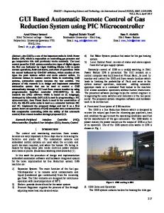
Mohd Suhaimi B. Sulaiman et. al. / (IJCSE) International Journal on Computer Science and Engineering Vol. 02, No. 04, 2010, 1401-1405
GUI BASED REMOTE ON/OFF CONTROL AND MONITORING SINGLE PHASE LAMP USING MICROCONTROLLER Mohd Suhaimi B. Sulaiman Faculty of Electrical Engineering Universiti Teknologi MARA (UiTM) 23000 Dungun, Terengganu, Malaysia
[email protected]
Shaza Rina Bt Sahamir Faculty of Architecture, Planning & Surveying Universiti Teknologi MARA (UiTM) 94300 Kota Samarahan, Sarawak
[email protected]
Gopala Krishnan Sekharan Nair Academy of Language Studies Universiti Teknologi MARA (UiTM) 23000 Dungun, Terengganu, Malaysia
[email protected]
Abstract—Microcontrollers are very popular in electronics and computer-controlled systems worldwide. This paper presents the control of a microcontroller-based system using the computer and explains comprehensively the hardware and software parts of the microcontroller. Peripheral Interface Controller (PIC) software developed by Microchip (MPASM) is used in programming a PIC microcontroller, and Visual Basic is used in programming the user interface. The developed system showed that the auto-switching mode of transmission could be implemented via the PIC microcontroller and an RS485 transceiver. The PIC microcontroller is chosen to implement the control unit due to its advantages such as high speed, Harvard and Reduced Instruction Set Computer (RISC) architecture, low cost and flexibility for programming. The controller unit used in the mentioned processes is designed. The developed system showed that the Graphical User Interface (GUI) and the microcontroller successfully switched on and off a single-phase lamp via twisted pair cables. Keywords Peripheral Interface Controller (PIC); Microcontroller; Graphical User Interface (GUI); Remote; Control
I.
INTRODUCTION
Remote controlling and monitoring machines are important fields of study these days. The whole process of supervising, controlling and monitoring electrical devices and equipments from electric power stations and the distribution
ISSN : 0975-3397
Zawawi bin Ismail@ Abdul Wahab Faculty of Computer and Mathematical Sciences Universiti Teknologi MARA (UiTM) 23000 Dungun, Terengganu, Malaysia
[email protected]
Nazrul Nadziruddin bin Mohd Zameri Academy of Language Studies Universiti Teknologi MARA (UiTM) 23000 Dungun, Terengganu, Malaysia
[email protected]
Kamaruzaman Jusoff TropAir, Faculty of Forestry Universiti Putra Malaysia 43400 Serdang, Selangor, Malaysia
[email protected] grids is based on automation, protection, data acquisition and equipment control. A popular application in this field, which is in highly demand, involves controlling the power equipment in the building, such as the motor, heater, lamp and airconditioner. The problem of power management is the remote control adjustment, which is a result from consumers’ carelessness. Microcontrollers are suitable in low-cost control applications. The main feature of the system is the use of programmable integrated circuits (PICs) to perform direct control [1]. There are many tradeoffs that are addressed during the control system design, of which control allocation is an integral part, dictate the need for a reliable, computer-based design tool [2]. The potential for such systems to provide a low cost, yet powerful process management tools, is becoming increasingly evident, particularly given the ever-improving capabilities of microcontrollers [3]. The proposed system architecture, considering both the hardware and software elements involved is essential in this new era [4]. There is no doubt that the use of technology in the metering department has been on the rise. Since the days when electro-mechanical devices were used in the early 20th Century, the scenario has undergone much transformation [5]. Automation and remote control systems have been introduced to help and protect workers from hazardous working environments [6]. SMS technology is an example of remote control technology. This
1401
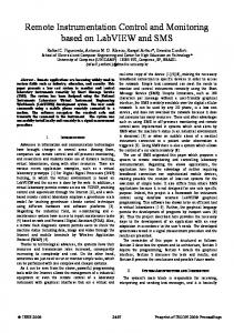
Mohd Suhaimi B. Sulaiman et. al. / (IJCSE) International Journal on Computer Science and Engineering Vol. 02, No. 04, 2010, 1401-1405 technology could be used as a cost effective and more flexible way of monitoring and controlling. SMS technology utilizes a system which is developed to control and monitor electric circuitry using the PIC16F877A through remote means. The microcontroller performs all functions of the system above [7]. This paper explains how the central station (Fig. 1) works as a local or field bus device that controls all the other units. A person in a room uses a computer to control these units. All the functions are developed by a PIC 16F877 microcontroller. The software uses Visual Basic to monitor and control the lamps. This paper reports how to develop and design an asynchronous serial data communication link between the site and central station using a microcontroller and to build a low cost GUI based remote on/off control. II.
III.
MINIMUM CIRCUITRY FOR 16F877
The PIC 16F877 microcontroller with 8-kilobyte Flash Program Memory is used in this study. It has 368 bytes RAM (Random Access Memory), Timers, 10-bit Analog to Digital Converters and 33 I/O (Input and Output) ports. The minimum circuitry for 16F877 is indicated in Figure 2. Figure 2 shows that a 20MHz Crystal and 33pF capacitors are used for Oscillation. Port 1 is the Master Clear input which can reset the PIC.
METHODS & MATERIALS
Max232 pins
RS232 pins
The hardware development of the GUI Based Remote On/Off Control and Monitoring Single Phase Automation Device is as shown in Figure 1. The system consists of a personal computer (PC) as a main controller that combines the RS 232 and RS 485 converter with the PIC16F877 microcontroller circuit system which acts as a slave unit. The proposed technique of centralization utilizes a concept of master/slave communication. In this system, one master device controls the other slave units. All these slave units have their own unique identification address. When the slave units receive the same address data, they extract the address from the master and compare it with their identification address. The slave units with matching addresses will send back the address to the master devices for confirmation for a successful transfer. This is aided by an auto handshaking line driver for transmitting and receiving which is controlled by the PIC16F877 microcontroller. The slave units are controlled using the PIC16F877 microcontrollers, which provide serial-embedded communication to external RS-485 link configurations through the software. Output and input devices that include the lamp circuit as well as the RS 485 transceiver are directly hooked to the microcontroller, thereby, minimizing the space used by the system.
Figure 2. Minimum circuitry for 16F877
The PIC microcontrollers used require either the TTL (Transistor Transistor Logic) or CMOS logic levels. The first step to connect the microcontroller to the RS-232 port is to transform the RS-232 levels back to 0 and 5 Volts and this is made possible by using the common level converter such as the MAX-232 Level Converters. The connection of MAX-232 to the computer is indicated in Figure 3. The RX/TX (Receiver and Transmitter) pins of Max232 are connected to the RX/TX pins of the microcontroller.
Central station (Computer)
Max485 pins
Twisted-pair wire
PIC 16F877
Max485
Driver Circuit
Driver Circuit
Driver Circuit
Driver Circuit
Relay
Relay
Relay
Relay
Lamp 1
Lamp 2
Lamp 3
Lamp 4
AC
Figure 3. Connection between Max232 and computer Figure 1. Hardware development of the GUI Based Remote On/Off Control and Monitoring Single Phase Automation Device
ISSN : 0975-3397
1402
Mohd Suhaimi B. Sulaiman et. al. / (IJCSE) International Journal on Computer Science and Engineering Vol. 02, No. 04, 2010, 1401-1405 IV.
HARDWARE DESIGN
The slave unit is controlled using the PIC16F877 microcontrollers as shown in Figure 4. The microcontrollers enable various functions of ports such as digital input or output ports. Additionally the analog input ports and USART (Universal synchronous asynchronous receiver transmitter) port for serial communication are also regulated by the microcontrollers. 5v 10k
5v
+5v Reset RC3 RC4
1K
5v PIC16F877
5v
100nF
33pF 20MHZ 33pF
1 2 3 4
RC7 RC6
2
D2
Buzzer
11 12 13 14
8
9
32 31
LTC485
1 100nF
D1
8 7 6
To RS485 to RS232 converter
5
100nF
RD7 RD6 RD5 RD4 RD3 RD2 RD1
Figure 5. Flowchart of programming in PIC microcontroller used to turn lamps ON or OFF
10 RD0
Figure 4. Schematic diagram of the proposed slave unit controller
To fulfill the requirement of the centralization process, a prototype system is developed. This system has four slave units all with the similar hardware configurations and all controlled by the microcontroller. The system is clocked with a 20-MHz external crystal oscillator that produces a faster execution time to accomplish one instruction cycle compared to a lower frequency crystal oscillator. A five-volt DC supply voltage is required for the operation of the hardware system. To protect against unwanted noise, a 100nF capacitor is placed across the power supply and the capacitor is also grounded. V.
SOFTWARE DESIGN
The whole process of controlling the hardware system is implemented by the PIC assembly language programming. This includes fixing the threshold setting point, preparing ADC (analog to digital converter), producing a desired delay, controlling the current driver circuit and providing interchangeable serial data transmission technique using an embedded USART(). A Computer aided design (CAD) which provide the supporting tools for simulation, testing and debugging of the program is provided by MPLAB IDE® software which was developed by Microchip Corporation®. The flow chart of programming the PIC is indicated in Figure 5 below.
ISSN : 0975-3397
VI.
EXPERIMENTAL RESULT
The system, based on Windows platform, performed successfully in transmitting serial data between the computer and the microcontroller. The GUI, based on Windows platform, provides the use of the USB computer port to the system. The GUI which was developed for monitoring is based on remote ON/OFF single-phase lamps. VII. GUI BASED ON WINDOWS PLATFORMS Most computers today are developed with Universal Serial Bus (USB) for connection with peripheral devices. One of the popular programs to support the USB communication port of a computer is the programming provided by GUI using Microsoft Visual Basic. Microsoft designed it for graphical user interface programming which is different from a general purpose programming language and procedural language. Microsoft calls Visual Basic an event driven programming language. Since the sequence of events that a user chooses is practically unlimited, the programmer must code each event independently in such a way that it can interact with other events. VIII. DEVELOPMENT OF GUI USING VISUAL BASIC Figure 6 shows the flowchart for the development of GUI using Visual Basic. A mouse is used to send the ASCII code by clicking the provided command buttons on the GUI. The program starts by reading the set up process initialized for serial transmission before GUI can be interfaced with either an RS232 serial device or a USB to RS232 converter.
1403
Mohd Suhaimi B. Sulaiman et. al. / (IJCSE) International Journal on Computer Science and Engineering Vol. 02, No. 04, 2010, 1401-1405 S ta rt
Is a d d re s s fo r O N L1?
S e ttin g th e G U I fo r tra n s m ittin g d is p la y in g d a ta
NO
NO Is a d d re s s fo r O FF L1?
YES
Is a d d re s s fo r O N a ll LA M P?
YES
ON LAM P 1
YES
OFF LAM P1
O N A LL LAM PS
S e ttin g th e p ro c e s s fo r In te rfa c in g G U I w ith s e ria l d a ta Is a d d re s s fo r O N L 2 ? NO
a d d re s s d a ta send ?
NO
YES
Is a d d re s s N O fo r O F F L 2 ?
Is a d d re s s fo r O F F a ll LA M P?
YES
O N LAM P2
NO
OFF LAM P2
NO
YES
O FF ALL LAM PS
YES NO Is a d d re s s fo r E X IT ?
NO
Is a d d re s s fo r O N L3? YES
YES
O N LAM P3
E x it p ro g ra m
NO Is a d d re s s fo r O FF L3? YES
OFF LAM P3
Figure 6. Flowchart of graphical user interface for Windows platforms
The GUI uses the command buttons to activate the selected port of the microcontroller that controls the ON/OFF of single-phase lamps. Every command button on the GUI represents the ASCII code from the keyboard. The program waits for another ASCII code to be entered by the mouse. The command “Stop Operation” terminates the whole program. The development of the GUI based on Windows platforms for monitoring and remote ON/OFF control is shown in Figure 7.
improve communication speed and simultaneously support the attachment of multiple devices. The USB-to-RS232 converter is used for interfacing with the USB port of the computer to the system developed. The driver of USB-to-RS232 converter initializes the USB port as a serial port protocol. The use of the converter from a serial interface to the USB port will release a serial communication port to other applications. This allows the devices to be unchanged, making the converter responsible for treating the differences between the protocols. This converter is responsible for transmitting ASCII (American Standard Code for Information Interchange) data from GUI to microcontroller. COMMAND BUTTON’S CHARACTER FROM GUI BASED REMOTE ON/OFF The command buttons are used to control the operation of single-phase lamps. In this study, two lamps are monitored based on the remote ON/OFF of 240V single-phase lamps. The command buttons, ON LAMP1 and ON LAMP2 are used to switch on lamp 1 and lamp 2 respectively while the button OFF LAMP1 is used to switch off lamp 1 and the button OFF LAMP2 to switch off lamp 2. The ON ALL LAMPS button is used to switch on both lamps and the button OFF ALL LAMPS button to switch off both lamps. X.
XI.
COMMAND CHARACTER USED TO SWITCH ON LAMP
Figure 8 shows the ASCII ‘w’ character received on the MAX-232 port sent by the command button “ON LAMP1”. The command button “ON LAMP1” represents the ASCII code ‘w’ for switching on lamp 1 that is controlled by the microcontroller. The microcontroller compares its reference ASCII code character with the data received and switches on the switching transistor when the data received matches the reference ASCII code character saved in the microcontroller.
Figure 7. The graphical user interface
IX.
INTERFACING SERIAL AND USB PORT
The communication port between the GUI and singlephase lamp units of the microcontroller can be interfaced either directly via an RS-232 port or the PC USB port. Since computers today are developed with the USB (Universal Serial Bus) port, the GUI based on Windows platforms is designed to be capable of transferring and receiving data via such ports. The USB port of a personal computer is developed to assist the connection of peripheral devices to a computer, ISSN : 0975-3397
Figure 8. ASCII ‘w’ sent by GUI of command button “ON LAMP1”
Since the data is transmitted using an asynchronous form, the start bit and stop bit indicate the beginning and ending of the data. Figure 9 shows the ASCII character ‘w’ sent by GUI and the same ASCII character received at the microcontroller port. Channel 2 is in the TTL data format and channel 1 in the MAX-232 data format. The microcontroller detects data in the TTL form, which is compatible for the USART 1404
Mohd Suhaimi B. Sulaiman et. al. / (IJCSE) International Journal on Computer Science and Engineering Vol. 02, No. 04, 2010, 1401-1405 microcontroller. The data sent through the RS-232 from a personal computer (PC) is converted to TTL format by RS-485.
The effect of lines transmission is tested using different lengths of cables. It is proven that the twisted-pair lines had successfully transmitted asynchronous data from GUI to the microcontroller over 400m of cables used. Adding the fail-safe biasing resistors accords the line transmission in a known-state and reduces the resonant effect on the signal lines. The parallelterminated resistors are better at improving the signal of the twisted-pair. It can be concluded that utilizing both techniques increases the reliability of the system performance. GUI provides the process for transmitting the ASCII character data. It is shown that GUI using the Visual Basic program, performed excellently in transmitting data to the microcontroller. It can be concluded that GUI using Visual Basic can be interfaced with both RS232 and the USB port of a computer.
Figure 9. ASCII character ‘w’ of command OFF ALL LAMP1
ACKNOWLEDGMENT
XII. DISCUSSIONS
The authors would like to express their deepest appreciation to Aileen Farida Mohd Adam for her contribution and support in the development of this paper.
The GUI command buttons of ASCII characters control the transmitted signal to the single-phase lamps. The GUI command buttons using the ASCII characters communicate successfully with the microcontroller to activate the lamps. The use of a shorter cable produces a better shape of binary data flow over twisted-pair cables. The longer cable will cause a resonant effect in the twisted-pair cable that is not removed completely. The longer the length of the cable used, the more will be the external fail-safe biasing and terminations that will be needed to stabilize the binary data which is needed in the twisted-pair for reliable data transmission.
REFERENCES [1] [2]
[3]
[4]
XIII. CONCLUSIONS The GUI based remote ON/OFF and monitoring singlephase lamps are presented in this study. All relative work pertaining to the completion of the study, which covers the development of GUI based remote ON/OFF system, programming and designing of microcontroller units for controlling single phase lamps, and the effect on longer cables on twisted-pair transmission which have been demonstrated and described. The functions and performance of the system are tested using the incandescent lamps. The developed system shows that GUI and the microcontroller perform successfully to switch on and off the single-phase lamps via twisted pair lines.
ISSN : 0975-3397
[5]
[6]
[7]
C. D. Johnson, “Process Control Instrumentation Technology”, Prentice Hall, Englewood Cliffs, NJ, 1997. M.R. Frankowiak, R.I. Grosvenor, and P.W. Prickett, “MicrocontrollerBased Process Monitoring Using Petri-Nets”, EURASIP Journal on Embedded Systems, vol. 2009, Article ID 282708, 2009. S. R. D. Kalingamudali et al., “Remote Controlling and Monitoring System to Control Electric Circuitry through SMS using a Microcontroller”, Industrial and Information Systems, First International Conference on Industrial and Information Systems: Peradeniya, Sri Lanka, 8-11 August, 2006. pp. 378-382. M. L. Glaze, “The Design and Implementation of a GUI-Based Control Allocation Toolbox in the MATLAB® Environment”, Msc. Thesis, Virginia Polytechnic Institute and State University, Blacksburg, 85 p. 2008. T.S.Y. Moghavvemi, “PIC-based automatic meter reading and control over the low voltage distribution network”, Student Conference on Research and Development : SCOReD 2002 : Globalizing research and development in electrical and electronics engineering, July 16-17, 2002, Grand Blue Wave Hotel, Shah Alam, Malaysia. pp. 517-520. O. González, M. Rodríguez, A. Ayala, J. Hernández & S. Rodríguez, “Application of PICs and microcontrollers in the measurement and control of parameters in industry” in International Journal of Electrical Engineering Education, 41/3, 2004, pp. 266-274. A. Premadi, M.S. Ab-Rahman, B.C. Ng, M. Saupe & K. Jumari, “Application of PIC microcontroller for online monitoring and fiber fault identification” in International Conference of Electrical Engineering and Informatics, ICEEI '09, 5(7), 2009, pp. 463-467.
1405