Halmstad University Hardware Design using VHDL IDE Lab 2 10-06 ...
Recommend Documents
The VHSIC Hardware Description Language (VHDL) was created for the
purposes of ... Ashenden, P. J., The Designer's Guide to VHDL (2nd Edition),
Morgan ...
VHDL (Very. High Speed Integrated Circuit Hardware Description Language)
promises to ease the design and verification of complex digital circuits by ...
CS/CoE0447: Computer Organization and Assembly Language. University of ...
The three hardware designs we saw are based on the notion g of “restoring ...
The Student's Guide to VHDL, Peter J. Ashenden, Morgan Kaufmann, 1998. 3. ...
Most of the homeworks are mini-projects and require VHDL programming and ...
proprietary languages owned by PLD manufacturers. 3. Using VHDL. ▫ Using
VHDL to program a digital logic design. □Define What the program is going to do
.
o BIT_VECTOR â is a vector of bit values (e.g. BIT_VECTOR (0 to 7) ... For the example of Figure 1-2 above, the entity declaration looks as follows. --ENTITY ...
Conference on Information Technology Based Higher Education and ... Abstract - Business and Information Technology are highly ..... ââInternational Master''s.
both a proactive and a reactive way of orchestrating, the model proposes a ..... the digital landscape where business roles might rapidly change (Van de Ven, ..... velopers can use Apple and Android app stores and marketplaces to launch their ...
Dec 8, 2018 - [6], who showed a strong (r ⥠0.6) relationship between positive ..... Scatter plot of the relationship between PC5 score and jump height (R2 ...
Aug 13, 2015 - 2.6 The industrial marketing and purchasing (IMP) perspective ................. 49 .... Chapter 5 - Empirical Findings: Innovation of e-Safe ........... 89.
1. EE366 – CMOS VLSI Design. Hardware Description Languages. Basic
Reference for VHDL. • Reference book: – VHDL by Example by Douglas Perry ...
Codesign and Parallel Processing Laboratory. Seoul, Korea ... us to evaluate each design decision such as partitioning or ... Since, the software part is running as a UNIX process, most of our ef- forts for ... U.C.Berkeley[8] devised a common interf
Aug 20, 2009 ... Hardware Design with VHDL. Course Introduction. ECE 443. ECE UNM. 2. (8/20/
09). Course Goals. Simply stated, my objective is to teach you ...
With force transducers and a rotary potentiometer gait ... During the contact phase the stiffness was set to zero to avoid ..... converter. The signal was smoothed by a first order analog low- pass filter with cut-off frequency of 50 Hz. The MR- ...
Will be covered in more detail with sequential VHDL design ...... td l i t (7 d t 0)
signal a : std_logic_vector(7 downto 0);. ▫Another form (less desired, do not use).
May 14, 2012 - in limited budget for on-board sensors and the amount of .... to a central server. There, they .... of dedicated sensors is also a problem: neither of.
An integrated development environments (IDE) like NetBeans incorporates many
tools to facilitate creating, managing and running a program, including things ...
Using NetBeansTM IDE 5.5. Your Guide to Getting Work Done in NetBeans IDE.
Welcome to the Using NetBeans™ IDE 5.5 guide. This guide is designed to give
...
This paper suggests a cluster collision avoidance mechanism and a dual transceiver architecture to be used in a clustered wireless multihop network. These two.
and Run-dang YANG, et al. REFERENCES. [1] Jun-qi YAN, Xiu-min FAN, Deng-zhe MA, et al. Theory, technical foundation and practice of virtual manufacturing.
Self-organizing maps for automatic ... Abstract⯠A telematic based system for enabling automatic ... Halmstad, Box 823, 301 18 Halmstad, Sweden (e-mail:.
polarization of the wave depends on the local fiber orientation in the sample. ... vibration harmonics in the plant. The most ... [6], King [7], Forrer and Funck [8]).
Logic Circuit Lab. Lab #5; Page 1/3. Spring 2003. Combinational Circuits Using
VHDL ... The text book Digital Design: Principles and Practices, 3rd Edition by ...
An integrated development environments (IDE) like NetBeans incorporates many
tools to facilitate creating, managing and running a program, including things ...
Halmstad University Hardware Design using VHDL IDE Lab 2 10-06 ...
1. Hardware Design using VHDL. Lab 2. 1. Purpose. The lab should provide
training in the use of VHDL for description and simulation of digital circuits. 2.
VHDL.
Halmstad University IDE
Hardware Design using VHDL Lab 2 10-06-29
Hardware Design using VHDL Lab 2 1. Purpose The lab should provide training in the use of VHDL for description and simulation of digital circuits. 2. VHDL VHDL is a language for description of digital circuits. VHDL is a standardized language that allows description of digital circuits behaviour and structure of various abstraction levels and is a very comprehensive language. There are simulators for circuits described in VHDL. Here, we use Active-HDL from Aldec. Synthesizing is compared with simulation more complex. We are using Synplify Pro from Synplicity. 3. Preparation Read Sjoholm-Lindh: VHDL for Designers chapter 3, 4 and 9. Read the lab-PM. Perform design work for problem 1-2. 4. Exercises Laboratory contains two tasks, a combinatorial task and a sequence task. Problem 1: ALU Function and performance: Design a simple ALU using a FPGA. The system has two operands as inputs operands and one operational code. The input data is connected via DIP switches on the system board. The ALU will receive two 3-bit binary numbers, X = and Y = . It also have two control signals, OP = , to perform four different operations. The 3 +3 operand bits and 2 operational bits are taken from the DIP switches on the system board. The outputs, 7 +7 bits, are connected to the 7-segment displays LED1 and LED2. A result is calculated depending on the operand values and the operational code. The result will be presented on the LED displays. As an input to the system will be changed, the results will be changed. Operational codes: 00 addition of the two 3-bit operands 01 multiplication " " 10 bitwise AND 11 bitwise XOR The results obtained in binary form. Presentation of the results on the displays both in hexadecimal form, and in decimal form. The choice between hexadecimal and decimal form is made with one of the push button switches. In order to present the results on the displays in decimal form a conversion from binary code to decimal form take place. Perform this transformation and present the results on the displays.
1
Halmstad University IDE
Hardware Design using VHDL Lab 2 10-06-29
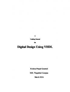
Problem 2: Codelock Function: The key (depicted below), will be simulated with six DIP switches. Five DIP switches (DIP4-DIP8) give the code, the sixth DIP switch (DIP1) recognizes that the key is fully inserted in the lock. When the key is in (DIP1 ='1 ', the signal-key ='1') will open the electronic lock if the code combination is right. Open the lock means that the output from the electronics module will go low (open signal ='0 '). This is shown by the LED (pin A9). After three attempts with invalid code the lock will be inactivated and give an alarm signal. This can be indicated by a segment on one of the displays. In this case it is not possible to open the lock with the correct code. The lock is inactive until it will be activated. The lock is activated with a zero on one input (signal resetn ='0 '). For this, use the Push Button SW6. The code is assumed to be fixed (built into the logic). The number of combinations is low (32), so the lock will not be approved by the insurance companies. It is easy to increase the number of fields and thus get a more secure lock. The code in this case is 01101. You may choose the combination of your design. Only zeros or only ones are not allowed.
______________________________________________________ X
X
DIP1
DIP4
X
X
X
DIP5 DIP6 DIP7
X
X
DIP8
Execution The design will be simulated, synthesized and implemented in a gate array and tested on the system board. Principle layout of the lock inputs and outputs.
Code from the lock (code(4:0)) (DIP4-DIP8) Key in lock (key) (DIP1)
Open lock (open) (LED)
Electronics
Alarm (alarm) (segment on display)
Enable lock (resetn) (SW6) The function will be described using a state machine.