to monitor and manage the network bandwidth. ... Two types of software can be distinguished. First .... the monitor/supervisor node and the DCSMonitor software.
Hands-on Course in Networked Control Systems Josep M. Fuertes, Ricard Vill`a, Jordi Ayza, Pere Mar´es, Pau Mart´ı, Manel Velasco, Jos´e Y´epez, Gina Torres and Miquel Perell´o
Abstract— This paper presents a hands-on course in networked control systems (NCS) to be integrated in the education of embedded control systems engineers. The course activities have a strong practical component and most of them are applied exercises to be implemented in a NCS setup. The paper describes the experimental setup and then proposes several activities that can be shaped into a course program according to the needs and diverse background of the targeted audience.
Fig. 1.
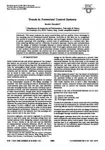
Experimental platform setup for each student group.
I. INTRODUCTION Networked control systems [1], [2] are gaining increased attention in many control application areas while the underlying control theory is starting to offer mature and methodological results, e.g. [3], [4]. In a parallel track, since the economic importance of embedded systems has grown exponentially, embedded systems education is becoming an strategic asset and there is a need for including NCS courses in the education of embedded systems engineers. The traditional teaching approach to the diverse disciplines involved in NCS such as control systems, real-time computing and communication systems, can be often quite math-intensive and abstract, thus failing to introduce students to the realities of NCS implementation. Hence, laboratory activities are crucial to consolidate the diverse theoretical material. To this end, this paper presents a hands-on course in networked control systems to be integrated in the education of embedded control systems engineers. The course activities have a strong practical component and most of them are applied exercises to be implemented in a NCS setup. This course can be taken as a complimentary material to other exiting courses in NCS and to other initiatives related to NCS education such as the Networked Control Systems Repository [5] or the NCS wiki page course Introduction to Networked Control Systems [6], to name a few. The proposal in this paper extends to a networked setup a previously presented laboratory experiment targeting microprocessor-based realtime control systems [8]. And extended report describing this course can be found at [9]. II. BACKGROUND ON NCS NCS take different forms, and two major types of control systems can be identified: shared-network control systems This work was supported by Spanish Ministerio de Educaci´on y Ciencia Project ref. CICYT DPI2010-18601. The authores are with the Automatic Control Department, Technical University of Catalonia, Pau Gargallo 5, 08028 Barcelona, Spain
{josep.m.fuertes, ricard.villa, jordi.ayza, pere.mares, pau.marti, manel.velasco, jose.yepez, gina.torres}@upc.edu
and remote control systems. The hands-on course proposal targets the first type, although several concepts can also be applied to the second type. The NCS considered for this course has several control loops, each one formed by a sensor, a controller and an actuator implemented in physically separated nodes, sharing a single broadcast domain to exchange the control data required for each control loop operation. For a given networked closed loop system, each operation would require sending the sensor reading in the sensor message after sampling the plant, and sending the control signal in the control message after computing its value in the controller node using the information found in the incoming sensor message. The most common design and implementation approach for NCS consists in the periodic execution of the control algorithm, which implies that messages from sensors to controllers and from controllers to actuators are periodic [10]. The course will cover these methods, but will also tackle other approaches that go beyond the periodicity of the standard approach, such as rate adaptation techniques to improve the aggregated control performance, e.g. [11], [12], or event-based sampling techniques to minimize bandwidth utilization while still guaranteeing stability and acceptable control performance, e.g. [13], [14]. III. EXPERIMENTAL SET-UP The basic scheme for the experimental platform for each student group is illustrated in Figure 1. It implements a twonode NCS in which one node acts as a controller (left node) while the other node acts as a sensor and actuator (right node) and it is attached to the plant. The reason for putting together the sensor and actuator in the same node is to save hardware resources. The controlled plant and processing platform (hardware, real-time operating system, and network) have been carefully selected to have a friendly, flexible, and powerful experimental set-up. Many controller design methods rely on the accuracy of the plant mathematical model. The more accurate the model,
Fig. 2.
Controller-sensor/actuator hardware for each student group
the more realistic the simulations, and the better the observation of the effects of the controller in the implementation. Hence, the plant was selected among those for which an accurate mathematical model could easily be derived, such as an electronic circuit (as argued in [8]). In particular, a simple electronic circuit in the form of a double integrator (DI) was selected because of the relative simplicity of its components together with the fact that the inherent unstable dynamics makes the control more challenging. The processing platform consists of the hardware platform, the real-time operating system and the network. As hardware platform, a micro-controller based architecture was selected because NCS are typically implemented using this type of hardware. As discussed in [8], for the processing platform, adopting the Flex board [15] (in its full version) equipped with a Microchip micro-controller dsPIC33FJ256MC710 represents a good compromise between cost, processing power, and programming flexibility. Regarding the real-time operating system, Erika Enterprise real-time kernel [15] was selected because it provides full support for modern scheduling algorithms [16]. Looking at the network, the CAN (Controller Area Network, [17]) protocol that was originally designed for the automotive industry, but it has also become popular in industrial automation as well as other applications, has been selected. CAN provides the basis for many cost-effective distributed embedded applications, and its properties and functionality such as reliability, dependability, or clock synchronization, are being constantly enhanced. Once the platform is ready, the networked setup for each student in the form of a tower of two flex boards looks like as in Figure 2. The bottom Flex board acts as a (remote) controller, and communicates via CAN with the top Flex board, that acts as a sampler and actuator, and it also contains the plant1 . A daughter board incorporating the DI circuit and CAN communication is plugged into the top Flex board. The same daughter board is plugged into the bottom Flex board, just for CAN communication purposes. Finally, 1 Note that with the same hardware, micro-processor based control can also be tested. In this case, the bottom board is not used, and the top board performs sampling, control algorithm computation and actuation.
Fig. 3.
Scheme of the overall networked control system.
Fig. 4.
Example of networked control system.
the bottom flex board has another daughter board enabling RS232 communication for monitoring. The modular architecture design permits networking all student setups in a single CAN network. In this way, a full NCS can be built, where several nodes acting as controllers, sensors and actuators control different DI systems. In addition, another node can be added to the network acting as a monitor/supervisor. The hardware of this node is again a full Flex board, equipped with the two same daughter boards, one with CAN and the other with RS232. Its role is to gather information of the state of all control loops, and to monitor and manage the network bandwidth. This node would be mainly used for the instructor/teacher, although it can be also used by students. A complete NCS with N control loops together with the supervisor/monitor is shown in Figure 3. Each group, that would correspond to the setup shown in Figure 2, is connected via CAN. Figure 4 shows an example of the full NCS with two groups, together with the monitor/supervisor node. Note that one of the groups has the controller-sensor/actuator hardware and the monitor hardware plugged together in a 3-board tower (on the right). IV. SOFTWARE Two types of software can be distinguished. First, the one that goes to each node (Flex board), also named Erika codes, and second, the one that can be run in an external PC for monitoring purposes, that is called
CPU mySystem { OS myOs { ... TASK TaskReferenceChange { REL_DEADLINE = "0.005s"; PRIORITY = 3; STACK = SHARED;SCHEDULE = FULL;}; TASK TaskController { REL_DEADLINE = "0.05s"; PRIORITY = 3; STACK = SHARED; SCHEDULE = FULL;}; COUNTER myCounter; ALARM AlarmReferenceChange { COUNTER = "myCounter"; ACTION = ACTIVATETASK { TASK = "TaskReferenceChange"; };}; ALARM AlarmController { COUNTER = "myCounter"; ACTION = ACTIVATETASK { TASK = "TaskController"; };}; }; Fig. 5.
Configuration file (conf.oil) for the controller node
TASK(TaskReferenceChange){ if (r == -0.5){r=0.5; LATBbits.LATB14 = 1; }else{ r=-0.5; LATBbits.LATB14 = 0;} Send_Controller_ref_message(&r);} TASK(TaskController){ x0=*(p_x0);//Get state x[0] from CAN msg x1=*(p_x1);//Get state x[1] from CAN msg x_hat[0]=x0-r*Nx[0]; x_hat[1]=x1-r*Nx[1]; u_ss=r*Nu; u=-k[0]*x_hat[0]-k[1]*x_hat[1]+u_ss; Send_Controller2Actuator_message(&u);} int main(void){ Sys_init(); SetRelAlarm(AlarmReferenceChange,1000,1000); for (;;); return 0;} Fig. 6.
Main parts of the code.c for the controller node
“DCSMonitor” in Figure 3. The node codes, the DCSMonitor, and other information related to this hands-on course are available at http://code.google.com/p/ pfc-platform-test/source/browse/. A. Main Software in NCS Nodes The description of the Erika codes is ordered according to the three type of nodes: controller, sensor/actuator, monitor/supervisor. For each node, the kernel configuration file conf.oil specifies the main parameters for the dsPIC and realtime kernel, and the code.c contains the main functionality. Due to space limitations, the following subsections give a non-detailed overview of each code. 1) Controller Node: The configuration file is shown in Figure 5. Among different specifications, it defines two tasks, TaskReferenceChange and TaskController, which are implemented in the code.c and associated to an alarm to control their periodicity of execution. The code.c file has three main parts (Figure 6): the main, and the two tasks defined in the conf.oil. The main configures the TaskReferenceChange whose role is to create a reference signal to be tracked by the controller. The
TASK(TaskSensor){ LATBbits.LATB14 ˆ= 1; Read_State(); Send_Sensor2Controller_message(&x[0]);} TASK(TaskSensor_supervision){ LATBbits.LATB14 ˆ= 1; Read_State(); Send_Sensor2Supervisor_message(&x[0]);} TASK(TaskActuator){ u=(*p_u); Get state u from CAN msg PDC1=((*(p_u))/v_max)*0x7fff+0x3FFF;} TASK(TaskSupervision){ /* It sends data via RS-232 to the PC} int main(void){ Sys_init(); SetRelAlarm(AlarmSensor,1000,50); SetRelAlarm(AlarmSupervision, 1000, 10); SetRelAlarm(AlarmSensor_supervision, 1000, 10); for (;;); return 0; } Fig. 7.
Main parts of the code.c for the sensor/actuator node
TASK(TaskControllerMonitor){ x0=*(p_x0);//Get state x[0] from CAN msg x1=*(p_x1);//Get state x[1] from CAN msg} TASK(TaskSensor_supervision){ x0=*(p2_x0);//Get state x[0] from CAN msg x1=*(p2_x1);//Get state x[1] from CAN msg} TASK(TaskActuatorMonitor){ u=(*p_u); x0=*(p_x0);//Get state x[0] from CAN msg x1=*(p_x1);//Get state x[1] from CAN msg} TASK(TaskSupervision){ /* It sends data via RS-232 to the PC} TASK(TaskToggleLed){ LATBbits.LATB14 ˆ= 1;//Toggle orange led} TASK(TaskCANUseless){ Send_CAN_useless();} int main(void){ Sys_init(); init_devices_list(); for (;;); return 0; } Fig. 8.
Main parts of the code.c for the monitor/supervisor node
TaskReferenceChange code simply generates a square wave that switches from −0.5v to −0.5v each second, and this information is sent over CAN for monitoring purposes. The TaskController is activated by interrupt upon reception of the sensor message delivered over CAN. It gets the plant state from the incoming message, implements a control law (in the figure a state-feedback controller with a tracking configuration), and sends the computed control signal over CAN in the control message. 2) Sensor/Actuator Node: The sensor/actuator node configuration file is similar to the one in the controller node. However, it defines different tasks that are coded in the corresponding code.c file partially shown in Figure 7. In the main, the periodicity for the sensor task is 50ms and the periodicity for the supervision tasks are 10ms. Note that the periodicity of the actuator task is not defined because it is executed upon reception of the control message sent by the controller node. The TaskSensor reads the
Fig. 9.
plant state and sends this value in the sensor message over CAN. The TaskSensor supervision sends the plant state over CAN for monitoring purposes. Similarly, the TaskSupervision sends similar information through the RS232 port. Finally, the TaskActuator, upon reception of the control message, takes the control signal form the message, and applies it to the plant. 3) Monitor/supervisor Node: The conf.oil for this node defines several tasks that are coded in the code.c file partially shown in Figure 8. The TaskSupervision sends data over the RS232 port. The TaskActuatorMonitor mainly obtains the control signal for a given control loop, while the tasks TaskControllerMonitor and TaskSensor supervision obtain the state of a given plant. The TaskToggleLed blinks a led, and the TaskCANUseless is used to regulate the bandwidth of the network by sending dummy messages. Although not detailed here, the full code.c also implements the code that manages the interaction between the monitor/supervision node and the DCSMontior software, which communicate over RS232. B. DCSMonitor The DCSMonitor is a monitoring program that can be used by each student group to monitor its own control loop dynamics, but it has been mainly designed for the instructor/teacher to allow monitoring any of the active control loops, as well as to regulate the network bandwidth. Figure 9 provides a general view of the DCSMonitor. It can perform three main activities. First, it permits to monitor the number of control loops that are exchanging data over the network (Control links in the figure). It also displays the dynamics (reference signal, control signal and states) of a
DCSMonitor.
Signal SIGNAL SIGNAL SIGNAL SIGNAL
STOP MONITOR PERCENT DEVICES
Value 0x01 0x00 0x02 0x04
Meaning It cancels current actions To monitor a particular control loop To generate artificial load in the bus To list all active control loops TABLE I
C OMMANDS FROM DCSM ONITOR TO THE MONITOR / SUPERVISOR NODE
given control loop, either numerically or graphically. And finally, it has a slider bar that permits to regulate the number of dummy messages that are sent over the network to create different bandwidth loads. Note that in Figure 9, at time 82.7 s, the reference r has two values, while at time 83.7 s, the reference has no value. The same happens with u, x1 and x0. This is an issue related to the way the figure was captured. In execution, this problem is not present. To allow this functionality, the communication between the monitor/supervisor node and the DCSMonitor software over RS232 was configured two be bidirectional. On one hand, the DCSMonitor sends control commands to the monitor/supervisor node using a simple 8-byte frame coded according to an identifier, whose values and meaning are summarized in table I. On the other hand, the monitor/supervisor node sends to the DCSMonitor a more complete 71-byte frame in which the monitor/supervisor node communicates information about the control loop under supervision, as well as the list of active control loops if required. In the case that the DCSMonitor is used for a student group to monitor its own control loop dynamics, the information is sent by the sensor/actuator node of that particular control loop using a medium 23-byte frame. A scheme of this data exchange is shown in Figure 10, where the top sub-figure shows the
Fig. 10. RS232 communication between the monitor/supervisor node and the DCSMonitor. Top: teacher setup. Bottom: student group setup.
communication when the DCSMonitor is used by the teacher while the bottom sub-figure shows the communication when the DCSMonitor is used by a group of students. In order to allow the monitor/supervisor node to send accurate monitoring information to the DCSMonitor software over RS232, the CAN messages used in each control loop were coded following different guidelines. First, different levels of priority were required. In addition, it was required to be able to identify different control loops, and in each control loop, different message classes, and even subclasses. This has been achieved by coding each message identifier using different fields. V. C OURSE ACTIVITIES This section presents some of the activities to carry out in the hands on course using the presented setup. To start with, basic control theory may be needed to establish a common knowledge among all the students. It could include statespace system representation (in the continuous-time but more important in the discrete-time domain and including delays), discrete-time systems analysis (including topics such as controllability and observability, as well as sampling period selection), and control design by state feedback (starting with pole placement techniques and considering delays, together with observer and tracking structures) From this basic theory, simulation and implementation activities could include: 1) Open loop analysis: Using for example Matlab/Simulink for simulation and then the hardware setup, to obtain the open loop system response of the double integrator circuit in front of a reference signal in the form of a square wave.
2) Closed-loop design in the discrete-time domain: To design a state feedback controller using for example pole placement in the discrete-time domain (fixing the closed loop continuous-time poles) with tracking structure and assuming that both DI states variable are measured. Performance specifications may include that an stable circuit response must be achieved while hardware constraints such as actuator saturation must be avoided. In this case, the sampling period and closed-loop pole locations for the controller can be obtained by standard design guidelines and rules-ofthumb. Alternatively, it can be specified for example a period of h = 0.05 s, and to design a discrete state feedback controller placing the continuous closed loop poles at p1,2 = −5±20i, which meet the specifications. This can be simulated and implemented in the hardware setup. At this stage, different type of observers can be also covered. Note that the implementation will be subject to the CAN delay. 3) Delay effects in NCS: To simulate for example with TrueTime [18] the NCS for the DI using the settings for period and desired poles as before, with sampling occurring in the sampler node, control algorithm executing in a controller node, and actuation taking place in the actuator node. As a network, CAN can be used with different baud-rates and then to analyze, by observing different responses, how the communication delay affects the performance considering that the controller that applies is the one obtained previously. Note that in this case, the delay is constant. The simulation study can also be implemented by each group, locally, using the NCS setup, and monitoring the response in the DCSMonitor using for example different CAN baud-rates or by increasing the CAN load using the slider bar of the DCSMonitor 4) NCS simple controller design: The degrading effects of delays can be treated using different approaches. A simple approach is to design the controller assuming an input delay in the system, which will result in extending the original state space system with a new state variable that represents the previous control signal [19]. This imposes to place a third discretetime pole for obtaining the state-feedback gain. It can be placed at 0. Then it can be noted that the application of this new controller is effective for a constant delay but not for the scenario of varying delay. As before, TrueTime can be used for simulation. And in the implementation, all the control loops from all the students can be networked together to study the effect of varying delays in the DI plants. 5) NCS advanced controller design: In order to design a controller capable of dealing with varying time delays, several strategies are available, including controlcentered approaches, e.g. [1], or implementation-based approaches, e.g. [20]. One or more of them can be simulated and implemented. In addition, using the latest results on rate adaptation techniques and on
set-up presented in this paper is being used at the Technical University of Catalonia in control and embedded systems courses at graduate, master, and PhD levels. It has also been the basis for the series of schools ARTIST Graduate School on RT Kernels for Microcontrollers of the ArtistDesign NoE [21]. R EFERENCES
(a) when bandwidth utilization is low
(b) when bandwidth utilization is high Fig. 11.
DI dynamics.
event-driven control listed in Section II, existing results that are able to increment control loops performance and/or to minimize CAN bandwidth utilization can be also simulated and implemented. Note that the last exercise can have different levels of difficulty and may require non-basic control and real-time systems theory for its correct simulation and implementation. By performing the previous activities students can implement a rich set of exercises. They will observe several DI dynamics according to the activity. Just for illustrative purposes, Figure 11 shows the DI response in the case of having different loads in the CAN network. As the network load increases, the response degrades. This rises questions like “why does the bandwidth utilization influences so much the response of the system?” and it further motivates the students learning process. VI. CONCLUSIONS This paper has presented a hands-on course in NCS to be integrated in the education of embedded control systems engineers. The course has a strong practical component, and emphasis has been placed in the description of the platform where to implement the diverse activities. Details of the code to be executed in each networked node have been explained and a new software to be executed in an external PC for monitoring purposes has been also presented. Finally, a set of course activities have been listed. The hardware/software
[1] J.P. Hespanha, P. Naghshtabrizi and Yonggang Xu, “A Survey of Recent Results in Networked Control Systems,” Proceedings of the IEEE , vol.95, no.1, pp.138-162, Jan. 2007 [2] R.A. Gupta and M.-Y. Chow , “Networked Control System: Overview and Research Trends,” IEEE Transactions on Industrial Electronics , vol.57, no.7, pp.2527-2535, July 2010 [3] D. Ne˘si´c and D. Liberzon, “A unified framework for design and analysis of networked and quantized control systems,” IEEE Transactions on Automatic Control, Vol. 54, No. 4, pp. 732–747, April 2009. [4] W.P.M.H. Heemels, A.R. Teel, N. van de Wouw, D. Ne˘si´c , “Networked Control Systems With Communication Constraints: Tradeoffs Between Transmission Intervals, Delays and Performance,” IEEE Transactions on Automatic Control, vol.55, no.8, pp.1781-1796, Aug. 2010 [5] Networked Control Systems Repository, http://filer.case. edu/org/ncs. [6] Course wiki page Introduction to Networked Control Systems, http://www.cds.caltech.edu/˜murray/wiki/index. php/EECI08:_Introduction_to_Networked_Control_ Systems. ˚ en, A. Blomdell, and B. Wittenmark, “Laboratories and real[7] K.-E. Arz´ time computing: integrating experiments into control courses,” IEEE Control Systems Magazine, vol. 25, no. 1, pp. 30-34, Feb. 2005. [8] P. Mart´ı, M. Velasco,J.M. Fuertes, A. Camacho, G. Buttazzo, “Design of an Embedded Control System Laboratory Experiment,” IEEE Transactions on Industrial Electronics, vol.57, no.10, pp.3297-3307, Oct. 2010 [9] J.M. Fuertes, R. Vill`a, J. Ayza, P. Mar´es, P. Mart´ı, M. Velasco, J. Y´epez, G. Torres and M. Perell´o, “Design of a Hand-on Course in Networked Control Systems”, Research report ESAII-RR-12-01, Automatic Control Department, Technical University of Catalonia, January 2012 [10] D. Hristu-Varsakelis and W. S. Levine, Handbook of Networked and Embedded Control Systems, Birkh¨auser Boston, June, 2008. [11] Ben Gaid, M.E.M.; Cela, A.; Hamam, Y., “Optimal integrated control and scheduling of networked control systems with communication constraints: application to a car suspension system,” IEEE Transactions on Control Systems Technology, vol.14, no.4, pp. 776-787, July 2006. [12] P. Mart´ı, A. Camacho, M. Velasco, M. El Mongi Ben Gaid, “Runtime Allocation of Optional Control Jobs to a Set of CAN-Based Networked Control Systems,” IEEE Transactions on Industrial Informatics, vol.6, no.4, pp.503-520, Nov. 2010 [13] A. Anta and P. Tabuada, “On the benefits of relaxing the periodicity assumption for networked control systems over CAN,”, Real Time Systems Symposium, December 2009. [14] X. Wang and M. Lemmon, “Event-triggering in distributed networked control systems”, IEEE Transactions on Automatic Control, vol. 56, no.3, pp.586-601, March 2011. [15] Evidence srl., http://www.evidence.eu.com/ [16] G. Buttanzo, Hard Real-Time Computing Systems: Predictable Scheduling Algorithms and Applications, Norwell, MA, USA: Kluwer Academic Publishers, 1997. [17] CAN Specification version 2.0. Robert Bosch GmbH, Postfach 30 02 40, D-70442 Stuttgart, 1991. [18] TrueTime: Simulation of Networked and Embedded Control Systems, http://www3.control.lth.se/truetime/. ˚ om and B. Wittenmark, Computer controlled systems, Pren[19] K.J. Astr¨ tice Hall, 1997. [20] C. Lozoya, P. Mart´ı, M. Velasco, J.M. Fuertes, “Analysis and design of networked control loops with synchronization at the actuation instants,” in 34th Annual Conference of IEEE Industrial Electronics, pp.2899-2904, 10-13 Nov. 2008 [21] ArtistDesign Network of Excellence, IST-2008-214373, http:// www.artist-embedded.org/artist/.