and its direct projections to the motor neurons of the spinal cord, some of which ..... source physical-engine interface software âOPALâ (Open. Physics Abstraction ...
Hierarchical Reinforcement Learning and Central Pattern Generators for Modeling the Development of Rhythmic Manipulation Skills Anna Lisa Ciancio, Loredana Zollo, and Eugenio Guglielmelli Biomedical Robotics and Biomicrosystem Lab, Università Campus Bio-Medico di Roma Via Álvaro del Portillo 21, I-00128 Roma, Italy {a.ciancio, l.zollo, e.guglielmelli}@unicampus.it Abstract—The development of manipulation skills is a fundamental process for young primates as it leads them to acquire the capacity to finely modify the world to their advantage. As other motor skills, manipulation develops on the basis of motor babbling processes, which are initially heavily based on the production of rhythmic movements. We propose a computational bio-inspired model to investigate the development of functional rhythmic hand skills from initially unstructured movements. The model is based on a hierarchical reinforcementlearning actor-critic model that searches the parameters of a set of central pattern generators (CPGs) having different degrees of sophistication. The model is tested with a simulated robotic hand engaged in rotating bottle cap-like objects having different shape and size. The results show that the hierarchical architecture of the model allows it to develop skills based on different combinations of CPGs so to suitably manipulate the different objects. Overall, the model shows to be a valuable tool for the study of the development of rhythmic manipulation skills in primates. Index Terms— Actor critic, humanoid simulated robotic hand, motor babbling, neural networks.
I. INTRODUCTION The development of manipulation skills depends on the maturation of the nervous system and developmental mechanisms, however the precise contributions of each process are not fully understood yet. This is in part due to an incomplete understanding of the maturation dynamics of different parts of the motor system (e.g. the pyramidal tract and its direct projections to the motor neurons of the spinal cord, some of which are proposed to underlie skilled movements of hand and digits [1,2], and in part to the knowledge gap on the learning mechanisms that lead to the development of manipulation skills [3]. This research focuses on the latter issue. During motor development infants perform a number of apparently unstructured movements (“motor babbling”, [4]) that since Piaget's theories on “circular reactions” [5] are thought to play a fundamental role in motor development. Although various models have been proposed to study motor babbling and its role in motor development, most of them (e.g., [6,7]) overlook the key fact that most movements produced during early motor babbling are rhythmic movements [8], not discrete movements (see [9] on the
Daniele Caligiore and Gianluca Baldassarre Laboratory of Computational Embodied Neuroscience, Istituto di Scienze e Tecnologie della Cognizione, Consiglio Nazionale delle Ricerche (LOCEN-ISTC-CNR) Via San Martino della Battaglia 44, I-00185 Roma, Italy {daniele.caligiore, gianluca.baldassarre}@istc.cnr.it possible relations between the two in real brains). These movements involve for example repeated waving, scratching, petting, wiping, hitting (with or without another object), turning (e.g. to perceive objects from different perspectives), etc., that allow infants to discover the functioning of their own body, the structure of the world, and the potential effects of their actions on it [8,10,11,12]. Rhythmic movements are probably so important because allow infants to acquire multiple sample data needed to develop motor skills notwithstanding the high noise affecting early behaviour. Importantly, the development of manipulation skills implies a gradual passage from random exploratory rhythmic movements to functional movements that produce interesting, relevant, or useful effects on the environment. These functional movements can be either rhythmic or discrete [10,13,14]. The literature on development of manipulation skills lacks of models and hypotheses to investigate and frame the mechanisms and processes that lead to the progressive development of rhythmic movements. This paper accomplishes a first step to build such a model, and shows how it can be used to generate interesting hypotheses and predictions on the development of rhythmic manipulation skills. In details, the paper presents a bio-inspired hierarchical softly-modular reinforcement-learning system based on central pattern generators (CPGs), suitable for studying the autonomous acquisition of manipulation skills by trial-and-error learning. The model was developed following four biological constraints. First, the trial-and-error mechanisms guiding the learning of the system were implemented on the basis of a reinforcement-learning actor-critic model [15]. This model has been shown to have a structure and functioning that resembles those of basal ganglia, the brain structures at the basis of trial-and-error learning and decision making in organisms (the actor component of the model captures the functioning of the matriosomes of basal ganglia, the critic captures the functioning of the striosomes, and the TD-error learning algorithms used by the model resembles the dynamics of the phasic-dopamine learning signal [16] Recently, actorcritic versions of reinforcement learning have also been shown to have desirable computational properties and to be applicable with success to robotic setups similar to those used here (e.g., based on the use of CPGs and other dynamic motor primitives, [17,18,19]) Note that here a simple neural
implementation of the actor-critic model was used as it was sufficient for the scope of this research. Second, the actor-critic model generates the parameters of Central Pattern Generators (CPGs), systems capable of producing oscillatory signals when suitably activated [20, 21]. Neurophysiological evidence shows that in mammals rhythmic motor patterns are generated on the basis of the activation of neural circuits implementing CPGs located mainly in the spinal cord. When activated CPGs generate rhythmic movement patterns by alternating the activation of flexor/extensor muscles, thus supporting behaviours such as locomotion, respiration, and chewing [20,22]. Fingers can also be controlled by CPGs and exhibit rhythmic movement patterns [23,24]. The works presented in [25,26] have already proposed some models based on CPGs with the goal of reproducing the rhythmic contact patterns observed in humans engaged in rotating an object. However, those models use hardwired CPGs and this does not permit to study development of manipulation skills, the goal of this work. Third, the model is based on a hierarchical soft-modular architecture in analogy with the hierarchical organization of basal ganglia and motor cortex [27,28]. In particular, the system relies upon hierarchy to decide which of a set of CPGs having different complexity can be used to tackle different tasks. These type of architecture is fundamental as it allows the system to autonomously decide the sophistication of the computational resources to invest to acquire and perform different manipulation behaviours, based on object features and task complexity (cf. [29,30]). Lastly, the model was tested on a simulated robotic hand (the iCub robot hand) interacting with 3D simulated objects. This assured that the model acquired the capacity to face dynamical and noise complexities similar to those tackled by primates. As we shall see, the results shows that the model can be used with success to study the transition, based on trial-anderror learning, from unstructured rhythmic movements to functional ones, and to investigate the specific processes involved in such passage. In this respect, the model shows how different object features (mainly size and shape) pose different challenges and require different computational resources to develop rhythmic movements to tackle them (in line with [10,11]). Moreover, they show how the hierarchical architecture of the system gives rise to an effective emergent utilization of combinations of different CPGs depending on the complexity of the manipulation task at hand. The rest of the paper is organized as follows. Sec. 2 presents the architecture and functioning of the model. Sec. 3 presents the results of the tests of the model. Finally, Sec. 4 draws the conclusions. II. METHODS A. The manipulation task The model was tested with a custom simulator of the hand of the humanoid robot iCub (www.icub.org). The task required that the simulated robot developed the movements of the thumb and index fingers from random exploratory rhythmic movements to functional rhythmic movements in order to rotate as fast as possible several objects (having
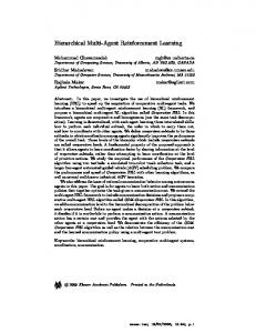
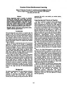
different shape and size) around than axis perpendicular to the hand palm. The objects were anchored to the world as in the case of bottle caps to be unscrewed. Each version of the model was trained for 5000 trials, each time with a different object. At the end of every trial, each lasting 300 simulation cycles, the rotation angle of the object was normalized and used as reward signal (see Sect. C). Notice that the task was rather challenging for at least three reasons. First, learning was based exclusively on the rare scalar value of reinforcement. Second, different shapes and size of the objects required different movements. Third, the rotation of the object required well coordinated dynamical movements involving the controlled joints of the fingers. B. Overview of the system architecture The overall system architecture is shown in Fig. 1. The key elements of such architecture are: three neural “experts”; one neural selector; three CPGs having a different degree of complexity (one for each expert); Proportional Derivative (PD) controllers; simulated hand and objects. Each expert and the selector receives as input the activation of a neural map encoding the object size and shape (in this study each version of the model is trained separately for each object, so this input, added to study the generalization properties of the system in future work, acts as a bias and is not further discussed here). At the beginning of each trial (and only then), each expert generates the parameters of the corresponding CPG, and the selector generates the “weights” used to “gate” the commands decided by the experts' CPGs (gating is obtained through a weighted average, see below). At each step, the desired joint angles of the expert CPGs are weighted with the selector weights to produce one desired angle for each joint. The resulting desired joint angles are sent to Proportional Derivative (PD) controllers to generate, on the basis of the current angles, the joint torques of the robotic simulated hand engaged in rotating the object. The experts and selector are in charge of discovering by trial-and-error the parameters to send to the three CPGs so that the hand maximizes the rotation of the object. Learning is supported by a “critic” component computing the TD-error (the learning of the system is based on the actor-critic reinforcement learning algorithms) and is performed, at the end of each trial, on the basis of a reinforcement signal proportional to the rotation of the object. In the follows all these components and processes are described in detail. C. Architecture, functioning and learning of the neural network component The core of the model is based on a hierarchical actor-critic reinforcement-learning component (Fig. 2) formed by three experts, three CPGs associated to the experts, a selector, and a critic (the gating used here is inspired by the seminal model [30]; see [31] for a hierarchical actor-critic reinforcementlearning model that does not use CPGs). 1) Actor experts functioning The three experts get as input the object size and shape and return as output the parameters of the three CPGs (amplitude, phase, frequency, and offsets, see Sect. C) They are described below:
Fig. 1 The architecture of the hierarchical version of the model. The components of the model are: actor-critic reinforcement learning experts and selector, CPGs, PD Controllers, and simulated hand and object. Arrows represent information flows happening at each steps whereas dashed arrows represent information flows happening at the beginning of each trial.
First expert: 12 output units encoding the parameters of the CPG-C (i.e. “complex CPG”) illustrated in Fig. 3.a. Second expert: 5 output units encoding the parameters of the CPG-M (i.e. “medium complexity CPG”) illustrated in Fig. 3.b. Third expert: 2 output units encoding the parameters of the CPG-S (i.e. “simple CPG”) illustrated in Fig. 3.c. Formally, the output unit yj of the experts (all encoded in a single vector) receive the signals from the input units xi of the input array (encoded in a vector) via connections weights wji and form an activation potential PAj:
PAj = ∑ (w ji xi )
(1)
i
and an activation based on a sigmoidal function:
y j = 1 (1 + e − PAJ )
(2)
To foster exploration, a noise is added to yj : N j
y = yj + N
(3)
where N is a random number. During each training session, N is drawn from a uniform distribution with a range gradually moving from [-0.5, 0.5] to [-0.05, 0.05] from the beginning to 60% of the training (afterwards the range is kept constant). 2) Selector functioning The selector receives the same input of the experts and has three output sigmoidal units, each encoding the weight to assign to one of the three CPGs. The desired hand joint angles are computed on the basis of the selector output and the output of the three CPGs associated to the experts: out = s1OCPG −C + s 2 OCPG − M + s3OCPG − S (4)
s j=
y sj
∑ i
y si
(5)
where out is the vector of the desired joint angles, OCPG-C, OCPG-M, and OCPG-S are the desired joint angles of the CPGs, ysj is the activation of the selector output unit j, and sj is the
Fig. 2 The architecture of the reinforcement learning component and the CPGs associated with the experts of the component
normalized selector output unit j. out is remapped onto the range of movement of the controlled joints. 3)Critic functioning The critic receives the same input of the experts and has a linear output unit estimating the evaluation E of the currently perceived state based on the connections weights wi:
E = ∑ (wi xi )
(6)
i
4) Critic learning The critic computes the TD-error that determines whether things have gone better or worse than expected, and uses this to update the weights as follows: Δwi = η E Sxi (7) where ηE is a learning rate (set to 0.1) and S = R - E is the TD-error ("or surprise") with R equal to the reward. R is proportional to the object rotation in each trial, suitably scaled to have values around 1. 5) Actor network learning The weights of actor experts are updated as follows:
Δw ji = η A S ( y Nj − y j )( y j (1 − y j )) xi
(8)
where ηA is a learning rate, set to 0.1. If S > 0 the weights change leads yj to approach yjN, if S < 0 the weights change leads yj away from yjN. D. The CPGs models used in the system CPGs were used to produce rhythmic trajectories and were modeled as coupled oscillators each controlling a different joint DOF. A very stable CPG was proposed by Ijspeert [33]. A single oscillator of this CPG can be expressed as follows:
ϑ�i = 2πν i + ∑ r j wij sin(ϑ J − ϑi − φ ij ) j
(9)
⎛a ⎞ �r�i = ai ⎜ i (Ri − ri ) − r�i ⎟ ⎝4 ⎠
(10)
xi = ri (1 + cos(ϑi ))
(11)
where θi is the phase of the CPG oscillator i, ri is the amplitude, νi is the intrinsic frequency, Ri is the desired amplitude, ai is a positive constant determining how quickly ri converges to Ri, Φij is the desired phase difference (coordinated delay) between oscillator i and oscillator j of the CPG, wij is establishes the strength of the coupling of i with j. The evolution of the phase θi depends on the intrinsic frequency νi, on the coupling wij and on the phase lag Φij of the coupled oscillators. Amplitude variable ri smoothly follows Ri with a damped second order differential law. Ijspeert's CPG was modified as follows to have the possibility of regulating the centre of oscillation of each oscillator:
ϑ�i = 2πν i + ∑ r j wij sin(ϑ J − ϑi − φij )
(12)
j
⎛a ⎞ �r�i = ai ⎜ i (Ri − ri ) − r�i ⎟ ⎝4 ⎠ ⎛b ⎞ c��i = bi ⎜ i (Ci − ci ) − c�i ⎟ ⎝4 ⎠ xi = ci + ri cos(ϑi )
(13)
(14) (15)
where Ci is the desired center of oscillation of the oscillator i, and ci is the actual centre. Ci allows oscillations around any position of the joint DOF. As a result, each CPG needs three types of parameters to be controlled (Ri: desired amplitude; Ci: desired oscillation center; νi: desired oscillation frequency) and one parameter for each coupling (Φij; for simplicity in this simulations wij was 1). The CPGs used here are shown in Fig. 3. Fig. 3.a shows the complex CPG (GPG-C) having 4 oscillators: N1 generates the desired angle of the flexion/extension of the index (FEI); N2 generates the desired angle of the adduction/abduction of the index (AAI); N3 generates the desired angle of the flexion/extension of the thumb (FET); and N4 generates the desired angle of the opposition of the thumb (OT) . In this case the expert produces 12 CPG parameters: ν (used for all oscillators), R1CPG1 , R2CPG1, R3CPG1, R4CPG1, C1CPG1 ,C2CPG1, C3CPG1, C4CPG1, Φ12CPG1, Φ13CPG1, Φ34CPG1. Fig. 3.b shows the medium complexity CPG (GPG-M) having 2 oscillators: N1 generates the desired angle for both FEI and FEIT; N2 generates the desired angle for both AAI and OT. The expert of this CPG produces 5 parameters: R1CPG2 , R2CPG2 , C1CPG1 ,C2CPG2, Φ12CPG2. Fig. 3.c shows the last simple CPG (CPG-S) having only 1 oscillator, N1, that generates the desired angles for all DOFs. The expert of this CPG produces only 2 parameters: R1CPG3 , C1CPG3.
(a)
(b)
(c)
Fig. 3 The three CPGs used in the model, having different levels of complexity. (a) CPG-C with 4 oscillators (N1, N2, N3, N4). (b) CPG-M with 2 oscillators (N1, N2). (c) CPG-S with one single oscillator(N1).
E. The PDs and the simulated hand and environment
The CPGs output (desired joint angles) was sent to PDs having the following equation: T = g (q ) + K p q~ + K D q� (16) where T is the torque vector applied to the joints, g(q) is the gravity compensation, KP and KD are definite positive diagonal ~ is the difference between the desired and the matrices, q current joint angle vectors, q˙ is the angular velocity vector. The model was tested on a simulated robotic hand having the same kinematic and dynamic parameters of the iCub humanoid robot hand (www.icub.org), that is 21 links and 19 DOFs (Fig. 4a). In the simulation test 2 DOFs of the index and 2 DOFs of the thumb were controlled, while all other DOFs were kept to fixed values. The 4 DOFs controlled were (Fig. 4b): adduction/abduction (AAI) of the first index joint [-15°, 15°]; flexion/extension (FEI) of the second index joint [0°, 90°]; opposition (OT) of the first thumb joint [0°. 130°]; flexion/extension (FET) of the second thumb joint [0°, 90°]. The simulated environment was a working space containing 9 different objects with 3 different shapes (cylinder, sphere, cube) and 3 different sizes (small: 2.8 cm; medium: 3.2 cm; large: 3.6 cm; for the sphere and cylinder these are the radius size, whereas for the cube they are base diagonal size). The hand and environment were simulated using the opensource physical-engine interface software “OPAL” (Open Physics Abstraction Layer), used to interface the “NEWTON” physical engine library. The integration time step used in the physical engine was 0.01 s. III. RESULTS The various versions of the model were tested with each of the nine objects separately. Each model was trained for 5000 simulation trials, each formed by 300 steps (3 s of real time). At the beginning of each trial the hand was set at an initial posture with all fingers in a straight position. A. Effects of center of oscillations parameter (C) The performance of the hierarchical CPG (CPG-H) model using the parameters C to set the center of oscillations was compared with the performance of the same model without such parameters. The resulting performances are reported in
CPG-M CPG-C CPG-H CPG-S CPG-M Large
(a)
(b)
Fig. 4 (a) The robotic setup used to test the computational model. The angular position of the joints arm (shoulder and elbow) are kept at fixed value (shoulder=0°, elbow=0°). The object in the figure is the cylinder with 3.2 cm radius. (b) The cinematic model of the two fingers uses during manipulation task. The DOFs are represented as hinge joints.
table 1. The table shows that the model with C gets rather larger rewards. This is particularly evident for the small objects because without C the finger needs to oscillate in the whole range of amplitude indicated by the R parameter in order to touch the object, so lowering the performance of the system. Dimension Small Medium Large
Shape Sphere Cylinder Cube C No C C No C C No C 5.692 2.829 5.661 4.086 3.714 2.914 4.618 4.080 4.349 1.905 3.700 3.274 3.651 3.094 3.262 2.791 3.341 1.799
Tab.1 Comparison of rewards obtained from two simulations: “C”: reward using a CPG-H capable of regulating the centre of oscillations. “No C”: reward using a CPG-H not capable of regulating the centre of oscillation.
B .Comparison of different CPG models The performance of CPG-H was compared with the performance of the CPGs models (CPG-S, CPG-M, CPG-C). Table 2 shows the results. In Tab. 2 bold values indicate the average reward values of the models for each object. In many cases the best performance is achieved by the hierarchical model. When the objects are large, the CPG-C model overcomes the hierarchical one. With the medium cube the best performance is achieved by the CPG-M model. However, the best performance of a single run for any condition is always of the CPG-H (with the exception of the large sphere and large cylinder, where CPG-C and CPG-H have the similar performance). The table also indicate that the CPG-H has often a larger standard deviation. The reason why CPG-H has the best performance for single runs (but not always for the average) and it has often a large variance, is that it sometimes incurs in local minima. This is probably due to the larger parameter space it has to search (number of parameters: CPGH: 22; CPG-C: 12; CPG-M: 5; CPG-S: 2). Dimension
Small
Medium
Sphere 3.981±0.018 CPG-S 3.993 3.799±0.212 CPG-M 3.948 4.508±1.207 CPG-C 5.361 5.686±0.063 CPG-H 5.773 3.099±0.372 CPG-S 3.362
Shape Cylinder 3.644±0.009 3.651 4.903±0.073 4.995 4.351±0.028 4.371 5.421±0.284 5.668 3.352±0.005 3.355
Cube 3.271±0.517 3.637 3.505±0.032 3.527 3.563±0.159 3.837 4.974±0.885 5.789 3.648±0.022 3.663
CPG-C CPG-H
3.559±0.088 3.621 4.768±0.385 5.041 5.158 ± 0.441 5.528 2.445±0.005 2.449 3.680±0.330 3.914 4.085±0.033 4.108 3.502±0.319 3.869
3.975±0.085 4.036 4.103±0.297 4.313 4.429±0.074 4.528 3.059±0.006 3.063 3.232±0.008 3.238 3.644±0.215 3.796 3.530±0.223 3.771
4.781±0.035 4.806 4.017±0.071 4.4067 4.555±0.982 5.537 2.747±0.079 2.802 3.018±0.031 3.039 3.514±0.009 3.521 3.318±0.186 3.529
Tab.2 Comparison of average rewards and standard deviation for different CPG models with different objects. Each cell indicates the average value and standard deviation of the rewards obtained with four different simulations sequences with the same model. The bold font indicates the best reward value between all proposed CPG models, for every object used. Values in Italics indicate the performance of the best runs of each model.
Tab. 2 also shows that the performance is different for the various shapes and dimensions of the object (see also the reward plots of Fig. 5). In particular, data indicate specific regularities that might be tested in experiments with real infants. It can be observed that the performance increases with the decrease of the object dimension, probably because the fingers have to cover a smaller distance to achieve a certain rotation of the objects. The systems achieve the best performance with the spheres, as the systems avoid getting stuck on edges, and achieve the worst performance with the cubes, as the distance that the fingers have to cover to touch them varies continuously. Figure 5 shows the performance obtained during the simulations with different objects and different models. Each figure contains five curves. Four are related to the models using the single CPGs (CPG-S, CPG-M, CPG-C) or to the hierarchical model (CPG-H Avg): each one is the average of four runs; one is related to the best run with the CPG-H (CPGH Max). The most striking result is the fact that the CPG-H is always quite faster to learn than the single-CPG models. This notwithstanding it has many more parameters than them. The reason of this might be that the model can use the CPG that has developed good parameters so far, or the fact that it is more robust to noise (the system can avoid using a CPG whose parameters have deteriorated due to noise). However, further investigations are needed to find the exact cause. It is also interesting to note that in one case (small sphere) the CPG-H succeeds to use both fingers whereas the other models fail to do so. This results in a remarkable higher performance of the hierarchical model. The reason of this is that when the system learns to use two fingers it also learns to alternate them so to impress more rotation to the objects. The fact that in this case the CPG-H succeeds to use two fingers might be the sign that it manages to find and to exploit the advantages of using two fingers in coordination, whereas the other models do not (another sign of the higher facility to learn of the system). The second result, anticipated by discussing Tab. 2, is that the CPG-H always achieves the best final performance with a single run (with the exception of the large sphere and cylinder for which it has a performance similar to the CPG-C).
Small Sphere
2
1
1
1000
1500
2000
2500 Trials
3000
3500
4000
4500
5000
1
1
1500
2000
3000
3500
4000
4500
2
1
1
1000
1500
2000
2500 Trials
4500
5000
0 0
3000
3500
4000
4500
5000
500
1000
1500
2000
4
2500 Trials
3000
3500
4000
4500
5000
Large Cylinder
6
1000
1500
2000
2500 Trials
3000
3500
4000
4500
CPG-S CPG-M CPG-C CPG-H Avg CPG-H Max
3
0 0
5000
Medium Cube
6 5
Reward
4
3
2
500
4000
CPG-S CPG-M CPG-C CPG-H Avg CPG-H Max
4
3
0 0
3500
1
500
5
Reward
4
3000
5
6
CPG-S CPG-M CPG-C CPG-H Avg CPG-H Max
5
2500 Trials
2
0 0
5000
Small Cube
6
Reward
2500 Trials
2000
3 2
1000
1500
Reward
Reward
Reward
4
2
500
1000
CPG-S CPG-M CPG-C CPG-H Avg CPG-H Max
5
3
0 0
1
500
6
CPG-S CPG-M CPG-C CPG-H Avg CPG-H Max
4
3
Medium Cylinder
Small Cylinder
CPG-S CPG-M CPG-C CPG-H Avg CPG-H Max
2
0 0
6 5
4
3
2
500
5
Reward
4
3
0 0
CPG-S CPG-M CPG-C CPG-H Avg CPG-H Max
5
Reward
Reward
4
6
6
CPG-S CPG-M CPG-C CPG-H Mean CPG-H Max
5
Large Sphere
Medium Sphere
6
500
1000
1500
2000
2500 Trials
3000
3500
4000
4500
5000
3000
3500
4000
4500
5000
Large Cube
CPG-S CPG-M CPG-C CPG-H Avg CPG-H Max
3 2 1
0 0
500
1000
1500
2000
2500 Trials
3000
3500
4000
4500
5000
0 0
500
1000
1500
2000
2500 Trials
Fig. 5 The reward (y-axis) obtained in 5000 learning trials (x-axis) by the different models engaged in the manipulation of the nine objects. The curves CPG-S, GPG-M, CPG-C, and CPG-H Avg report the average for four repetitions of the learning simulations. The curve GPG-H Max reports the best run for the CPG-H.
Index: Flexion-Extension
Joint Trajectories
1
CPG-C CPG-M CPG-S
0.5
0 0
50
100
Joint Trajectories
1
150 Cycles
200
250
300 CPG-H: desired CPG-H: real
0.5
0 0
50
100
150 Cycles
200
250
300
Index: Adduction-Abduction Joint Trajectories
1
CPG-C CPG-M CPG-S
0.5
0 0
50
100
150 Cycles
200
250
Joint Trajectories
1
300 CPG-H: desired CPG-H: real
0.5
0 0
50
100
150 Cycles
200
250
300
Thumb: Flexion-Extension Joint Trajectories
1
CPG-C CPG-M CPG-S
0.5
0 0
50
100
Joint Trajectories
1
150 Cycles
200
250
300 CPG-H:desired CPG-H:real
0.5
0 0
50
100
150 Cycles
200
250
300
Thumb: Opposition Joint Trajectories
1
CPG-C CPG-M CPG-S
0.5
0 0
50
100
150 Cycles
200
250
Joint Trajectories
1
300 CPG-H: desired CPG-H: real
0.5
0 0
50
100
150 Cycles
200
250
300
Fig. 6 Examples of trajectories of the hand controlled joints measured at the end of training with the small sphere. Within each couple of graphs, the upper graph shows the desired trajectory a joint generated by the three single-CPG models (CPG-C, CPG-M, CPG-S), whereas the lower graph shows the desired and real trajectories generated by the CPG-H model. The four couples of graphs refer to the four controlled joint DOFs: FEI, AAI, FET, and OT.
However, in some cases (medium sphere, small cylinder, and small and medium cube) such performance is higher than its own average, indicating the fact that it sometimes cannot escape local minima. In the follows are analyzed the functioning of the models more in detail. Fig. 6 reports an example of desired joint trajectories generated by the different models (CPG-S, CPGM, CPG-C, CPG-H) during a manipulation of a small sphere for 3 s. In the case of the CPG-H, the figure also reports the trajectory actually followed by the joints. Various interesting facts are apparent from the figure. First, all models have managed to find a similar oscillation frequency, probably the good/optimal one. Second, the models, for example the CPGH, can exploit the possibility of regulating the oscillation centers to have a good contact with the objects (see for example how in the graph of the CPG-H FET the desired joint angle leads the finger to hit the object and press it so to have a suitable grip on it). Third, recall from above that the higher flexibility of the CPG-H allows it to discover the use of both fingers whereas the other models fail to use the thumb: this is shown by the fact that the desired centers of oscillation of FET of the single-CPG models are below 0.5 (hence far from the object), whereas that of the CPG-H is above 0.5. Fourth, Fig. 5 showed that by using both fingers the CPG-H could have a higher performance: Fig. 6 indeed shows that CPG-H moves AAI and OT with an opposite phase so as to alternate the fingers contact with the object and keep the object continuously rotating. Fig. 7 reports the trajectories in the 3D space of the thumb and index tips during the same test of Fig. 6, for the CPG-C and CPG-H models. The figure shows how the hierarchical model manages to bring both fingers in contact of the object by also maintaining a suitable distance from it when regarding the contact. The CPG-C, instead, fails to learn to use the thumb and so brings it far away from the object to avoid interfering with its rotation.
INDEX
Selectors
Z
14 12 10
0.5
0.5
0.4
0.4 Selectors
THUMB
16
0.3 0.2
8 8 6 4 2
(a)
0
18
16
14
20
Y
22
24
0.2 CPG-C CPG-M CPG-S
0.1 0 0
X
0.3
1000
2000 3000 Trials
4000
5000
CPG-C CPG-M CPG-S
0.1 0 0
1000
(a)
2000 3000 Trials
4000
5000
(b)
INDEX
Fig. 8 Activations of the selector output units (gates) that the CPG-H develops in two training sessions using the small sphere.
THUMB
16
Z
14 12 10 8 8 6
(b)
4 2 0
16
Y
20
18
22
24
X
Fig. 7 Trajectories followed by the finger tips during the manipulation of a small sphere (the gray circle marks its position). (a) Trajectories generated by the CPG-H model. (b) Trajectories generated by the CPG-C model.
Fig. 8 shows a last important result: the CPG-H is capable of using many CPGs by suitably mixing them. Indeed, the two graphs show that the CPG-H evolves a mixed use of the available CPGs and after about 2000 learning trials maintains such mixture in a stable fashion. Note that in both the learning runs the reward obtained was approximately the same. This demonstrates that the same task can be solved with different mixed combinations of the CPGs.
Future work will investigate how to make the hierarchical model more robust, in order to avoid occasionally incurring in local minima. Notwithstanding this current limit, the model seems a promising tool to investigate the emergence of rhythmic manipulation skills in primates due to its bioinspired architecture and the behaviour exhibited so far. This study might be an important complement of the studies on the development of discrete hand movements [32]. ACKNOWLEDGMENT This research was supported by the EU funded Projects ‘IM-CLeVeR – Intrinsically Motivated Cumulative Learning Versatile Robots’, contract no. FP7-IP -231722 and ‘ROSSI – Emergence of communication in RObots through Sensorimotor and Social Interaction’, contract no. FP7STREP-216125 and by MIUR project 'OPENHAND - OPEN neuro-prothesic HAND platform for clinical trials'.
IV. CONCLUSIONS This research has proposed a hierarchical reinforcement learning model that can be used to study the development of rhythmic manipulation skills in infants. The model resorts to a bio-inspired hierarchical reinforcement-learning architecture. It is grounded on the key idea that rhythmic manipulation movements are generated on the basis of central pattern generators (e.g. located in the spinal cord), and that the parameters of these can be found by trial-and-error mechanisms. The system validation tests show that the model might indeed be a valuable tool to study the development of rhythmic manipulation skills. For example, they show how manipulation skills might develop in various ways, yielding different performances, depending on the different challenges posed by the different objects (alternatively, the results might predict different ages of learning of the manipulation of the different objects considered here). The hierarchical version of the model was also able to learn rather faster than the simple versions, notwithstanding its higher number of parameters. Notably, it did so by suitably finding the mixture of CPGs with different complexity to be used in different tasks. This can be considered a prediction in the case it becomes possible to empirically investigate the contextual use of many CPGs with different complexity in infants and non-human primates.
REFERENCES [1] [2] [3]
[4] [5] [6] [7]
[8] [9]
C. G. Bernhard, E. Bohm, & I. Peterson, "Investigations on the organization of the corticospinal system in monkeys (Macaca mulatta)". Acta Physiological Scandinavica, vol. 29(Suppl. 106), 1953, pp 79–105. R. Porter, R. Lemon, Corticospinal function and voluntary movement. Oxford: Clarendon Press, 1993. P. S. Wallace, I. Q. Whishaw, "Independent digit movements and precision grip patterns in 1–5-month-old human infants: hand-babbling, including vacuous then self-directed hand and digit movements, precedes targeted reaching independent digit movement." Neuropsychologia, vol. 41, 2003 pp 1912–1918. C. von Hofsten, "Eye-hand coordination in newborns." Developmental Psycology, vol. 18, 1982, pp. 450–461. J. Piaget, "The origins of Intelligence in Children", New York: International Universities Press, 1952. D. Bullock, S. Grossberg, F. Guenther, "A self-organizing neural model of motor equivalent reaching and tool use by a multijoint arm. Journal of Cognitive Neuroscience, vol. 5, 1993, pp. 408-435 D. Caligiore, T. Ferrauto, D. Parisi, N. Accornero, M. Capozza, G. Baldassarre, "Using motor babbling and Hebb rules for modeling the development of reaching with obstacles and grasping" In R. Dillmann, C. Maloney, G. Sandini, T. Asfour, G.Cheng, G. Metta, A. Ude, E1-8. International Conference on Cognitive Systems. Berlin, Springer Verlag. 2008 E. Thelen "Rhythmical stereorypies in normal human infants" . Animal Behaviour vol. 27, 1979, pp. 699-715. S. Schaal, P. Mohajerian, A. Ijspeert. Dynamics systems vs. optimal control - A unifying view. Progress in Brain Research, Neuroscience, vol. 165, 2007, pp. 425-445.
[10] S.A. Fontenelle, B.A. Kahrs, S. Ashely Neal, A. Taylor Newton, J.J. Lockman, "Infant manual exploration of composite substrates". Journal of Experimental Child Psychology, vol. 98, 2007, pp 153-167. [11] W. K. Geerts, C. Einspieler, J. Dibiasi, B. Garzarolli, A. F. Bos, "Development of manipulative hand movements during the second year of life" . Early Human Development, vol. 75, 2003, pp 91-103. [12] A. Henderson, C. Pehoski, "Hand Function in the Child: Foundations for Remediation" Mosby Elsevier, 2006. [13] J. J. Gibson, The ecological approach to visual perception. Boston: Houghton, 1979. [14] E. J. Gibson, A.D. Pick, An ecological approach to perceptual learning and development. New York: Oxford University Press, 2000. [15] R.S. Sutton and A.G.Barto, Reinforcement learning: An Introduction. Cambridge MA, USA: The MIT Press, 1998. [16] J. C. Houk, J. Davis, D. Beiser, Models of Information Processing in the Basal Ganglia. The MIT Press, Cambridge, MA, 1995. [17] J. Peters, S. Vijayakumar, S. Schaal, S. "Natural actor-critic Machine Learning", ECML2005, 2005, pp. 280-291 [18] S. Schaal, J. Peters, J. Nakanishi, A. Ijspeert, "Learning movement primitives" Robotics Research, 2005, pp. 561-572. [19] J. Peters, S. Schaal, "Reinforcement learning of motor skills with policy gradients". Neural Networks, vol. 21, 2008, pp. 682-697. [20] A. J. Ijspeert, A. Crespi, D. Ryczko, J.M. Cabelguen "From Swimming to Walking with a Salamander Robot Driven by a Spinal Cord Model", Supporting Online Material Science 315, 2007, 1416. [21] A.J. Ijspeert "Central pattern generators for locomotion control in animals and robots: a review", Neural Networks vol.21, 2008, pp. 642653. [22] G. N. Orlovsky, T. G. Deliagina, and S. Grillner, "Neuronal control of locomotion: from mollusc to man", Oxford University Press, 1999. [23] H. Taguchi, K. Hase, and T. Maeno "Analysis of the motion pattern and the learning mechanism for manipulation objects by human fingers" (in
[24] [25]
[26]
[27] [28] [29] [30] [31]
[32]
japanese). Trans. of the Japan Society of Mechanical Engineers, vol. 68, 2002, pp. 1647–1654. H. Heuer, R. Schulna, A. Luttmann, "The effects of muscle fatigue on rapid finger oscillations", Exp Brain Res, vol 147, 2002, pp. 124-134. Y. Kurita, J. Ueda, Y. Matsumoto, T. Ogasawara "CPG-Based Manipulation: Generation of Rhytmic Finger Gaits from Human Observation", Proceedings of the 2004 IEEE International Conference on Robotics & Automation New Orleans, 2004 . Y. Kurita, K. Nagata, J. Ueda, Y. Matsumoto T. Ogasawara "CPGBased Manipulation: Adaptive Switchings of Grasping Fingers by Joint Angle Feedback", Proceedings of the 2005 IEEE International Conference on Robotics and Automation, 2005 . F.A. Middleton, P.L. Strick, "Basal ganglia and cerebellar loops: motor and cognitive circuits" Brain Research Reviews, vol. 31, 200, pp. 236250. G. Luppino, G. Rizzolatti, G. "The Organization of the Frontal MotoCortex", News in physiological sciences, vol. 15, 2000, pp. 219224. G. Baldassarre" A modular neural-network model of the basal ganglia’s role in learning and selecting motor behaviours", Journal of Cognitive Systems Research, vol. 3, 2002, pp. 5–13. R.A. Jacobs, M.I. Jordan, S.J. Nowlan, G.E. Hinton, "Adaptive Mixtures of Local Experts", Neural Computation, vol. 3, 1991, pp. 79-8. D. Caligiore, M. Mirolli, D. Parisi, G. Baldassarre, "A Bioinspired Hierarchical Reinforcement Learning Architecture for Modeling Learning of Multiple Skills with Continuous States and Actions" Proceedings of the Tenth International Conference on Epigenetic Robotics (EpiRob2010). In J. Birger, S. Erol, C. Balkenius (Eds) Lund University Cognitive Studies, 149, 2010, pp. 5-7. G. Butterworth, E. Verweij, B. Hopkins,"The development of prehension in infants: Halverson revisited. British Journal of Developmental Psychology, vol. 15, 1997, pp. 223–236.