MITSUBISHI ELECTRIC RESEARCH LABORATORIES http://www.merl.com
High-Dimensional Modulation for Mode-Division Multiplexing
Arik, S.O.; Millar, D.S.; Koike-Akino, T.; Kojima, K.; Parsons, K.
TR2014-011
March 2014
Abstract We explore high-dimensional modulation for mode-division multiplexed optical fiber communication systems, focusing on optimized 24-D modulation formats in six-mode fiber transmission. Compared with conventional formats, our simulations demonstrate up to 8.7 dB span loss budget improvement for 6 b/s/Hz intra-channel spectral efficiency. Optical Fiber Communication Conference and Exposition (OFC)
This work may not be copied or reproduced in whole or in part for any commercial purpose. Permission to copy in whole or in part without payment of fee is granted for nonprofit educational and research purposes provided that all such whole or partial copies include the following: a notice that such copying is by permission of Mitsubishi Electric Research Laboratories, Inc.; an acknowledgment of the authors and individual contributions to the work; and all applicable portions of the copyright notice. Copying, reproduction, or republishing for any other purpose shall require a license with payment of fee to Mitsubishi Electric Research Laboratories, Inc. All rights reserved. c Mitsubishi Electric Research Laboratories, Inc., 2014 Copyright 201 Broadway, Cambridge, Massachusetts 02139
MERLCoverPageSide2
High-Dimensional Modulation for Mode-Division Multiplexing ¨ Arık1,2 , David S. Millar1 , Toshiaki Koike-Akino1 , Sercan O. Keisuke Kojima1 and Kieran Parsons1 2
1 Mitsubishi Electric Research Laboratories, 201 Broadway, Cambridge, MA 02139, USA E. L. Ginzton Laboratory, Department of Electrical Engineering, Stanford University, Stanford, CA 94305, USA
[email protected]
Abstract: We explore high-dimensional modulation for mode-division multiplexed optical fiber communication systems, focusing on optimized 24-D modulation formats in six-mode fiber transmission. Compared with conventional formats, our simulations demonstrate up to 8.7 dB span loss budget improvement for 6 b/s/Hz intra-channel spectral efficiency. OCIS codes: (060.2330) Fiber optics communications, (060.4080) Modulation, (060.4230) Multiplexing.
1. Introduction As global data traffic increases exponentially [1], higher capacity long-haul systems are essential to sustain the growth of information technologies. Mode-division multiplexing (MDM) in multi-mode fibers (MMF) provide an intriguing option since the data paths in mutually orthogonal modes can proportionally increase the degrees of freedom for transmission [2]. Beyond the integration of the waveguide medium, MDM also promises possibilities for electronic and photonic integration of transmission components [3]. Commonly used 2-D modulation formats map a 2-D symbol constellation to the in-phase and quadrature (I/Q) signal components. As single-mode fiber (SMF) has two transverse polarization modes which support a four-dimensional carrier, optimized 4-D modulation formats have been of interest for dual polarization (DP) SMF transmission [4], [5]. Further considerable performance improvements were demonstrated for optimized modulations with dimensionality greater than four by constellation mapping to the available four dimensions in a serialized form [6, 7]. A similar idea can also be generalized to MDM where the number of available carrier dimensions scales with the number of propagating modes, as considered in the context of coded modulation [8]. In this paper, we investigate implementation possibilities and performance characteristics of high-dimensional modulation for MDM, specifically focusing on two optimized 24-D modulation formats in six-mode MMF transmission.
…
b12
To decoder
…
b1 b2 b3
Parallel-to-serial
…D16, D15
D24
D1 D2 D3
Demodulator
…D14, D13
Mode demapper
6x6 MIMO eq.
CD eq.
ADC
…D12, D11
4-D demapper
CD eq.
ADC
LPF LPF
Mode DEMUX
…D8, D7 …D10, D9
4-D demapper
…D16, D15
DP downconv.
I/Q Mod. I/Q Mod. I/Q Mod. I/Q Mod.
LPF
…D14, D13
DAC
4-D mapper
…D12, D11
…D6, D5
…
b12
Mode mapper
…
…D10, D9
…D2, D1 …D4, D3
…
Modulator
D1 D2 D3
…
From encoder
…
…
Serial-to-parallel
…D8, D7 b1 b2 b3
(b)
LPF
…D6, D5
DAC
4-D mapper
…D2, D1 …D4, D3
Mode MUX
(a)
DP downconv.
2. Fiber modes as modulation dimensions
…D20, D19 …D22, D21 …D24, D23
4-D demapper
CD eq.
ADC
…D18, D17 LPF
I/Q Mod. I/Q Mod.
…D24, D23
LPF
…D22, D21
DAC
4-D mapper
…D20, D19
DP downconv.
D24
…D18, D17
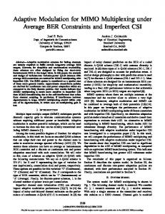
Fig. 1: (a) Transmitter and (b) receiver architecture for a 6-mode system employing 24-D modulation (Single wavelength is shown)
An MMF supporting N spatial modes (total 2N modes), supports propagation of the 4N-dimensional carrier at a given instant that can render modulation with dimensionality 4N. Furthermore, considering allocation of constellation dimensions to available 4N dimensions in a temporally serialized form [7], a high-dimensional modulation format
with dimensionality of multiples of 4N can be employed (see Fig. 1(a)). Since desired optimized modulation formats designs are available for some specific dimensionalities (such as 24) [7], this technique becomes particularly important. Two main stages of a transmitter (see Fig. 1(a)) are: (i) mapping of encoded information bits to multi-dimensional constellation points and (ii) mapping of the constellation points to the available parallel data paths. Implementation of (i) is look-up table based for sphere-cut modulations and binary linear algebra based for binary block coded modulations [7]. Required implementation memory (ii) for depends on the the ratio of modulation dimensionality and number of I/Q dimensions (which is 2 for N = 3 and 24-D modulation example). The receiver (see Fig. 1(b)) is implemented in an analogous structure to the transmitter. After detection and impairment compensation subsystems, the two main stages are: (i) demapping of the parallel data paths to the multi-dimensional signal points and (ii) demapping of the received multi-dimensional signal points to information bits to be sent to the outer decoder. 3. MDM transmission simulation We consider two optimized 24-D formats with 0.5 bits/symbol/dimension spectral efficiency (the same as DP-BPSK): (1) Extended Golay coded modulation: Based on extended Golay code that has block length of 24 and minimum Hamming distance of 8 [7], and (2) 12b-24D sphere-cut modulation: obtained by spherical cutting of 24-D Leech lattice [7]. Both 24-D formats yield ∼ 6 dB asymptotic power efficiency gain with respect to DP-BPSK [7]. As comparison cases, we consider DP-BPSK and DP-QPSK, based on independent modulation of spatial modes. We assume 3 × 112 Gb/s transmission in a 4000 km long six-mode MMF. At the transmitter, DP modulators are driven by ideal rectangular signals of the symbol value in corresponding dimension, filtered by a 5th order Bessel filter with −3 dB cut-off frequency of 0.7 times the symbol rate. Modulated signals are multiplexed in orthogonal polarizations, then in spatial modes and finally in wavelength by ideal multiplexers. 5 wavelength channels with 50 GHz spacings for DP-QPSK and 100 GHz spacings for the other three modulation formats are simulated for interchannel nonlinearities. The MMF link consists of 50 spans (each of length 80 km) separated by multi-mode erbiumdoped fiber amplifiers with 5 dB noise figure and no mode dependent gain. To quantify the transmission performance in terms of span loss budget, variable optical attenuators are considered [5]. We assume MMF propagation in the regime of ideal strong mode coupling so that it can be modeled based on multi-mode Manakov equation [9] [10]: ′′
′ ∂E ∂E α β ∂ 2E + E+β +i = i · γ · κ · |E|2 · E, ∂z 2 ∂t 2 ∂t 2
(1) ′
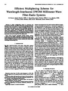
where E is the 6 × 1 baseband electric field envelope vector, α is attenuation coefficient, β is average inverse group ′′ velocity, β is average chromatic dispersion coefficient, γ is nonlinear coefficient and κ is a dimensionless constant ′′ depending on nonlinear coupling coefficients [2]. Inspired by [11], we choose α = 0.2 dB/km, β = 20 ps/nm/km and γ · κ = 0.663 (km·W)−1 . At the receiver, signals are demultiplexed by wavelength and spatial mode, and ideal DP homodyne coherent detection is applied for each spatial mode. Limited analogue receiver bandwidth is modeled as a 5th order Bessel low-pass filter with −3 dB cut-off frequency of 0.7 times the symbol rate, applied before the signal is sampled at 2 times the symbol rate. After quantization, the following signal processing was applied: normalization, frequency domain chromatic dispersion equalization, and 6 × 6 time-domain equalization based on data-aided least mean squares algorithm [12]. After impairment compensation subsystems, high-dimensional demodulator first forms the multi-dimensional symbols as in Fig. 1(b), and applies maximum-likelihood symbol estimation. In this work, we do not simulate the actual outer FEC decoder performance but rather assume target BER values of 10−2 and 10−3 to represent threshold values for FEC codes. 4. Results and discussions We first perform Monte-Carlo simulations over a purely additive white Gaussian noise (AWGN) channel, and plot BER performances in Fig. 2(a). Fig. 2(b) shows the constellations without ASE for the optimum launch powers at a BER of 10−3 . Extended Golay coded modulation yields around 1.9 and 3 dB gain, while 12b-24D sphere-cut modulation yields around 1.5 and 2.9 dB gain with respect to DP-BPSK/DP-QPSK for BER of 10−2 and 10−3 respectively. Transmission performances are then simulated in terms of span loss budget at a target BER of 10−2 (Fig. 2(c)) and 10−3 (Fig. 2(d)). It is noted that in the low launch power regime where noise and dispersions are dominant, performance is as expected from the AWGN results shown in Fig. 2(a). In the nonlinear regime, we observe several differences. DP-QPSK has the worst performance which we attribute to its relatively low noise tolerance and lower symbol rate as the reduction in effective dispersion leads to increased nonlinear effects. DP-BPSK has a much improved nonlinear tolerance compared with DP-QPSK, due to its increased phase margin and higher symbol rate. This results in an increase of 4.3 and 4.5 dB in span loss budget compared with DP-QPSK for BERs of 10−2 and 10−3 . 12b-24D sphere-cut modulation has
(b)
DP-QPSK/DP-BPSK
Ext. Golay coded
(a)
12b-24D DP-BPSK Sphere-cut
Ext. Golay coded 12b-24D Sphere-cut
-2
BER
10
-3
0
(c)
2
4 Eb / N0 (dB)
6
DP-QPSK
10
8
32
Span loss budget (dB)
Span loss budget (dB)
12b-24D Sphere-cut
26 24 22 20 18
DP-BPSK Ext. Golay coded
28
12b-24D Sphere-cut
26 24 22 20 18 16
16 -7
DP-QPSK
30
DP-BPSK Ext. Golay coded
28
32
(d)
DP-QPSK
30
-5
-3
-1
1
3
Launch power (dBm)
5
7
-7
-5
-3
-1
1
3
5
7
Launch power (dBm)
Fig. 2: (a) Additive white Gaussian noise channel performances (Eb : Energy per bit, N0 : Unilateral noise power spectral density) (b) Recovered constellations at the optimum launch power in (c) in the absence of amplified spontaneous emission noise, showing the effects of nonlinear distortion. Span loss budget vs launch power per spatial mode for optical signal-to-noise ratio corresponding to BER of (c) 10−2 and (d) 10−3 .
considerable performance degradation in the nonlinear region, which we attribute to its higher peak-to-average power ratio as is evident in the constellations plotted in Fig. 2(b). For this format we see an increase of 3 dB and 5 dB in span loss budget compared with DP-QPSK for BERs of 10−2 and 10−3 , and also 0.5 dB increase compared with DP-BPSK for BER of 10−3 . Extended Golay coded modulation has the best performance due to its low peak-to-average power ratio, high noise sensitivity and high symbol rate. In this case, we see an improvement in span loss budget of 6.7 dB and 8.7 dB compared with DP-QPSK (and 2.4 dB and 4.2 dB compared with DP-BPSK) at BERs of 10−2 and 10−3 respectively. 5. Conclusions We investigated MDM transmission in six-mode MMF using optimized 24-D modulation formats obtained by spherical lattice cutting and binary block coding. We demonstrated up to 8.7 dB and 4.2 dB span loss budget improvements with respect to DP-QPSK and DP-BPSK. Our results demonstrate the premise of block-coded high-dimensional formats for MDM long-haul systems that can comprise additional lossy components and increased nonlinearities. References 1. R. Tkach, Bell Labs Tech. J., 14, pp. 39 (2010). 2. R. J. Essimabre, R. W. Tkach, and R. Ryf, “Fiber nonlinearity and capacity: single-mode and multimode fibers”, in Optical Fiber Telecommunications VI, I. P. Kaminow, T. Li and A. E. Willner, Eds. (2013) . 3. D. J. Richardson, J. M. Fini, and L. E. Nelson, Nature Photonics 7, 354-362 (2013). 4. E. Agrell, and M. Karlsson, J. Lightw. Technol.27, 5115-5126 (2009). 5. P. Poggiolini et al., Opt. Expr. 18, 11360-11371 (2010). 6. T. Koike-Akino et al., Proc. ECOC 2013, Tu.3.C.3 (2013). 7. D. S. Millar et al., Proc. SPPCOM 2013, SPM3D.6 (2013). 8. I. Djordjevic, J. Lightw. Technol. 30, 3888-3901 (2012). 9. S. Mumtaz, R. J. Essiambre, and G. P. Agrawal, J. Lightw. Technol. 31, 398-406 (2013). 10. A. Mecozzi, C. Antonelli, and M. Shtaif, arXiv:1203.6275 (2012). 11. D. W. Peckham et al. “Few-mode fiber technology for spatial multiplexing”, in Optical Fiber Telecommunications VI, I. P. Kaminow, T. Li and A. E. Willner, Eds. (2013). 12. N. Bai, et al., Opt. Expr. 20, 2668-2680 (2012).