Dynamic range reduction algorithm for display device. ⢠Method Based on retinex theory of vision. â Prevention of artifact. » Halo and clipping of highlight.
High Dynamic Range Image Display With Halo and Clipping Prevention IEEE Transactions on Image Processing, Vol. 20, No. 5, 2011 Gabriele Guarnieri, Stefano Marsi, and Giovanni Ramponi
Presented by Bong Seok Choi
School of Electrical Engineering and Computer Science Kyungpook National Univ.
Abstract Aim
in proposed method
– Dynamic range reduction algorithm for display device • Method Based on retinex theory of vision – Prevention of artifact » Halo and clipping of highlight
• Reducing computational cost • Applying limitedness number of parameter
2 / 36
Introduction Related
work
– Intensity of natural light • Span over ten orders of magnitude
– Dynamic range • Ratio between highest and lowest luminance level
– Characteristics of human vision • Perceiving brightness of each point
3 / 36
Proposed
method
– Expressing HDR image on display device • Reducing dynamic range
– New method of dynamic range reduction algorithm • Base on retinex theory – Attempt to separate illumination and reflectance of image
• Filter for estimation of illumination component – Using edge-preserving filter » Prevention to halo and clipping of highlight
4 / 36
Advantage
of proposed method
– Dividing threefold • Absence of halo and clipping artifact – Expressing great naturalness image
• Reducing computational cost • Each parameter easy to tune individually – Applying Low number of parameter
5 / 36
Retinex Theory of Vision Description
of intensity of light
– Product of Illumination and reflectance • Illumination depend on light source • Reflectance depend on surface of object
L x, y
Retinex
I x, y R x, y
(1)
theory
– Perceiving image by illumination and reflectance • Retinex – Contraction of retina and cortex
6 / 36
– Mondrian experiment • Edwin Land and John McCann – Experimental condition
» Using 100 sheet of different color paper to test target » Adjustment of intensity and – Determination of Visual sensation by reflectance of object » Influencing minimum by illumination – Mistake of experiment » Using uniform illumination » Perceiving color of object change according to illumination – Validity of retinex model » Experienced in process of vision » Sufficiently accurate way to human vision mechanisms 7 / 36
Dynamic
range reduction algorithm
– Based on retinex theory • Attempt to separation of reflectance and illumination component of image • Retinex processing on Color image – Applying each color channel
Fig. 2. Block diagram of a general Retinex-based algorithm for gray scale images.
8 / 36
– Reducing dynamic range • Illumination mapping – Using nonlinear function
» Introducing Land and McCann – Using power law » Introducing Kimmel
• Processing reflectance – Emphasis of detail – Reducing noise – Clipping outlier
• Multiplication two component
9 / 36
Separation
of illumination and reflectance
– Applying high-pass filter • Reducing dynamic range of low-frequency component – Illumination smooth and reflectance contain high-pass filter
– Provenzi et al. • Proving illumination computed local maximum of luminance
10 / 36
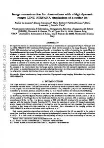
Fig. 3. Reflectance of the “Memorial” test image (courtesy: Paul Debevec), estimated with the four kind of filters described in section II. (a)Linear lowpass filter. (b)Frankle-McCann constrained low-pass filter.(c)Bilateral edge preserving low-pass filter filter. (d)Proposed constrained edge-preserving low-pass filter. 11 / 36
Proposed Method for Estimation of Illumination Component Illumination
estimation
– Characterization of edge and detail • Characterization by large luminance ratio
– Design of edge-preserving low-pass filter • Applying logarithm of luminance – Product in (1) becomes sum – Edge magnitude becomes uniform in luminance range – Logarithm of physical luminance according to Weber`s law
12 / 36
– Object function • Solving constrained optimization problem • Assuming input luminance illumination x, y w x, y
x, y
2
x, y and estimated log x, y
x, y
2
dxdy
2
Minimized subject to constraint
x, y
x, y
x, y
3
– First term » Smooth illumiantion – Second term » Reflectance with low-dynamic range – Indroducing edge-preserving effect by w x, y
13 / 36
– Ideality coefficient » Lager value in smooth portion of image » Smaller value near high-contrast edge
• Approach to set w x, y – Decreasing function G
of norm of luminance gradient
– w x, y inversely to gradient norm
w x, y
x, y
4
Where the constant >0 adjust trade-off between two term in the function (2).
– High-value of » Introducing smoother illumination » Reflectance richer in detail and contrast
14 / 36
• Other expression for coefficient w x, y – Based on G w 1
take bounded value 2
or
w
exp
2
– Producing result of inferior quality – Requiring adjustment of parameter
15 / 36
– Discretization and minimize numerically of object function • Second term replacement by summation x, y
x, y
2
dxdy
Where sampled pixel values of M step size with h
h
M
N
i 1
j 1
2
2 i, j
5
i, j
N image with
i, j
and
i, j
sampling
• Proposed discretization scheme – Handle space-varying coefficient w x, y
– Boundary conditions in natural way – Producing simple expression
16 / 36
• Discretizing gradient term – Considering cell of 2x2 pixel x, y with bilinear polynomial – » Interpolate four pixel at corners of cell – Computation square norm of gradient – Definition of w x, y » Gradient of input luminance
x, y
» Sampling at center of 2x2 cell – Indicating w x, y value with notation wi
1 2, j 1 2
» shifting index by 1/2
17 / 36
– Replacing first term (2) to summation over all 2x2 cells in the image (7) 2 2 M 1N 1 w x, y
x, y
2
h2
dxdy
wi
i, j
i 1, j 1
1 2, j 1 2
2h
i 1 j 1
– Unchanging image boundary 2 2
i, j
i 1, j 1
– Boundary of image
i 1, j
7
2
i, j 1
2h
i, j 1
2
6
i 1, j
2
» First four element at centers of four cells » Last element from squared different term wi
1 2, j 1 2
wi
i, j
wi
i 1, j 1
1 2, j 1 2
i, j
1 2, j 1 2
i 1, j 1
wi
i, j
i 1, j 1
1 2, j 1 2
i, j
i 1, j 1
2h 2
i, j
i, j
8
0
– Iterative method wi i, j
1 2, j 1 2
i 1. j 1
wi
wi
1 2, j 1 2
1 2, j 1 2
wi
i 1, j 1 1 2, j 1 2
wi
1 2, j 1 2
wi
i 1, j 1
1 2, j 1 2
wi
wi
1 2, j 1 2
1 2, j 1 2
2h
i 1, j 1 2
2h 2
i, j
9
18 / 36
– Improving convergence speed • Using multiresolution technique – Point-by-point minimization method – First generated by decimating image by factor 2 – Interpolating » Back to original resolution – Reasonable number of iteration is around five
19 / 36
– Examples • Object function – Producing smoother illumination – Reflectance richer in detail and contrast
• High value of – Reflectance contain detail from original image – Image becomes darker and reducing dynamic range less effective
– Smooth out sharp edges
• Small value of – No effect on image –
0 » Gradient term in the object function disappears » Solution of optimization problem
x, y
x, y
» Output image processed following Fig.2. 20 / 36
Fig. 4. Illumination (left) and reflectance (right) of the “Tintern Abbey” test image (courtesy: Greg Ward), estimated with the proposed method using diferent value of the parameter 21 / 36
• Founding reasonable value from experiment –
parameter between 10 and 1000
– Adjustment of parameter » User`s choice
22 / 36
Illumination mapping and image composition Reducing
dynamic range
– Mapping estimated illumination • Applying suitable nonlinear function – Mapping illumination by normalization – Maximum value I max to display white level » Prevention to Lout contain saturated pixel
– Several method of illumination mapping • Tone mapping curve – Introducing by Drago – Based on logarithm function » Logarithm changes of luminance following power law
23 / 36
• Histogram equalization method – Aim to output image with uniform histogram – Not always produce visually pleasing output » Histogram to over enhanced – Introducing novel method of linear ceiling by Ward » Prevention of artifact
24 / 36
– Proposed method • Simple tone mapping curve based on modified logarithm I out
log 1
I I0
10
Where proportionality factor if adjusted in maximum value I max of the input is mapped to the display white level and parameter I 0 adjust the slope of the curve
– Adjustment of parameter I 0 » Conducting psychophysical experiments
» Satisfaction result to 25th percentile of input luminance » Using Scale factor between 2 and 4
25 / 36
Color processing Color
processing algorithm
– Indicating three color channel by sensor of camera • Representation to LMS – Long wavelength(Red), Medium wavelength(Green), Short wavelength (Blue)
– Prevent clipping of RGB channels in processing image • Luminance without altering ratios between color channel
Rout
Lout
Rin , Gout Lin
Lout
Gin , Bout Lin
Lout
Bin Lin
11
26 / 36
– Gamma correction s Rin Rout Lout , Gout Lin
Lout
Gin Lin
s
, Bout
Lout
– Computing luminance channel
Bin Lin
s
• Several different way – Using maximum of three RGB channels – HSV color space » Using V channel – XYZ color space » Using Y component
• Other color space not application – Involving nonlinear transformation
27 / 36
Result and Conclusion Proposed
method
– Illumination component • Use of estimated
= 100
– Illumination mapping • Using modified logarithmic function(10)
– Adjustment of parameter I 0 • 25th percentile of illumination divided by 2
28 / 36
– Color image processing bilateral filter
Fig. 5. color image processing using the proposed retinex-like method, with And modified logarithmic mapping of the ilumination.
50
29 / 36
Fig. 6. (a) comparison of the results obtained using the proposed method (b) the contrast mapping method by Mantiuk, Myszkowski, and Seidel (c) the method based upon the bilateral filter by Durand and Dorsey (d) the commercial software Photomatix with two different presets. 30 / 36
– Comparison of running time
31 / 36
– Color image processing bilateral filter
Fig. 5. color image processing using the proposed retinex-like method, with And modified logarithmic mapping of the ilumination.
50
32 / 36