Hartmut Schirmacher, Wolfgang Heidrich, and Hans-Peter Seidel. Max-Planck-Institut für Informatik. Saarbrücken, Germany http://www.mpi-sb.mpg.de.
in S. Fels, P. Poulin, Proc. Graphics Interface 2000, Montreal, Canada.
High-Quality Interactive Lumigraph Rendering Through Warping Hartmut Schirmacher, Wolfgang Heidrich, and Hans-Peter Seidel Max-Planck-Institut für Informatik Saarbrücken, Germany http://www.mpi-sb.mpg.de email: {schirmacher,heidrich,hpseidel}@mpi-sb.mpg.de
Abstract We introduce an algorithm for high-quality, interactive light field rendering from only a small number of input images with dense depth information. The algorithm bridges the gap between image warping and interpolation from image databases, which represent the two major approaches in image based rendering. By warping and blending only the necessary parts of each reference image, we are able to generate a single view-corrected texture for every output frame at interactive rates. In contrast to previous light field rendering approaches, our warping-based algorithm is able to fully exploit perpixel depth information in order to depth-correct the light field samples with maximum accuracy. The complexity of the proposed algorithm is nearly independent of the number of stored reference images and of the final screen resolution. It performs with only small overhead and very few visible artifacts. We demonstrate the visual fidelity as well as the performance of our method through various examples. Key words: computer graphics, image based rendering, light fields, Lumigraphs, image databases, image warping, blending 1 Introduction Image based rendering has received a lot of attention during the last few years, since it provides a means to render realistic images without generating, storing, and processing complex models of geometry, material, and light present in a scene. Currently there are two major approaches for generating novel views from a set of reference images. One such approach, which can be best described by the term image databases, usually resamples and stores the reference images in some way that allows a very efficient interpolation of arbitrary views of the scene. The main problem of these techniques is that in order to obtain satisfactory results, they require enormous amounts of data for storage and display.
The second approach is called image warping. These kind of algorithms usually store the input data as a scattered (and relatively sparse) set of images together with their arbitrary camera parameters. The lack of structure implies higher rendering costs, and also introduces a number of artifacts that are not easily overcome. In this paper, we propose an algorithm which combines aspects of both image databases and warping. We use a light field data structure with quantized, per-pixel depth values. For reconstructing a novel view, we first estimate which region of which reference image will contribute to the final image. Then, we forward-project all the pixels in these regions into the original image plane, but as observed from the novel view point. We interpolate the final pixel color from all unoccluded pixels that have been reprojected into the same image plane location. Our approach has several advantages over previous methods. Since only parts of each reference image are reprojected, the complexity of our algorithm is almost independent of the number of reference images. In addition, the reprojection into the reference image plane minimizes distortion and undersampling artifacts. And finally, we can exploit dense depth information in order to perform maximum-accuracy depth-correction without reconstructing a 3D model. This is why the new algorithm can produce high quality views at interactive rates from a relatively small set of images. 2 Previous Work The work presented in this paper combines the light field and Lumigraph approaches with warping-based techniques. In the following we briefly summarize both areas of image-based rendering. 2.1 Light Fields and Lumigraphs Light fields and Lumigraphs are two related representations that have been independently introduced in [9] and [5]. Both approaches are based on storing samples of the so-called plenoptic function[1] describing the directional radiance distribution for every point in space. Since the radiance is constant along a ray in empty space, the
(u,v) plane (s,t) plane
(s0,t0)
Figure 1: Schematic view of a two-plane parameterized light slab. Rays passing through a scene are characterized by a pair [(s, t), (u, v)] of points in the two planes. The set of all rays passing through (s0 , t0 ) is a sheared perspective image in the (u, v) plane. plenoptic function of an object seen from outside its convex hull can be represented as a 4D function by using an appropriate parameterization. This 4D function is called the light field, and the usual parameterization uses two parallel planes as depicted in Fig. 1. Every ray passing through the scene is characterized by a pair of points (s, t) and (u, v) on the two planes. The set of all (u, v) samples through a single point (s0 , t0 ) on the (s, t) plane is an image created by a sheared perspective projection from (s0 , t0 ). In what follows, we refer to the (s, t) plane as the view point plane and to the (u, v) plane as the image plane. The set of rays passing through the two planes is called a light slab. In order to view a scene from any point in the surrounding space, six light slabs are combined so that the six view point planes cover some box surrounding the scene. Other light field parameterizations have also been proposed in the past [7, 2], but the two-plane parameterization has the advantage of simplicity and, as shown in [6], it also allows for insertion of new images with an efficient and reliable warping algorithm that we will also make use of in this paper. The “light database” can be queried very efficiently in order to create arbitrary views of the scene. With the twoplane parameterization and regularly sampled image and view point plane, the radiance along a viewing ray can be reconstructed via quadri-linear interpolation from the rays through all combinations of the 2 × 2 closest grid points on the (s, t) and (u, v) planes (cf. Fig. 1). This is a constant time algorithm. It is often desirable to use an adaptive sampling of the view point plane, e.g. for adjusting the amount of texture memory needed for the display [17], or for adding arbitrary new view points/images to the light field structure [15]. In that case, a triangulation of the view point
plane domain is used, and ray casting-based algorithms are logarithmic in the number of view points, since the view plane triangle through which the ray passes has to be determined. However, both regular and adaptive samplings can also be rendered very efficiently in hardware, using texture mapping and alpha blending [5, 17]. Unfortunately, simple interpolation will blur objects that are off the image plane. This can be avoided if the correct 3D location of the point, that is, its distance to the image plane, is known. Therefore, the Lumigraph uses an additional polygonal mesh that allows for depthcorrecting the viewing rays before the interpolation step, as shown in Fig. 2. The depth correction can be performed for each viewing ray if the rendering is done in software, or for the vertices of each textured triangle when using graphics hardware. Since the latter approximation is only valid if the depths of a triangle’s vertices do not differ too much, the textured triangles in [5] are subdivided until all depth values for each triangle are similar. Since the depth correction requires intersecting depth rays with the scene geometry, the approximate polygonal mesh should contain as few polygons as possible. On the other hand, the coarser the mesh, the lower the quality of the depth correction, and the larger the blurring artifacts. In [8], this fact has been used to simulate depth-of-field effects with arbitrary camera apertures using light fields and a very small number of polygons (1 − 3) as approximate geometry. These polygons act as the focal plane(s) of the camera. This shows that the use of depth information is in no way a yes or no decision; rather a smooth tradeoff between rendering time and image quality becomes possible, depending on the amount and quality of geometric information used. In [6], instead of using raycasting and polygonal meshes, per-pixel depth information is stored as an additional channel in the light field images. This information allows for refining the resolution of a light field during a display pre-process using image warping. In [15], the same kind of warping is used for estimating the amount of missing information for differnt view plane regions, and acquiring new synthetic reference images where necessary. 2.2 Image Warping Techniques Image warping [4, 12, 11] is the process of taking individual pixels from one or more images and projecting them onto the image plane for a new eye-point location. This process requires geometric information in the form of per-pixel depth values or disparities, describing pixel motion in the image plane per unit camera motion. One interesting variant of image warping has been introduced recently [13]. Here, the warping process is fac-
u0
u’ u1
u u2
x’
s0
s’
Figure 2: Depth correction scheme sketched in 2D. The viewing ray (s0 , u0 ) intersects the geometry at x0 . For some nearby view point s0 , instead of interpolating the color from u0 and u1 (which are the neighbors of u0 ), it is more appropriate to use u1 and u2 , since they represent color information for points closer to x. tored into a relatively simple pre-warping step and a traditional texture mapping step that can be performed by standard graphics hardware. As we will see later, we employ a similar technique here. The most serious problem of image warping is that holes may occur in the destination image due to two different reasons. In the case of undersampling, the sampling rate required in the destination image is larger than that provided by the source images. Disocclusion occurs when some part of the scene has been occluded in the reference images, but becomes visible in the destination image. There are several strategies for removing these holes, e.g. splatting and multi-scale approaches [4, 6], or connecting neighboring pixels in the source images by polygons [10, 14]. However, none of these methods can make up for the missing information. Layered depth images [16, 3] deal with disocclusion artifacts by storing information about the visible as well as the occluded surfaces. Each pixel in such an “image” is actually a linked list of positions and colors, representing all intersections of surfaces with the viewing ray through that pixel. 3 Interactive Lumigraph Warping The proposed algorithm generates an arbitrary view of the Lumigraph slab for any given output camera or view point in 3D space. Instead of reprojecting directly into the output camera plane, we compute a single texture to be mapped on the Lumigraph’s image plane. The textured polygon is rendered using OpenGL’s standard polygon drawing features. This allows us to keep our algorithm independent of the output image size, and exploits the graphics hardware for the resampling to the final image
Figure 3: Schematic situation on the s/t and u/v planes when warping a pixel ui from a reference view Ek with coordinate s to its new location u0i for an arbitrary view point C. Xi denotes the scene point corresponding to the pixel. The depth di of a pixel is measured as illustrated. resolution. This section gives details about several aspects of the algorithm. First, we look at how to warp single pixels within the image plane for arbitrary view points. Then we show how to determine the regions to be warped in each reference image. After that, we explain the interpolation of the final pixel colors, and show how the different parts of the algorithm are put together. 3.1 Lumigraph Warping for Arbitrary Eye Points The Lumigraph contains a set {I0 , I1 , . . . , IN −1 } of N images. Each image Ik is associated with an eye point Ek which is the center of projection used to generate the image. Warping a pixel (u, v) from a reference image Ik into the image plane texture T means determining the corresponding pixel location (u0 , v 0 ) in T . This correspondence is established by the depth value of the pixel. Fig. 3 depicts the basic situation. The pixel ui observed from a reference eye point Ek corresponds to the color of a scene object at Xi . The output camera C observes this same point through the pixel u0i in the texture image T . D defines the distance between the two planes of the slab, and di is the depth value of pixel i, measured from the image plane towards the eye point plane. From the triangles in Fig. 3 we can derive these two basic relations: u0i − xi u0 − s c = i di dc
,
s − xi s − ui = . D − di D
(1)
Solving the two equations for xi , substituting one into the other, and solving again for u0i gives the following: u0i
=
ui dc D + di dc s − di dc ui − di Dsc . D(dc − di )
(2)
Eq. 2 computes the view-corrected coordinate u0i of a pixel i, given its coordinate ui in the reference image, its
Figure 4: Texture partitioning: The reference image associated with eye point Ek has to contribute to the region Fk , which results in projecting the triangle fan around Ek from the current view point C and intersecting it with the image plane domain. depth di , the reference eye point s, and the depth dc and plane coordinate sc of the output camera C. Since some of these variables are constant through all pixels for a pair (C, Ek ), it makes sense to isolate some terms: u0i =
1 D(dc −di )
[Ac ui + di (dc ui + Bk )] ,
(3)
Ac := dc D, Bk := dc s − Dsc . For each output image, Ac is constant, and Bk varies with the reference eye point Ek . The same equations also apply to the second pixel coordinate vi0 , by substituting v for u and t for s. If the ray through a reference pixel does not intersect any scene object, the pixel does not need to be reprojected. We simply determine this by marking such background pixels with an “infinite”depth value. 3.2 Partitioning of the Image Plane Texture Now that we know how to warp single pixels, the remaining task is to determine which pixels from which reference images we need to warp in order to obtain an output image of high quality at minimal cost. In order to support the general case of a non-uniform view point plane, we use a Delaunay triangulation of the eye points {Ek } in the Lumigraph’s (s, t) planes (cf. Sec. 2). This means that the radiance values observed through each eye point triangle (Ea , Eb , Ec ) will be interpolated from pixels in the three associated images Ia , Ib , Ic . In other words, each reference image Ik should contribute to all those triangles containing Ek as a vertex. One such triangle fan Fk is depicted in Fig. 4. After projecting the fan onto the image plane, we know to which texture region Ik has to contribute to. But since the pixels will be forward-projected, we also need to know the source region Rk in image Ik from which all pixels have to be projected so that the whole destination region will be covered. The source and destination regions are not
identical in general because the pixels “flow” through the image. In order to compute a conservative bound, the region has to be extended by the maximal flow that can occur when warping into the destination region (which does not need to be the same as when warping from the region). Looking again at Fig. 3, we can re-formulate the warping equations in terms of the “virtual” view point s0 on the eye point plane. This corresponds to the formulae presented in [6] and leads to: u0i − ui
=
di (s0 − s). D − di
(4)
We see that the pixel flow (u0i − ui ) is simply the product of the virtual camera movement (s0 −s) on the view point plane and the source pixel’s disparity zi := di /(D − di ) that denotes the flow of pixel i for a unit camera movement on the eye point plane. The easiest way to find a conservative bound is to use the absolute values of the global maximum disparity zmax := max{|zi |} within all images, and a per-fan bound Fk on the longest distance |s0 −s| within any triangle (e.g. the longest fan edge). The maximal flow fkmax is obtained as the product of the two: fkmax
= zmax Fk .
(5)
In order to define a conservative warping region, we grow the triangle fan around Ek by this distance fkmax in each direction. It is clear that this bound is far from optimal, so that more pixels will be warped than are needed. On the other hand, it guarantees that all the required pixels will be reprojected. One can tighten the bound (and reduce the overhead) by partitioning the reference images into smaller blocks B (e.g. 16x16 pixels each) and storing the maximal disparity zB for each block in each image. In order to determine fkmax , one must iteratively determine from which “nearby” blocks B pixels could flow into the target region Fk . This is the case if min{||X − Ek || ; X ∈ B} − Fk ≤ zB · Fk ,
(6)
meaning that the maximal flow within the block is large enough to reach the boundary of the target region. 3.3 Blending In addition to finding the relevant samples and reprojecting them according to the current view, we have to interpolate each texel’s final color from all the visible samples that have been projected into the texel’s domain. In contrast to many warping-based algorithms, it is not sufficient to determine the frontmost sample per texel.
C ← output camera for this frame for all front-facing slabs S do init buffers {(Li , di )} for all eye points Ek ∈ S do /** partitioning **/ Rk ← triangle fan around Ek fkmax ← max. pixel flow into Rk grow Rk by fkmax /** warping + blending **/ for all pixels ui in Rk if di 6= ∞ then u0i ← warp(ui , di , Ek , C) j ← pixel_index(u0i) blend (Lj , dj ) with (Li , di ) /** texture display **/ specify {Li } as texture draw textured image plane polygon end Figure 5: Pseudo code of the basic rendering algorithm, putting together the parts explained in Sec. 3.1 – 3.3.
We rather have to find the whole set of samples that represent visible scene features, discard all other samples, and interpolate the final color from the remaining ones. We do this along the lines of [6], by comparing the sample’s depth values di , and keeping all those samples within an �-environment around the frontmost depth value. In the case of quantized, discrete depth values, we can choose � = 0. In order to guarantee a smooth reconstrution of colors across triangle boundaries, the interpolation weight for a sample from reference image Ik should be 1 in the triangle vertex corresponding to the eye point Ek , and 0 on the boundary of fan Fk . This corresponds to the sample’s barycentric coordinate with respect to Ek . Alternatively, one can choose a computationally simpler weight which is 1 in Ek and falls off linearly or quadratically with the distance to Ek [6]. 3.4 Overall Algorithm and Complexity The rendering algorithm combines the parts that have been explained in the previous sections. Its pseudo code can be found in Fig. 5. It iterates through all eye points Ek of the current slab, computes the corresponding fan Fk , and extends it for obtaining the warping source region Rk (Sec. 3.2). All pixels in this region are then warped into the image plane texture (Sec. 3.1), and blended with the other valid samples (Sec. 3.3). After doing this for all eye points, the resulting textured polygon is drawn on the slab’s image plane using graphics hardware. The worst-case complexity of the algorithm is propor-
tional to the number of pixels in the image plane texture, which has the same resolution as the reference images. Every image only contributes to a texture region that is inversely proportional to the number of images, so the computation time does not increase significantly with the number of eye points. The region growing (cf. Sec. 3.2) adds some overhead, but since the grow factor scales with by the triangle size, this overhead roughly remains constant, regardless of the number of reference images.
4 Results In order to validate our approach, we show some results produced with our experimental implementation. First, we analyze the image fidelity and performance for different numbers of reference images and different image plane resolutions. Next, we discuss the issue of quantizing the depth values used for warping. Last, we compare the new algorithm with implementations of the light field interpolation and depth-corrected Lumigraph rendering techniques. 4.1 Rendering Quality Using the adaptive acquisition approach proposed in [15], we have generated images of a ray-traced elephant for building Lumigraphs of the same scene with any number of eye points from 4 – 164. We have rendered the same views of the elephant for an increasing number of view points (4, 25, 50, 100, 164, see [15] for the structure of the view point meshes). Figure 7 shows a view computed with our new method from a 2x2-image Lumigraph with 256x256 image plane pixels. Despite the small amount of input images, the resulting view appears very sharp. Due to the very sparse sampling of the scene, disocclusion artifacts near the legs and the trunk of the elephant are clearly visible. The glossy highlights on the surface also generate some artifacts, appearing as color seams. Figure 8 shows the same view, but generated from a Lumigraph containing 25 images. This version of the Lumigraph already provides enough information to avoid the disocclusion problems as well as most of the glossy artifacts when using our algorithm. Only a few stronger artifacts can be detected from some viewing positions, mostly small disocclusions caused by the trunk. If the viewer moves behind the eye point plane and gets very close to the image plane, the camera can be very close to the actual scene object, and undersampling artifacts appear (cf. Fig. 9). Since the gaps are very small, they could be removed quite easily by simple gap filling approaches as often used in image warping (cf. Sec. 2), or by adapting the image plane resolution accordingly.
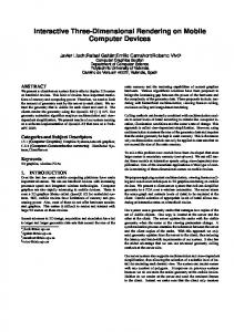
140000
with region growing no region growing 4.8fps 4.8fps
130000
warped pixels
120000
5.5fps
110000
5.9fps
100000
5.9fps
7.1fps 90000
5.9fps
6.25fps 6.6fps
80000 70000
visited pixels: 130.000 - 180.000 (with region growing) 130.000 - 150.000 (no region growing)
60000 50000 0
20
40 60 80 100 120 140 number of eye points in Lumigraph
160
Figure 6: Warped pixels / frame rate plotted against the number of eye points in the ’elephant’ Lumigraph. For the lower curve, warping source regions have not been extended at all. The upper curve was obtained using the global maximum (cf. Sec. 3.2). Rendering times are given for a 270 MHz SGI O2 (R12K). On a 300 MHz Octane, the rate goes up by 1.5–1.9. 4.2 Performance Issues The rendering time of the algorithm depends on several factors. The resolution of the image plane texture plus the region growing overhead determine the upper bound for the number of pixels to be processed. However, since the algorithm discards background pixels immediately, it is obvious that the main computation time is spent on the actually warped foreground pixels (cf. algorithm in Fig. 5). As discussed in Sec. 3.4, the number of processed pixels is nearly independent of the number of reference images. Figure 6 shows the number of foreground pixels as well as the frame rate for the “elephant” Lumigraph, for different numbers of reference images. The image plane resolution is 256x256 pixels, the maximum disparity 0.3. It can be observed that the rendering time increases sublinearly with the number of eye points, and the frame rate is proportional to the number of warped pixels. The difference of the two plotted curves nicely visualizes the constant overhead added by the region growing (cf. Sec. 3.2). Figure 11 shows a different artificial scene, rendered into a 36-image Lumigraph with 512x512 image plane pixels. The rendering time for this Lumigraph increases as expected due to the four times higher image plane resolution, but since the number of foreground pixels is similar to that in the elephant scene, we still obtain 4.8 frames/s for 95.000 warped pixels with region growing, and 5.5 fps for 70.000 pixels without region growing on an O2 (max. disparity is 0.5). The average number of vis-
ited pixels (including background) per frame is 212.000, as opposed to 140.000 for the elephant Lumigraph. We viewed the images at full screen resolution. As expected, the this does not affect the rendering time since the final texture mapping step is done in hardware. 4.3 Depth Quantization In all the example in this paper, the depth values have been uniformly quantized in the range [−D : D] before using them for the warping. Choosing a quantization of 8 bit does not affect the quality or performance of the algorithm at all, and it removes the need for a blending depth threshold � as explained in Sec. 3.3. In our experiments we found that even with 6 bit, the images appear quite sharp and clean. Only the extreme edges in the scene become a bit blurry (e.g. the elephant’s ear). When using less than 6 bit, the artifacts are similar to, but not as strong as those of light field interpolation. 4.4 Comparison with Previous Approaches Fig. 10 depicts the same view as Fig. 8, but computed through interpolation from a light field without depth information [9]. Even though we used twice the number of images than for Fig. 8, very strong blurring and ghosting artifacts appear. These are even visible for the 164-eye point light field. Fig. 12 shows the same scene as in Fig. 11, but rendered using depth-corrected Lumigraph rendering along the lines of [5]. The algorithm casts depth rays towards a coarse geometric model of the scene. If the three depth values for an eye point triangle differ, the triangle is subdivided adaptively, and more depth rays are used. If the algorithm does not detect any depth discontinuities using the initial depth rays, the adaptive scheme fails. This leads to the blurred edges similar to those in Fig. 12. Also, if a discontinuity is detected, quite a large number of depth rays (up to one per pixel along an edge) has to be cast in order to adapt the triangles to the edge. The computational cost of the approach depends on the depth continuity of the scene as well as on the number of geometric primitives used for approximating the scene. More experiments would be necessary in order to analyze these aspects in detail. From the tests with the implementation at hand, we learned that the algorithm becomes noninteractive as soon as more than 1000 triangles are used.
5 Conclusions and Future Work We presented an algorithm for rendering high-quality views of a Lumigraph at interactive rates. Using only a very small number of reference images (e.g. 25) and quantized depth values (6-8 bit), the algorithm produces no serious artifacts except when zooming in very close
to the image plane. Furthermore, the method’s computation time depends mainly on the number of pixels actually drawn on the image plane. The frame rate is nearly independent of the number of reference images used for the Lumigraph. The algorithm presents a hybrid method, bringing together the best of warping and image databases, since it organizes and restricts the reference images in such way that the artifacts and overhead are minimized for the rendering. Together with the adaptive acquisition scheme presented in [15], the algorithm can be employed for progressive transmission of Lumigraphs, for example in the world wide web. After loading only the first four images, the slab can be displayed, and the user can navigate around the object while some background process refines the Lumigraph by inserting the missing images as they are transferred. Standard image compression techniques can be applied to the Lumigraph images, and on-the fly decompression of pixel rows for warping seems to be feasible with our approach. It is very important to test how the algorithm performs on real-world data, which is a major aspect of image based rendering. The quantization of depth values is a first step in that direction and shows promising results. Furthermore, it would be interesting to see which parts of the algorithm could be implemented using advanced features of contemporary graphics hardware. We believe that our method may inspire many directions of future research. The most important and promising goal is to find an fully adaptive and hierarchical Lumigraph data structure that stores only little redundant information, but still allows for interactive rendering at multiple resolutions. Acknowledgements Thanks to Christian Vogelgsang (University of Erlangen) for his implementation of the Lumigraph rendering along the lines of [5], and to Pere-Pau Vazquez (University of Girona), who provided continuous encouragement and helped debugging a critical part of the implementation. Annette Scheel, Marc Stamminger, and Katja Daubert (Max-Planck-Institut für Informarik) provided kind support for acquiring the Lumigraph data using the in-house rendering system A NTELAO . The code for Delaunay triangulation was taken from Jonathan Richard Shewchuk’s TRIANGLE package, available from http://www.cs.cmu.edu/~quake/triangle.html.
6 References [1] E.H. Adelson and J.R. Bergen. Computational Models of Visual Processing, chapter 1 (The Plenoptic Function and the Elements of Early Vision). MIT Press, Cambridge, MA, 1991.
[2] E. Camahort, A. Lerios, and D. Fussell. Uniformly sampled light fields. In Proc. 9th Eurographics Workshop on Rendering, pages 117–130. Springer Verlag, 1998. [3] C.-F. Chang, G. Bishop, and A. Lastra. LDI tree: A hierarchical representation for image-based rendering. In Proc. SIGGRAPH 99, pages 291–298. Addison-Wesley, 1999. [4] S.E. Chen and L. Williams. View interpolation for image synthesis. In Proc. SIGGRAPH ’93, pages 279–288. Addison-Wesley, 1993. [5] S.J. Gortler, R. Grzeszczuk, R. Szeliski, and M.F. Cohen. The Lumigraph. In Proc. SIGGRAPH ’96, pages 43–54. Addison-Wesley, 1996. [6] W. Heidrich, H. Schirmacher, and H.-P. Seidel. A warping-based refinement of Lumigraphs. In V. Skala, editor, Proc. WSCG ’99, pages 102–109, 1999. [7] I. Ihm, S. Park, and R.K. Lee. Rendering of spherical light fields. In Proc. Pacific Graphics ’97, 1997. [8] A. Isaksen, L. McMillan, and S. J. Gortler. Dynamically reparameterized light fields. Technical Report MIT-LCSTR-778, MIT LCS, May 1999. [9] M. Levoy and P. Hanrahan. Light field rendering. In Proc. SIGGRAPH ’96, pages 31–42. Addison-Wesley, 1996. [10] W.R. Mark, L. McMillan, and G. Bishop. Post-rendering 3D warping. In Proc. 1997 Symposium on Interactive 3D Graphics, pages 7–16. ACM Press, 1997. [11] L. McMillan. An Image-Based Approach to ThreeDimensional Computer Graphics. PhD thesis, Department of Computer Science, University of North Carolina at Chapel Hill, Chapel Hill, North Carolina, 1997. [12] L. McMillan and G. Bishop. Plenoptic modeling: An image-based rendering system. In Proc. SIGGRAPH ’95, pages 39–46. Addison-Wesley, 1995. [13] M. M. Oliveira and G. Bishop. Factoring 3-D image warping into a pre-warp followed by conventional texture mapping. Technical Report TR99-002, Dept. of Computer Science, University of North Carolina at Chapel Hill, 1999. [14] G. Schaufler. Nailboards: A rendering primitive for image caching in dynamic scenes. In Proc. 8th Eurographics Workshop on Rendering, pages 151–162. Springer Verlag, 1997. [15] H. Schirmacher, W. Heidrich, and H.-P. Seidel. Adaptive acquisition of Lumigraphs from synthetic scenes. In Proc. EUROGRAPHICS ’99, pages 151–159. Blackwell Publishers, 1999. [16] J. W. Shade, S. J. Gortler, L. He, and R. Szeliski. Layered depth images. In Proc. SIGGRAPH ’98, pages 231–242. Addison-Wesley, 1998. [17] P.-P. Sloan, M.F. Cohen, and S.J. Gortler. Time critical Lumigraph rendering. In Proc. 1997 Symposium on Interactive 3D Graphics, pages 17–24. ACM Press, 1997.
Figure 7: A view of an elephant Lumigraph generated from only 2x2 images. You can see that the elephant appears very sharp, but there are visible disocclusions and highlight artifacts.
Figure 10: A view generated by the light field interpolation scheme from a 50-image Lumigraph. Despite the large number of images, there are very strong blurring and ghosting artifacts.
Figure 8: The same view, generated from a 25-image Lumigraph. The disocclusion artifacts are gone, and the highlight artifacts are only barely visible.
Figure 11: Lumigraph view of a simple scene, computed by warping from 6x6 images of 512x512 pixels resolution.
Figure 9: 25-image elephant Lumigraph, viewed from very close to the image plane. Gaps with the maximal width of 1 pixel can be observed (white spots).
Figure 12: Depth-corrected rendering of the same scene as in Fig. 11, according to the original Lumigraph hardware rendering algorithm [5]. Since the depth rays do not detect all edges, there is still a large amount of blurring.