Stereoscopy is an emerging field in cinematography and gaming. While generating stereo images is well known for standard projections, the implementation of.
INTERACTIVE STEREO RENDERING FOR NON-PLANAR PROJECTIONS OF 3D VIRTUAL ENVIRONMENTS With a Comparison of Image- and Geometry-based Approaches ¨ Matthias Trapp, Haik Lorenz, Jurgen D¨ollner Hasso-Plattner-Institute, University of Potsdam, Prof.-Dr.-Helmert-Str. 2-3, Potsdam, Germany {matthias.trapp | haik.lorenz | juergen.doellner}@hpi.uni-potsdam.de
Keywords:
Stereoscopic Imaging, Non-planar projections, Real-time rendering
Abstract:
Stereo rendering, as an additional visual cue for humans, is an important method to increase the immersion into 3D virtual environments. Stereo pairs synthesized for the left and right eye are displayed in a way that the human visual system interprets as 3D perception. Stereoscopy is an emerging field in cinematography and gaming. While generating stereo images is well known for standard projections, the implementation of stereoscopic viewing for interactive non-planar single-center projections, such as cylindrical and spherical projections, is still a challenge. This paper presents the results of adapting an existing image-based approach for generating interactive stereoscopic non-planar projections for polygonal scenes on consumer graphics hardware. In particular, it introduces a rendering technique for generating image-based, non-planar stereo pairs within a single rendering pass. Further, this paper presents a comparison between the image-based and a geometry-based approach with respect to selected criteria.
1
INTRODUCTION
Stereoscopy is the phenomenon of simultaneous vision with two eyes, producing a perception of the relative distances between objects in space. Stereoscopy can be created by using a stereo image pair displayed with active or passive stereo viewing concepts, which enable the experience of the stereo sensation. This feature is a requirement for 3D immersive digital environments. Creating stereo image pairs is straightforward for planar projections that can be accelerated by graphics hardware. The renderer needs to create an image pair, one image for the left eye and one for the right eye. Most of todays computer games and visualization frameworks offer a 3D stereo mode for standard planar projections. Enabling interactive stereo rendering for nonplanar projections is not a trivial problem. This is especially true for rendering on polygonal consumer graphics hardware without the support of parallel or distributed systems. The optimal solution for this problem enfolds the following attributes: It should enable rendering at interactive frame rates for largescale models, such as virtual 3D city models or land-
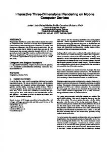
Figure 1: Application of a passive stereo rendering technique for immersive virtual environments.
scapes on current consumer hardware. Further, the approach should be applicable to multiple variants of single-center projections, support omni-directional stereo, deliver high-quality images, and should be easy to implement and integrate into existing rendering frameworks. Figure 1 shows a passive anaglyph stereo rendering of a 180◦ cylindrical projection performed in real-time, displayed on a half-cylindrical screen.
This paper presents the application of imagebased (IBA) and geometry-based (GBA) approaches for creating non-planar projections (NPP) to stereo rendering, and makes to the following contributions to the reader: It extends an image-based approach for generating non-planar projection described in (Trapp and D¨ollner, 2008) with the functionality of interactive rendering for active and passive stereo viewing. We present a new rendering technique that renders theses stereo images within a single scene rendering pass. The paper gives explanations for the implementation using modern graphics hardware. We further present a performance evaluation of the extended rendering technique as well as a comparison between IBA and GBA described in (Lorenz and D¨ollner, 2008) by using different criteria. This paper is structured as follows. Section 2 gives an overview of related and previous work concerning our topic. Section 3 introduces the basic concepts of stereoscopic rendering and reviews the image-based and geometry-based approaches for generating nonplanar projections. Section 4 focuses on the implementation of our rendering technique and presents a performance evaluation. Section 5 compares IBA and GBA. Section 6 discusses of the results and concludes the paper.
2
RELATED & PREVIOUS WORK
Besides approaches for omni-directional non-planar projections and camera systems (Peleg et al., 2001) that stitch real-world images to obtain a still stereo image, we find approaches for stereo rendering on multi-projector systems (Bimber et al., 2005). This work reflects non-planar projections for single projection centers which can be created using image-based and geometry-based approaches. We focus on the last two. Image-based Approaches These rendering techniques are mainly based on two phases. First, a raster representation of the virtual scene is created using offscreen rendering. In the second phase, this representation is used to create different projections or imagedistortions using image warping in a post processing step (Yang et al., 2005). In (Trapp and D¨ollner, 2008) a generalization of this approach is described that uses a cube map texture to represent the virtual environment and create multiple NPPs and variants of image distortions. Geometry-based Approaches A straight-forward GBA implementation simply projects all mesh ver-
tices non-planarly and rasterizes the primitives immediately (Spindler et al., 2006). The inadequate linear interpolation during rasterization requires highly tessellated meshes for artifact-free renderings. Dynamic mesh tessellation based on instancing (Boubekeur and Schlick, 2008; Tatarinov, 2008), geometry shaders (Lorenz and D¨ollner, 2008), or hardware tessellation units (Tatarchuk, 2007) can ensure this property for arbitrary meshes. An alternative approach is tessellating the non-planar projection into smaller and simpler projections. (Hou et al., 2006) describes an approach for rendering arbitrary projections which is conceptually based on beam tracing.
3
BASIC CONCEPTS
Regardless of the rendering techniques used for creating non-planar projections, the creation of stereoscopic views comprises the following two basic steps: 1. Generating Stereo Pairs: The NPP for the left and right images are synthesized by using imagebased or geometry-based rendering techniques. 2. Stereo Rendering: The stereo pairs are combined into a single frame buffer (passive stereo) or rendered into two frame buffer (active stereo) by using post-processing compositing passes.
3.1
Image-based Projections
Before we describe how to create stereo renderings for non-planar projections, we briefly review the approach described in (Trapp and D¨ollner, 2008). This approach uses a dynamically created cube-map texture to capture the complete virtual environment that surrounds the virtual scene camera. The non-planar projections are derived by applying a projection function δP that samples the cube map using computed normal vectors. This functionality is implemented in a fragment shader program using a post-processing pass. It is activated when rendering a screen-aligned quad that covers the whole view port. This paper adapts and extends the described concept to support stereo rendering. A na¨ıve approach is the creation of two cube maps using two rendering passes and then perform stereo rendering by computing two non-planar projections. To avoid unnecessary state changes for multi-pass rendering, we propose a method that creates two cube map textures within a single rendering pass. This fully hardwareaccelerated technique is described in Section 4. It integrates into the referenced image-based approach, and therefore benefits from further functionality such as generalizations of non-planar projections.
Figure 2: Overview of the implementation concept for image-based stereo rendering for non-planar projections. Layered rendering is used to create image representations of the input geometry. These images are synthesized into stereo pairs of non-planar projections which are then viewed in stereo.
3.2
Geometry-based Projections
Object-space approaches do not rely on resampling of an intermediate texture to achieve the non-planar projection effect. They apply the projection directly to mesh vertices and render the final image immediately using regular rasterization. At this point, we summarize the approach taken by (Lorenz and D¨ollner, 2008). They use geometry shaders to generate a viewdependent tessellation with limited edge length per primitive. For performance, they rely on an intermediate mesh using barycentric coordinates. Since geometry shaders are currently not capable of emitting sufficient primitives at once, a three-pass scheme is used: first, the required tessellation level is determined per original primitive. Second, the existing tessellated intermediate mesh is refined to meet the new tessellation requirements. Third, the intermediate mesh is converted into a fully attributed mesh, projected, and rendered to the screen. To enable stereo rendering, layered rendering can be used to create both images at once. The third pass simply emits each primitive twice using separate projections and directs them into two different layers. A subsequent compositing pass creates the stereo view.
4
IMPLEMENTATION
Our exemplary implementation is based on OpenGL (NVIDIA, 2008) and the OpenGL shading language (Kessenich, 2006). The GBA enables the direct output of the stereo pair using a single scene evaluation and is not discussed furthermore. This section focuses on the extension of the IBA to create the raster representation within a single scene rendering pass. Figure 2 shows an overview of our implementation concept. The rendering process for creating stereo pairs enfolds the following three steps per frame: 1. Update Camera Orientation: The twelve camera orientations for all cube-map faces are updated using the parallel camera mode. The off-axis and
toe-in camera modes (Bourke and Morse, 2007) are not used, since they lead to artifacts or missing stereo disparity. 2. Create Raster Representations: There are three alternatives for creating raster representation of the virtual 3D scene. The first uses multi-pass rendering to create two cube-map textures by rendering one pass for each cube map face, i.e., twelve passes in total. The second requires one pass for each cube-map texture by using renderto-cubemap (RTC), i.e., two passes in total. The third creates twelve layers, corresponding to each face of two cube maps textures, within a single rendering pass. This section focuses on the third alternative. 3. Apply Projection: The raster representations are transformed into two non-planar projections (left, right). This is done in one or two full-screen postprocessing passes using a single frame buffer for passive stereo rendering or a dual frame buffer for active hardware stereo rendering.
4.1
Creating Raster Representations
The present generation of raster-based polygonal rendering hardware (Blythe, 2006) enables the application of layered rendering or RTC. Using the support of geometry amplification, there are two possibilities to create a raster representation of the virtual scene: render to twelve layers interpreted as faces of two cube-map textures or render to six layers interpreted as a single cube-map texture with two render targets by using multiple render-targets (MRT). Currently, there is a lack of support for multiple depth buffers. Thus, using MRT is not possible because both targets would share the same depth buffer. This would lead to incorrect rendering results. However, the first approach requires the binding of two cube map textures to a frame buffer object. Unfortunately, this is not possible due to API restrictions (OpenGL and Direct3D). Therefore, we perform rendering to twelve 2D texture layers and interpret them
#version 120 #extension EXT_geometry_shader4 : enable uniform mat4 VPM[12];//View projection matrices bool cullViewFrustum(in vec4 P[3]) { const vec4 plane = vec4(-1.0, -1.0, 1.0, 1.0); vec4 T[3]; T[0] = clamp(P[0].xyxy * plane - P[0].w,0.0,1.0); T[1] = clamp(P[1].xyxy * plane - P[1].w,0.0,1.0); T[2] = clamp(P[2].xyxy * plane - P[2].w,0.0,1.0); return !any(notEqual(T[0]*T[1]*T[2], vec4(0.0))); } bool cullBackFace(in vec4 P[3]) { vec2 d0 = P[1].xy * P[0].w - P[0].xy * P[1].w; vec2 d1 = P[2].xy * P[0].w - P[0].xy * P[2].w; float w = min(min(P[0].w, P[1].w), P[2].w); return d1.x * d0.y < d0.x * d1.y || w