Eurographics Symposium on Rendering (2004) H. W. Jensen, A. Keller (Editors)
An Interactive Out-of-Core Rendering Framework for Visualizing Massively Complex Models Ingo Wald†‡ , Andreas Dietrich‡ , and Phlipp Slusallek‡ † MPI
Informatik, Saarbrücken, Germany,
[email protected]
‡ Saarland University, Saarbrücken, Germany {dietrich,slusallek}@cs.uni-sb.de
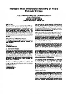
Figure 1: The “Boeing 777” model containing 350 million triangles. a.) Overview over the entire model, including shadows. b.) Zoom into the engine, showing intricately interweaved, complex geometry. c.) The same as b.), but zooming in even closer. All of the individual parts of the entire plane are modeled at this level of complexity. d.) The cockpit, including shadows. Using our out-of-core visualization scheme, all of these frames can be rendered interactively at 3–7 frames per second on a single desktop PC.
Abstract With the tremendous advances in both hardware capabilities and rendering algorithms, rendering performance is steadily increasing. Even consumer graphics hardware can render many million triangles per second. However, scene complexity seems to be rising even faster than rendering performance, with no end to even more complex models in sight. In this paper, we are targeting the interactive visualization of the “Boeing 777” model, a highly complex model of 350 million individual triangles, which – due to its sheer size and complex internal structure – simply cannot be handled satisfactorily by today’s techniques. To render this model, we use a combination of real-time ray tracing, a low-level out of core caching and demand loading strategy, and a hierarchical, hybrid volumetric/lightfield-like approximation scheme for representing not-yet-loaded geometry. With this approach, we are able to render the full 777 model at several frames per second even on a single commodity desktop PC. Keywords: Real-time rendering, out-of-core rendering, complex models, distributed computing, ray tracing Categories and Subject Descriptors (according to ACM CCS): I.3.7 [Computer Graphics]: Ray tracing I.6.3 [Simulation and Modeling]: Applications I.3.2 [Computer Graphics]: Distributed/network graphics
1. Introduction For many years now, the performance of commodity CPUs has increased at a rate of a factor of two roughly every 18 months. At least in the last few years, the performance of graphics hardware has grown even faster, having led to commodity graphics hardware that can render up to several million triangles per second. In addition to this “free” increase in rendering performance, we also see a steady improvement in rendering algorithms. With all this taken together, the model complexity that is affordable at interactive rates is constantly and rapidly increasing. c The Eurographics Association 2004.
Unfortunately, the complexity of practical models seems to be rising even faster: First of all, users of modeling systems (and game designers as well) tend to immediately spend every grain of increased performance into even more detail, i.e. into more triangles. Additionally, virtual prototyping is becoming increasingly important and hardwired into the design process. Traditionally, virtual reality has been but loosely coupled to the actual design process, and has merely visualized semi-manually prepared (i.e. simplified) versions of the CAD models. With VR getting increasingly involved into the production pro-
Wald, Dietrich, Slusallek / Interactive Out-of-Core Rendering for Massively Complex Models
Figure 2: Some example closeups of the 777, to show the high geometric complexity, small degree of occlusion, and complex topological structure of the model, which make it complicated for most simplification/approximation-based approaches. a.) Zoom onto a small object of roughly one cubic foot in size, showing each individual nut and bolt modeled with hundreds of badly-shaped triangles. Multiple surfaces with different materials overlap themselves, as can be seen e.g. on the mixed white/blue-patched structure. Due to the randomly jittered vertex positions (introduced to prevent data theft), such structures self-intersect with each other randomly. b.) The same view from a few meters away. The left image corresponds to the red rectangle in the middle. c.) & d.) The same for a view into the engine. Note how much detail is visible in that view, and how the many pipes and cables are intricately interweaved. The low degree of occlusion is also demonstrated in Figure 3. cess, there is a growing need to render models “directly out of the database”, i.e. without any model “preparation” and simplification. Such CAD datasets, however, can be quite complex. Furthermore, the increased use of “collaborative engineering” for large-scale industrial projects leads to models consisting of hundreds and thousands of individual parts (potentially created by different suppliers), each of which modeled at whatever complexity and accuracy has been affordable for that individual part. In practice, this often means that each individual nut and bolt of a model (also see Figures 1– 3) is represented in full geometric detail. Taken together, these developments lead to a growth in model complexity that seems to be at least as fast as the growth in hardware resources. An end to these developments currently is not foreseeable. In this paper, we are targeting the interactive visualization of the “Boeing 777” model, a model consisting of roughly 350 million individual triangles, i.e. without using instantiation to generate this triangle count. Just the raw input data of that model ships – in compressed form – on a total of eleven CDs. After unpacking and storing each triangle as a triple of three floats without any additional acceleration data, the model is 12 GByte in size, and requires several minutes just for reading it from disk. For this kind of model complexity, generating frame rates of several frames per second is quite challenging for contemporary massive model rendering approaches. 1.1. Outline In the remainder of this paper, we will first discuss relevant related work regarding rendering complex models in Section 2, and will particularly discuss their problems in handling a model of the size, topological structure, and complexity of the 777. Based on this discussion, we will then
develop and describe our new approach to such models: After giving an overview of our system in Section 3, we will then describe the caching and demand loading subsystem in Section 4, and our hierarchical approximation scheme for not-yet-loaded geometry in Section 5. Section 6 then summarizes some results of using our framework for rendering the full 777 model on a single dual-1.8 GHz AMD Opteron desktop PC with 6 GB RAM. Finally, Section 7 concludes and ends with an outlook on future work. 2. Previous Work Due to the practical and industrial importance of rendering complex datasets, there exists a vast suite of different approaches to this problem. However, many of these techniques perform well only for specific kinds of models, but prove problematic for others. Brute-Force Rendering. Obviously, a model of the size of the 777 cannot be handled by a pure brute-force approach. In theory, the most up-to-date graphics hardware (e.g. an NVIDIA Quadro FX 4000) features a theoretical peak performance of 133 million shaded and lit triangles per second, and could thus raster the full model in only a few seconds. Unfortunately, the practical performance usually is much lower, in particular for models that do not fit into graphics card memory. Thus, typical approaches to rendering complex datasets rely on reducing the number of triangles to be sent to the graphics card. Culling Techniques. Typical approaches like view-frustum culling are quite limited for a model of as high a depth complexity as the 777. Depth complexity can only be handled by taking occlusion into account. At least for 2D or 2 12 D scenes (e.g. urban walkthroughs), occlusion can be conservatively precomputed quite well [WWS00]. In three dimensions, in particular with as few occlusion as in the 777 (see Figures 2 and 3), visibility preprocessing is quite problematic [ACW∗ 99]. c The Eurographics Association 2004.
Wald, Dietrich, Slusallek / Interactive Out-of-Core Rendering for Massively Complex Models
Instead of precomputing visibility, the alternative is to use a hierarchical visibility culling mechanism, e.g. the hierarchical z-buffer [GKM93], possibly implemented via OpenGL occlusion queries [BMH99]. However, neither of these approaches has been designed for handling gigabytesized models that do not even fit into main memory. Recently, Correa et al. [CKS03] have proposed a visibilitybased out-of-core rendering framework that can also cope with models larger than memory. However, even if visibilitybased approaches would achieve perfect culling, for many views the low degree of occlusion in the 777 still results in millions of potentially visible triangles. To handle this case, the randomized z-buffer algorithm [WFP∗ 01] randomly selects one triangle out of the many triangles that project onto a pixel. This, however, works only for scenes in which it does not actually matter which of the triangles is chosen, e.g. for picking one of the thousands of leaves of a tree. For the 777 the exact ordering and mutual occlusion of even very close-by triangles is quite important. For example, in order to avoid the small yellow pipes “shining through” the green hull to which they are attached. Finally, like all the previously mentioned techniques, the randomized z-buffer is not designed for handling models that do not even fit into memory. Model Simplification. As pure visibility culling even theoretically is not enough, many approaches try to “reduce” the model by some form of mesh simplification, e.g. via edge contraction, vertex removal, or remeshing (see e.g. [CMS98]), often requiring some form of “wellbehaving” geometry. Typically, these methods perform best for highly tessellated surfaces that are otherwise relatively smooth, flat, and topologically simple. In the 777 the triangles actually form many detailed, loosely connected though interweaving parts of complex topological structure, such as mazes of tubes, pipes, and cables (see Figures 2 and 3). Such kinds of geometry are very hard to simplify effectively in a robust manner. Moreover, each part of the 777 comes in a “soup” of unconnected triangles, without any connectivity information, often forming self-intersecting and overlapping surfaces (see
Figure 3: In comparison to most other “massive” models, the 777 has a much lower degree of occlusion. a.) Zoom onto the front part of the model, where the rays penetrate deeply into the model. b.) Closeup of the geometry that can be seen through the ribs of the plane. c The Eurographics Association 2004.
Figure 2a) with different material properties. Even worse, the vertex positions have been slightly jittered to prevent public spreading of the sensitive original CAD data. Thus, overlapping surfaces are not perfectly aligned, but rather randomly intersect each other multiple times. For such kinds of input data, most geometrically based algorithms are likely to fail. As each individual technique usually has a weak point, the UNC’s MMR/Gigawalk system [ACW∗ 99, BSGM02, GLY∗ 03] is based on a combination of different techniques, combining mesh simplification, visibility preprocessing, impostors [SDB97], textured depth meshes, and hierarchical occlusion maps [ZMHH97]. However, as just discussed each of these individual parts is problematic in the 777. This raises the question whether a combination of these techniques can still succeed in each technique masking the shortcomings of the other. Image-based and Point-based Approaches. In addition to these “traditional” methods, researchers have also looked into image-based and point-based approaches. For example, the Holodeck [WS99], Render Cache [WDP99], and Edge-and-Point-Image [BWG03] progressively sample the model asynchronously to displaying it, and interactively reconstruct the image from these sparse samples. In principle, both approaches might be applicable to the 777. However, the rays traced by these systems are likely to cause significant paging, resulting in prohibitively long times for generating enough image samples. This is likely to result in severe subsampling, and in strong visual artifacts. As yet another alternative, researchers have proposed to represent models using point samples (see e.g. [CH02, PZvBG00]). Though this decouples geometric complexity from display complexity, the sparse number of samples often limits the detail that is present in the reconstructed image. To avoid this problem, QSplat [RL00] employs a hierarchical scheme in which the entire mesh is represented by at least one sample per triangle. However, its hierarchical approximation scheme assumes that nearby triangles can, if seen from a distance, be well approximated by a disk-shaped “splat” with filtered color and normal information. Like mesh simplification, this works only for relatively smooth and topologically simple surfaces, and is likely to fail for the geometrical structure of the 777 as described above. Interactive Ray Tracing. Finally, complex models can also be visualized using interactive ray tracing. Due to its logarithmic dependence on scene complexity, ray tracing can easily handle even highly complex scenes of several million triangles at full detail. For example, the OpenRT realtime ray tracing system [Wal04] has been shown to interactively render the one billion triangle “Sunflowers” scene even including shadows, semi-transparent leaves, and moving geometry. However, this has only been possible through
Wald, Dietrich, Slusallek / Interactive Out-of-Core Rendering for Massively Complex Models
instantiation, i.e. by reusing the same kind of sunflower several thousand times, therefore being able to keep the entire model in main memory. For the 777 model, we simply cannot store the entire dataset – which occupies 30–40 GByte including acceleration structures – in main memory. Once the operating system starts to generate the inevitable page faults the ray tracer would run idle while waiting for data, and could not maintain interactivity. In order to solve that problem, Pharr et al. [PKGH97] have proposed a caching and reordering scheme that reorders the rays in a way that minimizes disk I/O. Though this allows for efficiently ray tracing models that are much larger than main memory, the approach is not easily applicable to interactive rendering. A simplified version of this scheme has also been used by Wald et al. [WSB01]. They have proposed to “suspend” rays that would cause a page fault and load the required data asynchronously over the network while tracing other rays in the meantime. The stalled rays then get “resumed” once the data is available. Though that approach worked well for the target model (the 12.5 million triangle UNC Power Plant), it fails in interactively rendering a model as complex as the 777: The proposed suspend/resume approach can hide the loading latency only within the duration of one frame. In the 777, however, even a small camera change often triggers thousands of disk read requests that simply cannot be fulfilled within a single frame. Though prefetching (in the sense of e.g. [CKS03]) would help, it can hide loading latencies only to a limited degree. Furthermore, their demand loading scheme was based on splitting the model into “voxels” of several thousand triangles, which were then loaded and discarded as required. This caching granularity is far too large for our purposes, as each individual ray may cause loading another of these voxels. Additionally, this method is prone to memory fragmentation, and carries a certain overhead for managing the data (also see the discussion in [DGP04]). 3. An Out-of-Core Framework for Interactively Rendering Massively Complex Models As shown by the discussion in the previous section, contemporary techniques to handle massive models cannot easily cope with a model of the size, structure, and complexity of the 777. Thus, a new approach had to be taken. Since ray tracing can in principle handle such massive amounts of geometry, in a first experiment we ported the OpenRT ray tracer to a shared-memory architecture, and experimented with rendering the 777 on 16 UltraSPARC III CPUs in a SUN Sun Fire 11K with 180 GB RAM. This allowed for storing the model – including pre-built BSP data – into the RAM disk, making it possible to load the entire scene within a few seconds, and to interactively inspect it at several frames per second, even including shadows. With these successful experiments, we started designing
an architecture that could deliver similar performance even on a commodity PC. In order to be able to at least address the entire model, we decided to build on AMD’s 64-bit Opteron CPUs [AMD03], which have recently become available in commodity desktop systems. Compared to e.g. the Intel Itanium CPU, the Opteron also supports the IA32 SSE Instruction set [Int02], and thus can exploit also those traversal and intersection routines of OpenRT that have been specifically optimized towards SSE [WSBW01, Wal04]. This support for using SSE instructions – together with a nominally higher clock rate – allow the Opteron to easily outpace the UltraSPARC III. Instead of having to use many CPUs in a Sun Fire, we can achieve similar performance on a single dual-CPU Opteron PC. Unfortunately, having a 64-bit address space allows for addressing the entire model, but cannot help the fact that we still are not able to keep it entirely in memory. We therefore decided to follow the approach of Wald et al. [WSB01], and use a combination of manual memory management and demand loading in order to detect and avoid page faults due to access to out-of-core memory. As discussed in the previous section, however, their approach had several shortcomings with respect to a 777-class model, mainly with respect to the design and implementation of the memory management scheme. Most importantly, their system has mainly been designed for hiding the scene access latency by suspending and resuming rays, which we have argued cannot work successfully for the 777. As a consequence, our framework builds on two pillars: First, on a new memory management scheme that has been redesigned from scratch. It avoids the fragmentation, caching granularity, and I/O problems of the original approach, and is thus much better suited for a 777-class model. Second, our approach does not even try to hide scene access latency, but instead kills off potentially page-faulting rays, which are then being replaced by shading information from so-called “proxies”. This is achieved by efficiently determining in advance accesses to parts of the BSP that may potentially lead to a page fault. Proxies are a pre-computed coarse yet appropriate approximate representation for the respective subtree. This proxy mechanism is similar to a hierarchical level-of-detail representation intermixed with the spatial index structure, and will be described in more detail in Section 5. 4. Memory Management As just motivated, a memory management scheme based on manually managing individual sub-parts of several thousand triangles is inappropriate for the 777 due to memory fragmentation, much too coarse cache granularity, and thus bad memory efficiency and high I/O cost. In contrast to this, the Linux/UNIX memory mapping facilities (mmap() [BC02]) provide a convenient way of addressing and demand loading memory on a per-page basis. In particular, it realizes c The Eurographics Association 2004.
Wald, Dietrich, Slusallek / Interactive Out-of-Core Rendering for Massively Complex Models
a unified cache, i.e. it does not matter which data is contained in which physical page, and it never pages in any data (e.g. shading information) that might not be required. Leaving the memory management (MM) to the operating system greatly simplifies the design, and improves the efficiency of the implementation: For example, manual memory management requires to take special care in order to avoid race conditions where one thread accesses data that is just being freed by another thread. If not avoided by costly synchronization via mutexes, such race conditions usually lead to program crashes. If a similar race condition happens in our OS-based MM scheme, the worst that can happen is a page fault, as the pointer to the not available memory region is still considered valid. Additionally, working on “real” pointers minimizes the address lookup overhead, as this is done automatically by the processor’s hardware MMU, and do not cost precious CPU time (also see [DPH∗ 03]). Finally, using this scheme is quite simple: All one has to do to implement this scheme is to precompute all static data structures (e.g. BSP index structures etc.), store them on disk in binary form, and map them into the address space via mmap(). This preprocessing is done in an out-of-core approach similar to [WSB01]. 4.1. Detecting and Avoiding Page Faults Though an OS-based MM system has many advantages over manual caching, it also has a major drawback in that we lose control over what data is loaded into or discarded from memory at what time. Although data is automatically paged in on demand upon accessing it, the resulting page fault stalls the rendering thread until the data is available. To retain control over the caching process we implemented a hybrid memory management system, which uses the operating system to perform demand paging, but which detects and avoids potential page faults before they occur, and which manually steers page loading and eviction. In order to avoid page faults, we have to detect whether or not memory referenced by a pointer is actually in core memory. Though Linux for this purpose offers the mincore() function, performing an OS call on each memory access obviously is not affordable. When taking a closer look at the Linux memory mapping implementation, however, there are several important observations to be made: First, after having once loaded a page, it will stay in memory at least for a limited amount of time. Second, pages in memory will not be paged out as long as there is some unused memory available. Thus, as long as we know that there is some memory left, we can mark once-accessed pages, and can be (almost) sure that the respective page will still be in memory later on. Obviously, this only works as long as we do not try to page in more data than fits into physical memory. Fortunately, this can be easily guaranteed: By using the Linux madvise() c The Eurographics Association 2004.
call, we can force the kernel to free pages of our choice, thereby guaranteeing that some free memory is available at any time, and that no pages become unavailable without us knowing it. Of course, this assumes that no other processes start using up our memory. 4.2. The Tile Table In order to mark pages as either available or missing, we have to store at least one bit per page. Keeping an entry for each potential 4 KB page in a 64-bit address space would require 252 entries and is not affordable. Instead, one could use a hierarchical scheme as used by the processor’s MMU, which however would be quite costly to access. We therefore group several pages into one “tile” and keep our tiles organized in a hash table of tile addresses. If the hash table is large enough to minimize hash collisions, hashing is quite efficient, and can be implemented with a few bit operations on the address pointer. Furthermore, a hash table is quite memory efficient: For hashing 128 GB RAM of 4 KB sized tiles (one page per tile) we only need 32M entries. Using a larger cache granularity of 16 KB or 64 KB, this reduces even more to 8M and 2M entries, respectively. If the size of the tile table is a power of two, all addressing and hashing operation can be performed efficiently by simple binary ands and shifts. Each tile table entry contains a 64-bit pointer with the virtual base address of the tile for detecting hashing collisions. The lower 12–16 bits of this entry are always zero, and can thus be used for other purposes, i.e. for marking whether the page is available (bit 0), and whether it has recently been referenced (bit 1). Thus, in order to check if a page is in memory, we simply have to find its entry in the tile table (one shift operation), validate there is no hash collision (one and), check bit 0 for availability (one more and), and, if required, set bit 1 (one or) to mark an access. 4.3. Tile Fetching In case we found a tile that is not marked as available, we cancel the respective ray and schedule the tile’s address for asynchronous loading by putting it into a request queue. Once a tile is scheduled to be fetched, it will eventually be loaded by an asynchronous fetcher thread. In an infinite loop, this thread in each iteration takes one request from the request queue, reads in the page via madvise(), and then marks the tile as available. Though reading the page obviously stalls the fetcher thread, the ray tracing threads are not affected at all, and remain busy. Note that we run several (4–8) fetcher threads in parallel, thereby allowing the OS to schedule multiple parallel disk requests as it deems appropriate. Fetch Prioritization. Missing data leads to cancellation of rays, so missing data that cancels many rays should be
Wald, Dietrich, Slusallek / Interactive Out-of-Core Rendering for Massively Complex Models
overview engine wheels cockpit cabin Figure 4: Reference views for our experiments. From left to right: Overview over the whole model, a view into the engine, zoom onto the front wheels, the cockpit, and one of the main cabins. Using a single dual-CPU AMD Opteron 1.8 GHz PC, these respective views can be rendered at 4.1, 2.9, 7.1, 3.1, and 3.2 frames per second at video resolution (640 × 480). fetched faster than data affecting only a single ray. Counting the actual accesses to a tile, however, is too costly, as it would require to coordinate the different write accesses to the shared counter. Instead, we observe that the number of affected rays is proportional to the size of the BSP voxel they are about to enter, and inversely proportional to its distance to the camera. We use this value for prioritizing fetch requests. To avoid searching for the most important requests, we map the priority to 8 discrete values, and keep one request queue for each of them. The fetchers then always take the first entry out of the queue with highest priority. This mapping is performed linearly, relative to the minimum and maximum priorities of the previous frame. 4.4. Tile Eviction As mentioned before, the tile fetcher can only fetch new tiles if some unused memory is available. Otherwise, the OS pages out tiles without us even noticing it (i.e. they are still being marked available). We therefore use the madvise() function to discard mapped pages from main memory. This obviously should be done only for pages that are likely not needed any longer. As a full “least recently used” strategy would be too expensive, we follow the same strategy as the Linux kernel swapper, and use a “second chance” strategy. The tile evictor slowly but continuously cycles through the tile table and resets the tile’s “referenced” bit to zero (the page is still marked as present!). If the tile is still needed, this bit will soon be re-set by a rendering thread. If, however, the evictor visits a tile a second time with the R-bit still zero, it evicts the tile and marks it as missing. Similar to the Linux kernel swapper, tile eviction only starts once memory gets scarce, currently at a memory utilization of ∼80%. 4.5. Minimizing MM Overhead While the just described memory management is an integral part of our system, we have to keep its performance impact to an absolute minimum. In particular, we have to minimize the number of semaphore synchronization operations, which otherwise tend to block the rendering threads. Apart from the time consumed by the asynchronous fetcher and evictor threads, the main ray tracing threads have
to constantly check each memory access for availability of the data. To minimize this overhead, we first check each pointer dereference for whether it crosses a tile boundary (with respect to the previous access). This can be done quite efficiently by simple bit operations, already reduces most of the tile table lookups, and does not require any costly semaphore operations. Even in the case that we have to access the tile table, we can often get away without having to perform locking operations: If the tile is marked as available, or is marked as already being fetched, we can immediately return. Though this can result in a race condition – e.g. the evictor might evict the tile at exactly this moment – this event is extremely improbable. Even if it occurs, in the worst case it can lead to either a single, improbable page fault, or to scheduling a tile twice for being loaded. Both cases are well tolerable even in the rare event that they occur. As such, there are only two cases where a ray tracing thread has to use a mutex. Once it adds a previously unvisited tile to the tile table, and every time it has to add a tile to the request queue. Both cases happen but relatively rarely. We also have to lock a mutex every time the tile fetcher or tile evictor want to modify the tile table or request queues. These threads, however, are not performance critical. 5. Geometry Proxies Using our MM scheme, we can efficiently detect and avoid any page fault of the ray tracing threads, and thus maintain interactivity and high performance at all times. Unfortunately cache misses are detected but shortly before the data is actually required. Thus, the ray that caused this page fault obviously cannot be traversed any further. As already discussed in Section 2, only suspending that ray until the data has been fetched will not work for a model of the 777’s complexity, as we simply cannot load thousands of tiles within a single frame. Hence, we have no other way but to accept the fact that there eventually will be pixels in a frame for which we cannot completely trace the necessary ray(s). Therefore, we have to decide on what color to assign to such pixels. Obviously, coloring these pixels in a fixed color (like red in Figure 5) results in large parts of the image being unrecognizable. c The Eurographics Association 2004.
Wald, Dietrich, Slusallek / Interactive Out-of-Core Rendering for Massively Complex Models
ory, and only small subtrees close to the leaves are likely to be missing. These subtrees fortunately are quite small, and, when projected, often smaller than a pixel. For such small voxels it often does not matter which triangle exactly is hit by the ray, as long as there is some kind of “proxy” that mimics the subtrees appearance. As a result, we have chosen to compute such a proxy for each potentially missing subtree. Note that this scheme is inherently hierarchical, as each proxy represents a subtree that in turn contains other subtrees and proxies. Moreover, this hierarchical approximation is tightly coupled to the BSP tree, and thus adapts well to the geometry.
Figure 5: Approximation quality during startup time. Left: Immediately after startup. Right: after loading for a few seconds. Even then only a fraction of the model has been loaded. Top row: Without proxy information, by just marking canceled rays in red. Bottom row: Using our geometry proxies. While the proxy quality after startup is quite coarse, it suffices to navigate the model. As can be seen, without the proxies almost no pixel contains sensible information. Eventually all data will be loaded, with no artifacts left at all. Also note that the positive influence of the proxies can hardly be shown in a still image, and becomes fully apparent only while interactively navigating the model. Alternatively one could fill in such a pixels color from the nearest valid sample, interpolate its color from several surrounding pixels, or even do sophisticated sparse sample reconstruction as done in e.g. the Render Cache [WDP99]. This approach however is quite problematic too: First, it requires costly (and badly parallelizable) post-filtering of the rendered image, which is too costly for full-screen resolutions. More importantly however, even a slight change of camera position can result in large fractions of the image becoming invalid (see Figure 5): Though most of the required nodes in the upper BSP levels will be in memory, many of the subpixel-sized leaf voxels will not yet be available, and will result in killing off many pixels, even after the rays could be traced “almost” up to he final hitpoint. 5.1. Proxies for Missing Data For a cache miss however there are several important observation to be made: First, a cache miss can only be caused by a ray that wishes to traverse a specific subtree of the BSP that is not yet in memory. Such a subtree – no matter how many nodes or triangles it contains – is always a volume enclosed in an axis-aligned box. Furthermore, walkthrough applications tend to not change the view drastically, and similar views will touch similar data, particularly in the upper levels of the BSP tree. As such, going from one view to the next most of the upper-level BSP nodes will already be in memc The Eurographics Association 2004.
Number of Proxies. Before discussing how exactly we are going to represent our proxies, we first have to evaluate how many of them we actually need (in order to estimate the amount of memory we can spend on them), and how to efficiently find the proxies. As we want to use our proxies for hiding the visual impact of a cache miss, we obviously need a proxy for each potentially occurring cache miss. As already discussed above, cache misses can only happen when following pointers from a parent node to its children that are located in a different tile. Instead of building a proxy for each child, we only build a proxy for the parent node. More importantly, we change our BSP memory organization such that the number of pointers across tiles is minimized: Instead of storing BSP nodes in depth-first order [Wal04], we now use a scheme where we always fill cache-tile sized memory regions in breadth-first order [Hav99], thereby combining nodes forming small subtrees in the same tile. Apart from having fewer tile-crossing pointers, this has the positive and visually notable side effect that the proxy distribution is more symmetric: In depthfirst order, the parents tile is usually filled up with nodes of the left child’s subtree, almost always yielding a potentially faulting pointer for the right son. This insymmetry results is visually displeasing images while not all data is loaded. granularity BSP deep shallow
16KB number
memory
64KB number
memory
15.6M 833K
1.2GB 66MB
4.3M 383K
344MB 30MB
Table 1: Number of proxies with respect to cache granularity, and for two different BSP tree parameters. The deeper BSP generates somewhat faster performance (see Table 3), but requires more memory and many more proxies. For our experiments, we typically use the shallow BSP with 16 KB tiles, resulting in less than 70 MB of proxy memory. However, using only 80 bytes per proxy (see below), even the deep BSPs are affordable when using 64 KB tiles, using 344 MB out of 6 GB RAM. Note that the deep BSPs are a worst-case configuration. Obviously, the exact parameters with which the BSP was
Wald, Dietrich, Slusallek / Interactive Out-of-Core Rendering for Massively Complex Models
built influences the number of proxies. Deeper BSPs tend to achieve higher performance (see Table 3), but unfortunately also have more potentially page-faulting subtrees (see Table 1). Note that we can also influence the number of proxies by adjusting the caching granularity, as we can also perform our caching on e.g. 16 KB or 64 KB tiles. A larger cache granularity results in less tiles, in less pointers crossing tile borders, and thus in less proxies (see Table 1). Due to their lower memory consumption, by default, we use the shallow BSPs with a cache granularity of 16 KB, resulting in roughly 1.1 million proxies for the 777 model. 5.2. Hybrid Volumetric/Lightfield-like Proxies As proxies, we have chosen a lightfield-like approach: As just argued, each proxy represents a volumetric subpart of the model, that will be viewed only from the outside, but from different directions. Thus, we only need to generate some meaningful shading information for each potentially incoming ray. This representation of discretized rays in fact is similar to a lightfield [LH96], except that we do not store readily shaded illumination samples in our proxy, but rather pre-filtered shading information. In particular, we store the averaged material information (currently only a single diffuse 5+6+5 bit RGB value) and the averaged normal (discretized into 16 bits). As mentioned above such a proxy will usually be subpixel-sized, we ignore the spatial distribution of the incoming ray on the proxy’s surface, and rather only consider its direction. To this end, we triangulate the sphere of potentially incoming directions around the proxy, and precompute average normal and material value for each vertex of this discretized sphere of directions. In case a canceled ray must use such a proxy, we then simply find the three nearest discretized directions with respect to the rays direction (i.e. the spherical triangle that contains this direction), compute the ray direction’s barycentric coordinates with respect to its neighboring directions, and then interpolate the shading information from the data stored at these neighboring directions. As discretized directions, we currently use the triangulation given by once subdividing the Octahedron given by the +X,-X,+Y,-Y,+Z, and -Z axes, which results in 18 discretized directions: 6 directions along the major axes, and 12 directions halfway in-between two adjoining axes (i.e. (1,1,0),(1,0,1),...). This discretization has been chosen very carefully, as it allows for finding the three nearest directions quite efficiently: The direction’s three signs specify the octant of the spheres which has only 4 triangles. The coordinate with the maximum value then fixes the main axis, and leaves but two potential triangles, the one adjoining the axis, and the center triangle of the octant. By computing the four dot products between the ray and these triangles’ four vertices, the nearest three vertices – and their barycentric coordinates – can be easily and efficiently determined. The main problem with this approach is that averaging the
normal tends to result in a normal that points more into the direction of the viewer than each individual normal. For example, looking symmetrically onto the edge of a box shows two sides facing the viewer in a 45-degree angle, but averaging the normals results in the averaged normal pointing towards the viewer. This effect leads to over-estimation of the cosine between normal and viewing direction and thus in overly bright proxies. By only considering directional information, a proxy will for each individual direction look like a simple, colored box. This obviously leads to artifacts if a proxy covers many pixels. As these proxies are fetched with higher priority such large blocks however appear rarely, and disappear quickly. For proxies of small projected size our representation is sufficient and very compact. Alternatively, one could use a method in which this purely directional scheme is only used for small proxies, and proxies higher up in the BSP also get some positional information. So far however this scheme was not deemed necessary, and thus has not been implemented. 5.3. Discretization, Generation, and Reconstruction Though we have just argued that the actual hitpoint is not important as long as we have a solid approximation, it is important to note that occlusion has to be taken into account. Most proxies contain a significant number of triangles, potentially with different materials and orientation. It often happens that a proxy contains e.g. lots of yellow cables being hidden behind a green metal part. In that case, just randomly picking a triangle is not appropriate, as it would lead to the proxy getting yellowish. We therefore compute the directional information by sampling the proxy with ray tracing. Rays are traced from the outside onto the object, and only triangles actually visible from that respective direction will contribute to the proxy’s appearance in that direction. Each proxy is sampled by a certain number (∼10K) of random rays, whose hit information is stored within the proxy. To increase uniformity of the rays, we use Halton sequences [Nie92] for generating the rays. 5.4. Memory Overhead and Reconstruction Quality For obvious reasons, we can spend only a small amount of memory for our proxies: We want to use the proxies to hide page faults, and thus currently need all proxies in physical memory. Otherwise, we would only replace paging for BSP nodes by paging for proxies. On the other hand, we still need a significant portion of main memory for our geometry cache, and cannot “waste” it on proxies. As mentioned above, we use a discretization of 18 directions for each proxy. At two 16-bit values per direction, each proxy consumes 72 bytes, plus a float for specifying its surface area (for prioritized loading), plus a 32-bit unique ID c The Eurographics Association 2004.
Wald, Dietrich, Slusallek / Interactive Out-of-Core Rendering for Massively Complex Models
specifying to which BSP subtree it belongs. In total, this requires a mere 80 bytes per proxy, or 66–344 megabytes for our two example configurations (shallow 16 KB, deep 64 KB). Addressing of Proxies. In case of a cache miss, we have to efficiently find the corresponding proxy. As we can’t add any pointer to the respective BSP node – at least not without changing the entire BSP structure of the ray tracer – we simply use the parents address as a unique identifier for the proxy, and use this address to index into an STL-”map” to find the proxy. Thus, we can implement our MM scheme without interfering at all with OpenRT’s internal data structures, and can use the same data structures and algorithms as without our memory management unit (MMU). Note that we only build proxies only for BSP subtrees, and not for faulting triangles or shading data. For such page faults, we simply use the last proxy encountered during traversal, which represents the subtree that this faulting triangle is located in. 6. Results Once all the individual parts of our system are now together, we can start evaluating its performance. As target hardware platform, we have chosen a dual-processor 1.8 GHz AMD Opteron 246 system with 6 GB RAM, running SuSE 9.0 Linux with kernel 2.4.25. Though the machine is equipped with an NVIDIA graphics card, this card is only used for displaying the final image, and otherwise remains unused. For storing the model, the system uses a standard Western Digital WD2500JB IDE disk with a nominal throughput of roughly 50–55 MB/s. All of these parts are commodity PC parts, and the whole system costs is less than $5000. 6.1. Preprocessing As mentioned before, all preprocessing – i.e. model splitting, BSP construction, and proxy computation – is performed out of core. For this preprocessing, by default we stop subdividing at 2–4 million triangles per voxels. At this size the individual blocks conveniently fit into memory for BSP construction. BSPs that are built in core can be built with advanced BSP generation schemes using cost prediction functions [Hav01, Wal04], which results in higher rendering performance than for the typical “split-in-the-middle” strategy adopted while splitting the model. Depending on the actual BSP parameters, we need around 30–40 GB on disk for the preprocessed model. Preprocessing – including unpacking, conversion, splitting, BSP generation, and proxy computation – takes in the order of one day on a single PC, depending on the actual parameter values. Most of this time however is spent in BSP generation and proxy computation, which can be trivially parallelized by simply having N machines working on every Nth voxel c The Eurographics Association 2004.
each. This allows for performing the entire preprocessing in less than a night. For example, in the course of writing this paper we have performed this preprocessing several times a day in order to experiment with different parameters. 6.2. Proxy Memory Overhead and Cache Configuration From these experiments, we have picked two different configurations that represent a range of typical values. For one setting, we have chosen high-quality BSP trees of up to 60 levels of depth for each voxel generated during out-of-core preprocessing. This obviously results in many BSP nodes, roughly 40 GB on disk, and many proxies (see Table 1). In the other experiments, we have used rather shallow BSP trees, which use only 30 GB of disk space, and much less proxies. As mentioned before, we use a cache granularity of 64 KB for the deep BSPs, and 16 KB for the shallow BSPs, resulting in 66 MB and 344 MB for the proxies, respectively. With 6 GB of physical RAM, we can configure our cache size at 4–5 GB, with plenty of RAM left for the OS and for OpenRT runtime data. At this cache size, large parts of the model fit into the cache. In particular, each individual view fits into cache, and the proxies only have to bridge the loading latencies when changing views. 6.3. Demand Loading Time and Approximation Quality After a complete restart of the entire system, our framework starts by parsing the list of voxel files, creates the yet-empty containers for the voxels, and builds a “top-level” BSP for these voxels. All this takes at most a few seconds. It then reads in all the proxies, which takes several seconds to a few minutes, depending on the actual proxies’ data size. Once all proxies are read, the ray tracer immediately starts shooting rays, and uses the proxies while the data is being fetched asynchronously. Depending on how much data is required for loading the working set of a frame, it can take in the order of up to several minutes until all data is loaded. Some views require up to more than a gigabyte of data, which simply cannot be loaded from disk within a few seconds. The memory footprint and loading time for our reference views (see Figure 4) are given in Table 2. As a worst-case example, we have taken the “overview” viewpoint, in which the entire airplane is seen from a viewpoint with minimal occlusion and in which the rays travel deeply into all parts of the model . This view requires more than 2 gigabytes of data, and can take minutes to page in. While the approximation is rather coarse immediately after startup (see Figure 5), the structure of the model is already well recognizable after having loaded only a few percent of the data. Though this quality is far from perfect, it is totally sufficient for navigating through the model while it is
Wald, Dietrich, Slusallek / Interactive Out-of-Core Rendering for Massively Complex Models
being loaded and refined simultaneously. Additionally, when zooming onto a specific part the data is usually fetched quite fast, and shows the part in full detail after only a few frames. Once a significant portion of the model has been loaded, most of the geometry needed for rendering is already present in the cache. In particular, most of the upper levels of the BSP are already in the cache, and potential cache misses will typically affect only a few pixels. In that case, the proxies can do a good job at masking these isolated missing pixels. As our proxies were never designed to provide a high-quality hierarchical approximation, they fulfill their planned task of providing solid feedback for interactive navigation. BSP/View
deep shallow
overview
engine
wheels
cockpit
cabin
2,300 2,150
145 215
40 36
122 105
254 236
Table 2: Memory footprint (in MB) for our reference views. As expected, some views require up to hundreds of megabytes. Particularly the intentionally chosen worst-case “overview” requires more than 2 GB, which can take minutes to load completely. Note however that we do not have to wait until all data is loaded, but can already navigate the proxy-approximation from the very first second.
checking, tile lookups, threading, tile fetching, mutexes, etc. As our MM scheme enables us to navigate fluently without any paging stalls, we believe this overhead to be quite tolerable. BSP/View
shallow BSPs w/o MMU w/ MMU overhead deep BSPs w/o MMU w/ MMU overhead
overview
engine
wheels
cockpit
cabin
2.7 1.9
2.4 1.8
5.3 4.0
2.0 1.5
2.1 1.6
26%
25%
24%
25%
23%
4.9 4.1
3.6 2.9
9.0 7.1
4.0 3.1
4.0 3.2
16%
19%
21%
22%
20%
Table 3: Total overhead of our memory management scheme for different views (see Figure 4), and for BSPs built with different cost parameters, measured in frames per second. As can be seen, total overhead is in the range of 25% for the shallow BSPs, and only 20% for the higher-performing deeper BSPs.
6.5. Overall System Performance 6.4. Performance Overhead Obviously, our demand loading scheme will not come for free. Through aggressively minimizing the tile table lookups and mutex locks (see Section 4.5), we have reduced the overhead of our MM scheme to the bare minimum. Even so, a certain overhead remains. In particular, testing if a pointer crosses a tile boundary – though it costs only a few bit tests – has to be performed for each memory access even in the ray tracers inner traversal loop, and thus affects performance. Tile table access is less common, but unfortunately more costly, and thus affects performance, too. To determine the total overhead of our system, we have measured the frame rate for our reference views (see Figure 4), once using the “standard” OpenRT ray tracer without our MM scheme, and once with the MMU turned on. This experiment can be performed only for static views, as even small camera movements lead to long paging stalls if the MMU is turned off. To enable a fair comparison, for the MMU version we have measured the frame rate after all tiles have been paged in. This in fact is the worst-case scenario as rays have to be traversed quite deeply, and have to perform many checks and locks. Once some pixels get killed off – i.e. during startup or when accessing previously invisible parts of the scene – frame rate is rather higher than lower. As can be seen from Table 3, the total overhead for our example views consistently is in the range of 25% for the shallow BSPs, and 20% for the deep BSPs, respectively. Note that this includes the entire overhead, including pointer
With this small performance overhead, the ray tracer is quite efficient at rendering the model. As can be seen from Table 4, using a single dual-Opteron PC we achieve interactive frame rates of 3–7 fps at video resolution of 640 × 480 pixels. Even at full-screen resolution of 1280 × 1024, we still maintain frame rates of 1–2 fps. Such high resolutions are particularly important for getting a feeling of the relative orientation of the highly detailed geometry. While the just mentioned frame rates do not include antialiasing, supersampling can still be added progressively as soon as the camera stops moving. Also note that this performance data again corresponds to all data being present in the geometry cache. Upon cache misses and use of proxies, frame rates are even higher, as the rays perform less traversal steps. Thus, we can maintain these interactive frame rates at all times while navigating freely in and around the model. Resolution
overview
engine
wheels
cockpit
cabin
shallow BSPs 640x480 1280x1024
1.9 0.7
1.8 0.6
4.0 1.3
1.5 0.5
1.6 0.5
deep BSPs 640x480 1280x1024
4.1 1.3
2.9 0.9
7.1 2.3
3.1 1.0
3.2 1.0
Table 4: System performance in frames per second on a single dual-1.8 GHz Opteron, using our two configurations. c The Eurographics Association 2004.
Wald, Dietrich, Slusallek / Interactive Out-of-Core Rendering for Massively Complex Models
6.6. Shading and Shadows In the course of the paper, we have only concentrated on the memory management scheme and proxy mechanism, and so far have neglected secondary rays and shading at all. Of course, using a ray tracer allows for also computing shadows and reflections. Without sensible material data (which is not included in the 777 model), and in particular with the randomly jittered vertex positions (and therefore randomly jittered normals) however computing reflections simply does not make much sense. Shadow effects can be added quite easily. While the performance and caching impact of shadows so far have shown to be surprisingly low, an exact discussion of these effects is beyond the scope of this paper. Nonetheless, adding shadows in practice is relatively simple. For example, Figure 6 shows some images that have been computed with shadows from a flashlight-like light source that is attached relative to the viewer.
we can avoid system paging, and maintain high frame rates of several frames a second, even while flying into or around our example airplane model. The visual impact of killing off rays is reduced by approximating the missing geometry using a lightfield-like approach. For not too drastic camera changes, the proxies can well hide the visual artifacts otherwise caused by the canceled rays. For large camera movements however, or when entering a previously occluded part of the model, the proxy structure becomes visible in form of blocky artifacts in the image. These artifacts then are similar to other approaches like Holodeck, Render Cache, point-based methods, or even MPEG/JPEG-compression. Using the surfacebased loading prioritization however these artifacts disappear quite quickly. Furthermore, the quality is still sufficient for interactively navigating the model. Using our approach, we achieve frame rates of 3–7 frames per second at 640×480 pixels, or still 1–2 frames per second at full-screen resolution of 1280 × 1024 pixels, even on a single dual-CPU desktop PC. 7.1. Future Work As next steps, we will investigate ways to further improve the visual appearance of our proxies, potentially by including positional information at least for large voxels.
Figure 6: Using a ray tracer, adding shadows to the model is (almost) trivial. As expected, shadows significantly improve the impression of shape and depth (compare to Figure 4). This is particularly the case during interaction. As expected, shadows add an important visual cue to the image, and significantly improve the impression of shape and depth, which can best be seen by comparing Figures 4 and 6. This improved sense of depth is particularly apparent once the shadows move with the light during interaction. 7. Conclusions In this paper, we have presented a framework that allows for interactively ray tracing gigabyte-sized models consisting of hundreds of millions of individual triangles on a single desktop PC. This is achieved using a combination of real-time ray tracing, an out-of-core demand-loading and memory management scheme for handling the massive amounts of geometry, and a hybrid volumetric/lightfield-like approximation scheme for representing not-yet-loaded geometry. By detecting and canceling potentially page-faulting rays, c The Eurographics Association 2004.
More importantly, we are planning to make this technology available to industrial end-users, which means that we have to target real-time frame rates at full-screen resolutions. Eventually, this will require using more than only two CPUs. Fortunately, quad-CPU systems are already available, and eight-way systems have been announced. Additionally, it seems interesting to parallelize and distribute the current system over a cluster of cheap dual-CPU PCs. Preliminary result already look promising. Once the computational power is available, we also plan on evaluating how high-quality shadows, reflections, and in particular interactive lighting simulation can be achieved in models of this complexity. Acknowledgements We would like to express our thanks to Boeing Corp. for graciously providing this model, and to our system administration team for getting the prototype Opteron to run so quickly. Source 3D data provided by and used with permission of the Boeing Company. References [ACW∗ 99] A LIAGA D. G., C OHEN J., W ILSON A., BAKER E., Z HANG H., E RIKSON C., H OFF III K. E., H UDSON T., S TÜRZLINGER W., BASTOS R., W HITTON M. C., B ROOKS J R . F. P., M ANOCHA D.: MMR: An Interactive Massive Model Rendering System using Geometric
Wald, Dietrich, Slusallek / Interactive Out-of-Core Rendering for Massively Complex Models and Image-Based Acceleration. In ACM Symposium on Interactive 3D Graphics (1999), pp. 199–206.
[Int02]
I NTEL C ORP.: Intel Pentium III Streaming SIMD Extensions. http://developer.intel.com, 2002.
[AMD03] AMD: AMD Opteron Processor Model 8 Data Sheet. http://www.amd.com/us-en/Processors, 2003.
[LH96]
L EVOY M., H ANRAHAN P.: Light field rendering. In Proceedings of the 23rd Annual Conference on Computer Graphics and Interactive Techniques (ACM SIGGRAPH) (1996), pp. 31–42.
[Nie92]
N IEDERREITER H.: Random Number Generation and Quasi-Monte Carlo Methods. Society for Industrial and Applied Mathematics, 1992.
[BC02]
B OVET D. P., C ESATI M.: Understanding the Linux Kernel (2nd Edition). O’Reilly & Associates, 2002. ISBN 0-59600-213-0.
[BMH99] BARTZ D., M EISSNER M., H ÜTTNER T.: OpenGL assisted Occlusion Culling for Large Polygonal Models. Computer and Graphics 23, 3 (1999), 667–679. [BSGM02] BAXTER III W. V., S UD A., G OVINDARAJU N. K., M ANOCHA D.: Gigawalk: Interactive Walkthrough of Complex Environments. In Rendering Techniques 2002 (Proceedings of the 13th Eurographics Workshop on Rendering) (2002), pp. 203 – 214. [BWG03] BALA K., WALTER B., G REENBERG D.: Combining Edges and Points for Interactive High-Quality Rendering. ACM Transactions on Graphics (Proceedings of ACM SIGGRAPH) (2003), 631–640. [CH02]
C OCONU L., H EGE H.-C.: Hardware-Accelerated Point-Based Rendering of Complex Scenes. In Proceedings of the 13th Eurographics Workshop on Rendering (2002), Eurographics Association, pp. 43–52.
[CKS03] C ORREA W., KOSLOWSKI J. T., S ILVA C.: VisibilityBased Prefetching for Interactive Out-Of-Core Rendering. In Proceedings of Parallel Graphics and Visualization (PGV) (2003), pp. 1–8.
[PKGH97] P HARR M., KOLB C., G ERSHBEIN R., H ANRAHAN P.: Rendering Complex Scenes with Memory-Coherent Ray Tracing. Computer Graphics 31, Annual Conference Series (Aug. 1997), 101–108. [PZvBG00]P FISTER H., Z WICKER M., VAN BAAR J., G ROSS M.: Surfels: Surface elements as rendering primitives. In Proc. of ACM SIGGRAPH (2000), pp. 335–342. [RL00]
RUSINKIEWICZ S., L EVOY M.: QSplat: A Multiresolution Point Rendering System for Large Meshes. In Proc. of ACM SIGGRAPH (2000), pp. 343–352.
[SDB97] S ILLION F., D RETTAKIS G., B EDELET B.: Efficient Imposter manipulation for Real-Time Visualization of Urban Scenery. Computer Graphics Forum, 16, 3 (1997), 207–218. (Proceeding of Eurographics). [Wal04]
WALD I.: Realtime Ray Tracing and Interactive Global Illumination. PhD thesis, Computer Graphics Group, Saarland University, 2004. Available at http://www.mpisb.mpg.de/∼ wald/PhD/.
[CMS98] C IGNIONI P., M ONTANI C., S COPIGNIO R.: A Comparison of Mesh Simplification Algorithms. Computers and Graphics 22, 1 (1998), 37–54.
[WDP99] WALTER B., D RETTAKIS G., PARKER S.: Interactive Rendering using the Render Cache. In Rendering Techniques 1999 (Proceedings of Eurographics Workshop on Rendering) (1999).
[DGP04] D E M ARLE D. E., G RIBBLE C., PARKER S.: MemorySavvy Distributed Interactive Ray Tracing. In Eurographics Symposium on Parallel Graphics and Visualization (2004). To appear.
[WFP∗ 01] WAND M., F ISCHER M., P ETER I., AUF DER H EIDE F. M., S TRASSER W.: The Randomized z-Buffer Algorithm: Interactive Rendering of Highly Complex Scenes. In Proc of ACM SIGGRAPH (2001), pp. 361–370.
[DPH∗ 03] D E M ARLE D. E., PARKER S., H ARTNER M., G RIB BLE C., H ANSEN C.: Distributed Interactive Ray Tracing for Large Volume Visualization. In Proceedings of the IEEE Symposium on Parallel and Large-Data Visualization and Graphics (PVG) (2003), pp. 87–94. [GKM93] G REENE N., K ASS M., M ILLER G.: Hierarchical ZBuffer Visibility. In Computer Graphics (Proceedings of ACM SIGGRAPH) (August 1993), pp. 231–238. [GLY∗ 03] G OVINDARAJU N. K., L LOYD B., YOON S.-E., S UD A., M ANOCHA D.: Interactive Shadow Generation in Complex Environments. ACM Transaction on Graphics (Proceedings of ACM SIGGRAPH) 22, 3 (2003), 501– 510. [Hav99]
H AVRAN V.: Analysis of Cache Sensitive Representation for Binary Space Partitioning Trees. Informatica 23, 3 (May 1999), 203–210. ISSN: 0350-5596.
[Hav01]
H AVRAN V.: Heuristic Ray Shooting Algorithms. PhD thesis, Faculty of Electrical Engineering, Czech Technical University in Prague, 2001.
[WS99]
WARD G., S IMMONS M.: The Holodeck Ray Cache: An Interactive Rendering System for Global Illumination in Nondiffuse Environments. ACM Transactions on Graphics 18, 4 (Oct. 1999), 361–398.
[WSB01] WALD I., S LUSALLEK P., B ENTHIN C.: Interactive Distributed Ray Tracing of Highly Complex Models. In Rendering Techniques (2001), pp. 274–285. (Proceedings of Eurographics Workshop on Rendering). [WSBW01]WALD I., S LUSALLEK P., B ENTHIN C., WAGNER M.: Interactive Rendering with Coherent Ray Tracing. Computer Graphics Forum 20, 3 (2001), 153–164. (Proceedings of Eurographics). [WWS00] W ONKA P., W IMMER M., S CHMALSTIEG D.: Visibility Preprocessing with Occluder Fusion for Urban Walkthroughs. In Rendering Techniques (2000), pp. 71–82. (Proceedings of Eurographics Workshop on Rendering). [ZMHH97]Z HANG H., M ANOCHA D., H UDSON T., H OFF III K. E.: Visibility Culling using Hierarchical Occlusion Maps. Computer Graphics 31, Annual Conference Series (1997), 77–88. c The Eurographics Association 2004.