South East European Journal of Architecture and Design
PERSONALISATION IN DESIGN THROUGH NEW TECHNOLOGICAL ACHIEVEMENTS Jelena Micevska1, Tatjana Kandikjan2 of Engineering Design, Mechanization and Vehicle, Faculty of Mechanical Engineering, "Ss. Cyril and Methodius" University in Skopje, P.O. Box 464, MK-1001 Skopje, Republic of Macedonia E-mail:
[email protected] 2E-mail:
[email protected]
1Institute
Abstract. Mass customized products are achievable due to the advancements in the technologies and software engineering. Mass customization has become necessity for the contemporary production companies. At the same time, that means lot of complication in the engineering, production and logistic processes. Altogether, the complete process of customization costs time and money, which implies additional charges to the customized product. With the technologies like additive technologies, new possibilities emerge. These technologies completely change the process of designing and producing a new product. The size of the series and complexity of the geometry is no obstacle and more important does not apply additional charges. That means that one can order unique product to be produced especially for him/her and have it delivered in short period. With the decrease price of machines for additive technologies, mainly FDM (fused deposition modeling) machines, the number of home-owned machines has increased. Therefore, the users can produce at home anything that they designed or bought as CAD (computer-aided design) model online. Having in mind that most of them are not familiar with CAD modeling, in this paper, we are proposing product configuration model for creating personalized parts. Keywords: additive technologies, personalization, parametric modeling, product configuration model.
I. INTRODUCTION Technology and mass production have reached a point where everything is achievable. Products are produced in million copies, delivered all over the world in no time and finally their cost is incredibly small. This is good thing for the companies; their products are well known and recognized around the world. But then again for the customer that is not enough, an increasing number of consumers want to distinguish themselves from other consumers (Jensen, 1999) and require unique and personalized products. They want a product that completely matches their personality. There is also that special feeling that the product is made just for you. In craft production, it is possible for the customer to create their own, unique product that expresses their personal tastes and preferences since all the products are custom made by someone who possess the appropriate materials, tools, and skills (Vink, 2003). 1.1. Additive manufacturing Nowadays custom made products are achievable with the additive technologies. These are group of technologies in which the part is built by adding material in layers (Gebhardt, 2012). Opposite to that, traditional technologies create the part by removing material, also known as subtractive manufacturing (Stucker, 2012). At the beginning, additive technologies were primarily used for creation of prototypes (Kruth et al., 1998) and were known as rapid prototyping processes. Recent, important technological and material improvements enable these processes applicability for the creation of end-use products (Hague et al., 2004) (Vayre et al., 2012), consequently the name change into rapid manufacturing or additive manufacturing. This opens new possibilities for production of different and unique parts for a very short time. Thereby the extension of design freedom is one of additive manufacturing’s most noteworthy potentials (Levy et al., 2003). 1.2. Parametric modeling For the industrial designers nowadays there are specialized 3D software products, known as CAID (computer-aided industrial design) software products, which are
South East European Journal of Architecture and Design
subset to CAD (computer-aided design), such as Autodesk Alias, CATIA Shape Design and Styling, NX Shape Studio, Rhinoceros. Besides the freedom in form that CAID software offer to the designers, there is something more important and that is allowing the users to create scripts. The next step forward, when software engineering gained access to scripting and algorithmic tools, it became possible to ‘code’ or ‘script’ geometry. All possible operations and commands in CAD become part of a code that could be applied to different parts (Kabazi, 2012b). What is currently known as Algorithmic, Parametric or Generative design software (plugin/Add-in/…) is the platform to do such design processes in computers via CAD software (Kabazi, 2012b). Parametric design tools are now more accessible than ever. One of the widely used is Grasshopper™ (a plug-in for Rhino™). Parametric Geometry is a powerful tool and even more, a methodology in design, in such a way that it is claimed as a style: Parametricism (Kabazi, 2012c). Creating the 3D model parametrically allows the user to change the parameters as many times as he/she wants. Gardiner (2011) describes a parametric design/model as “set up on the basis of rules and references that govern geometry and thereby provide the designer with syntax for creating an unlimited number of morphologically different versions of the same design-template”. 1.3. Personalization These generative or parametric design tools gave designers freedom in creation. This means that the additive technologies can be used to its full potential. One of the widest applications is in the field of personalization. Product personalization refers to a process that defines or changes the appearance or functionality of a product to increase its personal relevance to an individual (Gebhardt, 2012), (Blom, 2000). Users need to invest mental to configure the product with selection of shape and color. As a result, the effect of the effort invested during the customization process generates an emotional bond with the product. It has been shown that users will extend the period spent with this kind of product (Mugge, 2009). Many companies nowadays offer this option to the customers in a form of product configurators. In the computer sector excellent example is Dell (Dell, n.d.), who offers the possibility of choosing the configuration of the PC, before purchasing. Adidas (Adidas, n.d.) and Nike (Nike, n.d.) are not falling behind with their configurators, mainly for sneakers. Consumers participate in modifying the appearance and functionality of products in real time. Product configurators possess machine-interactivity (Vink, 2003), because consumers are interacting with the product configurator instead of with a person. Product configurators allow consumers to optimize products in an interactive manner by choosing product characteristics and receiving direct feedback on these choices preferences. Product configurators should be interactive, so consumers can evaluate the consequences of their choices. However, product configurators should also be vivid, so consumers are able to make evaluations of the different aspects of the product, as if they were in the store, holding the product (Vink, 2003). This is something that we, with this paper intend to achieve, creation of a fully functional product configuration model (PCM). II. AIM The aim of this research is gathering knowledge in the field of additive technologies and parametric modeling. The gathered knowledge is used in order to help non-designers and designers, both with no knowledge in CAD systems and additive technologies. The main idea behind the PCM, proposed in this paper is to
South East European Journal of Architecture and Design
enable user-friendly interface, easy to use for novice CAD users. In that manner user can design its own product as a CAD model. Additionally the PCM will have imbedded in its core information’s about the appropriate FDM machine. This information includes minimal dimension of a component and maximal dimensions of the CAD model itself. The PCM only covers creation of the CAD model. At the end of the designing process, the user will have model ready to be produced with FDM machine. The CAD model is exported as STL (stereolitography) format, universal format and suitable for every additive technology machine. The PCM has no intention to cover the production of the part, although the designing process does take in concern the designing for FDM machines. III. METHOD & MODEL The method that is used is extensive descriptive analysis among the literature concerning this problem, web sites dealing with similar configurators and software tutorials. However, substantial part of the whole process is creation of the CAD model. The CAD model is created in parametric software with 3D graphic output, so the user can view the implications on the model by every modification of the geometry.
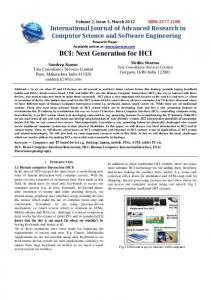
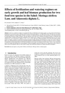
Figure 1. Finished necklace (one variation) in Rhinoceros enviorment (Source: Authors’ research)
The CAD model used in the configuration model is a piece of jewelry, a necklace created in Grasshopper, using Rhinoceros for the graphical interface (fig.1). Grasshopper is a visual programming editor developed by David Rutten at Robert
South East European Journal of Architecture and Design
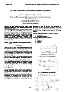
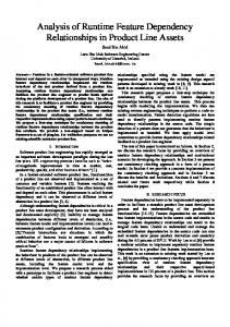
McNeel & Associates. As a plug-in for Rhino3D, Grasshopper is integrated with the robust and versatile modeling environment used by creative professionals across a diverse range of fields, including architecture, engineering, product design, and more. In tandem, Grasshopper and Rhino offer the opportunity to define precise parametric control over models, the capability to explore generative design workflows, and a platform to develop higher-level programming logic – all within an intuitive, graphical interface (Kabazi, 2012a). Although Grasshopper requires substantial effort in building the model definition, non-designers to modify complicated 3D designs (Ghrasshopper, n.d) can easily operate the finished parametrized model. The necklace consists of four main long lines and four shorter ones that are placed in the middle (fig.2). Shorter lines are the one that can be modified by the user, as explained in the addition as for the long lines; they are with fixed dimension and position.
Figure 2. Sceleton of the necklace (Source: Authors’ research)
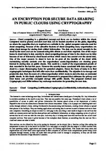
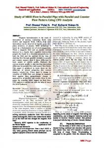
Every one of the lines, which are curves, is created by the Interpolate component, through few points created previously. Figure 3 shows creation of one of the short lines. The points are created directly in the Grasshopper, defined by the threecoordinated axis (X, Y and Z), in that way allowing their additional translation by the user. Translation of the points (3,5,7,9) along the X and Y axis is obtained by sliders, allowing the user easy manipulation as has been shown in previous studies (Ariadi et al., 2012). There is no possibility to move the point along the z-axis for practical reasons.
South East European Journal of Architecture and Design
The long lines are created in the same manner with one exception; they do not have the possibility of changing the position of the lines. 1 2 3 4 5 6 7 8 9 10 11 Figure 3. Movement of one control points along x and y-axis (Source: Authors’ research)
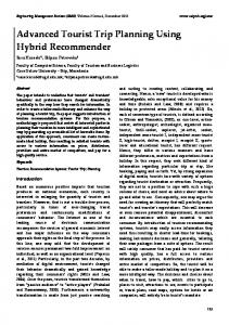
The solid body is constructed with the command sweep, having the line as a guideline and the closed curves as profiles. Closed curves are polygons, with the possibility for the user to choose the number of sides (segments) and the radius (fig. 4). As in the previous example, the users can make the changes of the radius and the segments by sliders. Polygons at the beginning and the end of the line are fixed since they have to be joined with the long lines.
South East European Journal of Architecture and Design
Figure 4. Polygon position on the line (curve) (Source: Authors’ research)
The minimal possible radius is carefully determined so that the FDM machine can afterwards produce the CAD model (fig. 5). The range of the segments is chosen freely, having in mind the minimum number not to be very small since it may result in bad finishing once produced by FDM machine.
Figure 5. Polygon modification in one control point (Source: Authors’ research)
IV. RESULT The outcome of the study is a product configuration model, which assists in the process of creation personalized parts. In this case, part used in the model happens to be jewelry, but it could be any object from keychain to luxurious souvenirs. The code behind the model (fig. 1) is completely created parametrically in Grasshopper (fig.6), which provides changing and improvement if needed.
South East European Journal of Architecture and Design
Figure 6. The code/script for the model (Source: Authors’ research)
The interface of the PCM visible to the user (fig. 7) model consists of four control points in each of the short lines, which makes it sixteen in the whole with adaptable position along x and y-axis. The range of the transition of the control points along the axis is carefully determined, so it will not interfere with any of the fixed points. On each of the lines, there are three polygons, which can be modified by the user. In addition, the range between the smallest and the largest polygon was defined in a way that it can be produced with FDM technology.
Figure 7. User interface of the product configuration model (Source: Authors’ research)
South East European Journal of Architecture and Design
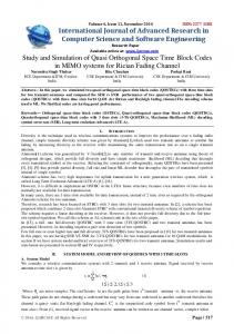
V. DISCUSSION The created PCM is easy to use, with user-friendly interface. All the commands are with standard names, so there will be no confusions for the users. Furthermore, the possibility of having 3D part that interactively changes as the user changes the input is another advantage. The possibilities of change and modification by the user are endless (fig. 8). The user can create unique jewelry which than can be produced without any restriction. Since all the restrictions by the technology are predefined in the model, there is no room for error by the user. Using the sliders for all the modifications makes the model easy to use by people with no software background. A group of industrial design students at the Faculty of Mechanical Engineering evaluated the PCM. According to them, the model is easy to use, intuitive and fun. Having the Rhinoceros graphical interface allows to follow your work in the modification process.
a)
b)
c) Figure 8 (a-c). Result due to radius change of the polygon (Source: Authors’ research)
VI. CONCLUSION The additive technologies are the perfect technologies for creating personalized objects. They are flexible, fast and relatively cheap. With these technologies, designers can use their imagination at its full potential. As these machines are more affordable, anyone can have one and make their own parts. Product configurators are efficient way for companies to leave customers to ‘design’ their products, but still to have some control over it. In fact, it is up to the designer to set the boundaries in which the user can ‘design’. The designer is the one that has to say which element can be modified and in what range, having in mind the characteristics of the technology. For the presented model, next step is conducting an evaluation of the model with the appropriate sample. So far a group of industrial designers that are acquainted with the 3D modeling software product evaluates the PCM evaluates the model. However, since main target group are non-designers and designers with no
South East European Journal of Architecture and Design
knowledge in CAD software the evaluation should be conducted among broader audience. The CAD model that is subject of designing in the presented PCM is designed for specific FDM machine, Stratasys Dimension Elite 1500. In the revised version of the PCM, possibility of choosing machine and material should be proposed. In that manner the ranges of the polygon size will vary. For the further research, web application of the PCM with a wider range of possibilities should be created so the model could be widespread through the internet.
References Adidas, C., n.d. Adidas. [Online] Available at: www.adidas.com/us/customize [Accessed 28 September 2014]. Ariadi, Y., Campbell, R.I., Evans, M.A., Graham I.J. 2012. Combining Additive Manufacturing with Computer Aided Consumer Design. Proceedings of the 23rd International Solid Freeform Fabrication Symposium. Austin, Texas, US. pp. 238-249. Blom, J., 2000. Personalization: A Taxonomy. CHI’00 Extended Abstracts on Human factors in Computing Systems. ACM, New York Dell, C., n.d. Dell. [Online] Available at: www.dell.com/us/business/p/precision-laptop-deals [Accessed 28 September 2014]. Gardiner, J., 2011. Exploring the emerging design territory of construction 3D printing-project led architectural research. (Doctoral dissertation, School of Architecture and Design, RMIT University) Available at: http://researchbank.rmit.edu.au/view/rmit:160277/Gardiner.pdf Gebhardt, A., 2012. Understanding Additive Manufacturing – Rapid prototyping – Rapid Tooling – Rapid Manufacturing. Carl Hanser, München. Grasshopper: Generative modeling for Rhino. [Online] Available at: http://www.grasshopper3d.com/. [Accessed 10 November 2011]. Hague, R., Mansour, S. and Saleh, N., 2004. Material and design considerations for rapid manufacturing. International Journal of Production Research, 42(22), pp.4691-4708. Jensen, R. 1999. The Dream Society: Hot the coming shift from information to imagination will transform your business. New York: McGraw-Hill. Kabazi, Z. 2012a. Foundations, The Grashopper primer third edition. [Online] Available at: http://modelab.is/grasshopper-primer/ [Accessed 28 September 2014]. Kabazi, Z. 20126. Generative Algorithms. [Online] Available at: www.morphogenesism.com [Accessed January 2014]. Kabazi Z. 2012c. Generative Algorithms Concepts and Experiments: Weaving. [Online] Available at: www.morphogenesism.com [Accessed January 2014]. Kruth, J.P., Leu, M.C. and Nakagawa, T., 1998. Progress in additive manufacturing and rapid prototyping. CIRP Annals-Manufacturing Technology, 47(2), pp.525-540. Levy, G.N., Schindel, R. and Kruth, J.P., 2003. Rapid manufacturing and rapid tooling with layer manufacturing (LM) technologies, state of the art and future perspectives. CIRP AnnalsManufacturing Technology, 52(2), pp.589-609. Mugge, R., Schoormans, J.P. and Schifferstein, H.N., 2009. Emotional bonding with personalised products. Journal of Engineering Design, 20(5), pp.467-476. Nike, C., n.d. Nike. [Online] Available at: www.nike.com/us/en_us/c/nikeid [Accessed 28 September 2014]. Stucker, B.R.E.N.T., 2012. Additive manufacturing technologies: technology introduction and business implications. In Frontiers of Engineering: Reports on Leading-Edge Engineering from the 2011 Symposium, National Academies Press, Washington, DC, Sept (pp. 19-21). Vayre, B., Vignat, F. and Villeneuve, F., 2012. Metallic additive manufacturing: state-of-the-art review and prospects. Mechanics & Industry,13(02), pp.89-96. Vink, N.Y., 2003. Customization Choices: Consumer Product Decisions in Mass Customization Environments (Doctoral dissertation, TU Delft, Delft University of Technology).